Force-sensing resistors open up lots of new applications for electronics.
by T.L. PETRUZZELLIS
ONE OF THE MANY modern sensor technologies is really keeping engineers and hobbyists quite busy designing circuits. Billed as the ultimate switch technology, the Force Sensing Resistor (FSR) is a tactile sensor that discerns variations in applied force. The harder you press this thick-film device, the more its resistance decreases.
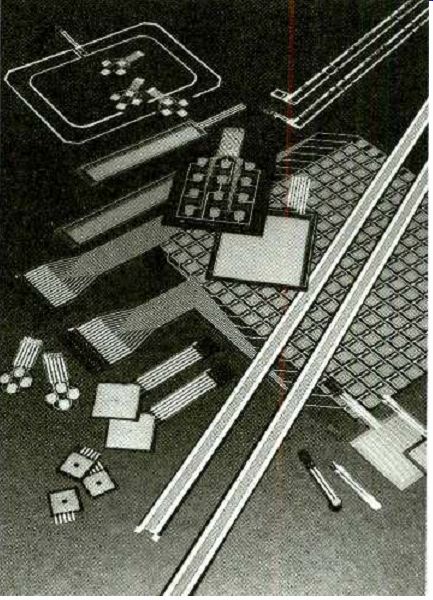
The FSR was first developed for musicians who wanted their electronic pianos to play louder when the keys were pressed harder. FSR's are temperature, chemical, and moisture resistant, and they are insensitive to vibration and electromagnetic interference. FSR's contain no moving parts to wear out, and can withstand over ten million operations. Figure 1 shows some of the different types of FSR's.
FSR's are as thin as business cards, and can be designed to sense forces as light as a fingertip or as heavy as a truck. They can also sense variations in applied pressure and alter their response accordingly. In addition, the sensor's actuation threshold can be adjusted using simple electronics. Applications for FSR's are virtually unlimited, as you can see from Table 1. The FSR is ideally suited to keypads, computer input devices, touch switches, alarm sensors, limit switches, electronic keyboards, digitizers, and pressure sensors.
An FSR device typically exhibits three decades of dynamic resistance change with respect to force and it can operate at much lower currents than most other sensors. The FSR can also be used to construct a linear potentiometer which can monitor the position of a force as well as the amount of applied force. A three-layer XYZ-type FSR device can be constructed that will give an X-Y coordinate position indication with a 0.005-inch resolution, as well as provide the force (Z) measurement. The XYZ pad is ideal for such applications as a graphic pad, pen stylus tablet, or mouse-type device for computer input.
The FSR sensors can also be configured into many different types of switch arrays, with sizes up to 22 x 32 inches, at much lower cost than many other force sensors.
In the past, there were two principle types of force sensors: piezo-polymers and ceramic strain gauges. The fast rise times and high sensitivities of the piezo-polymers cause a lot of unwanted acoustic and vibration pickup. Piezo-polymer sensors often require more complex interfacing than the FSR devices. FSR sensors are not as accurate for precise absolute measurement, but they are much more rugged and cost considerably less than strain-gauge sensors.
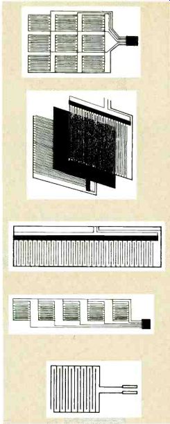

FIG. 1--FORCE-SENSING RESISTORS contain no moving parts to wear out and
then can withstand over ten million operations.
The construction of an FSR is a sandwich of two polymer films or sheets. A conductive pattern is deposited on one of the polymer sheets as a pattern of inter-digiting electrodes as shown in Fig. 2. The electrode pattern often looks like a comb, with the teeth and spacing typically being less than one millimeter.
Next, a proprietary polymer is deposited on the other sheet.
The sheets are then faced together so that the conducting fingers are shunted by the polymer.
The output resistance of the FSR is typically around one megohm with no external force applied. A force versus-resistance graph is shown in Fig. 3.
The graph displays the log/log characteristics of an FSR where the resistance varies from one megohm to around 50 kilohms, depending on the applied force in grams (g). (We know that a gram isn't really a force, but let's just think of it that way for the moment.) Figure 4 shows a force-versus-conductance graph in which a simple linear response is shown from a force of zero grams. A key element in the design of an FSR is the fineness of the pitch of the conducting fingers. The force-versus-resistance relationship is strongly affected by sensor and actuator size, shape, and materials.
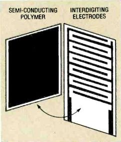
FIG. 2--AN FSR IS MADE OF two polymer films or sheets. A conductive
pattern is deposited on one of the polymer sheets, and a proprietary polymer
is deposited on the other sheet.
Linear potentiometer FSR's
When force-sensing resistors are used to make a linear potentiometer (an FSR-LP), the device can be used to sense both position and applied force. Figure 5 depicts the layered construction of an FSR-LP When wiring an FSR-LP, a voltage is applied between the hot lead and ground. When a force is applied to the force-sensing layer, the wiper contacts are shunted through that layer to one of the conducting fingers of the resistance strip. The voltage from the wiper is then proportional to the distance along the strip.
To sense a force, a resistance measurement is made between the wiper terminal and either the hot or ground lead. Two alternative FSR-LP connection diagrams are shown in Fig. 6.
Force and position measurements are not entirely independent; however, the position measurement can be made unambiguously if the measuring device draws a negligible amount of current (less than 1 microampere) so that there is no voltage drop across the wiper resistance. Therefore, an LF411 or similar opamp-with a low Vos and IBIAS is recommended when interfacing to an FSR-LP Because the contact between the wiper and the resistor is momentary, some kind of sample-and-hold device must be used to interface an FSR; quite often a capacitor between the wiper contact and ground is sufficient to accomplish this.
-------------
TABLE 1-FSR APPLICATIONS Graphic pads Cursor keys Mouse devices Pen stylus tablets Pressure sensors Piano keyboards Toner-level sensors Foot pedals Gait-analysis sensors Artificial-limb force sensors Dental-byte sensors IV drip pressure sensor Bed weight distribution sensor Security tiles /alarm sensors Load cells Suspension sensors Accelerometers Water-level sensors Panel switches Digital tuning controls
Joysticks Game controllers Steering wheels Gas pedals Robotic touch sensors Industrial keyboards
Deadman safety switches
Smart brake pedals
Oil pressure sensors
Limit switches
--------------
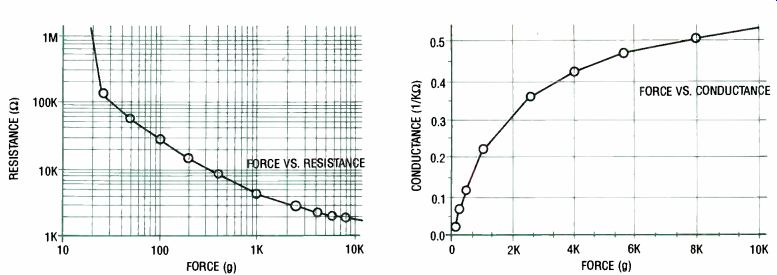
FIG. 3--FORCEVERSUS-RESISTANCE. The resistance varies from one megohm to
around 50 kilohms, depending on the applied force.
FIG. 4--FORCE-VERSUS-CONDUCTANCE. The linear response is shown from a force of zero grams to 10,000 grams, or 10 kilograms.
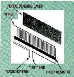
FIG. 5- FSR-LP'S CAN SENSE both position and applied force. This is the
layered construction of an FSR-LP.
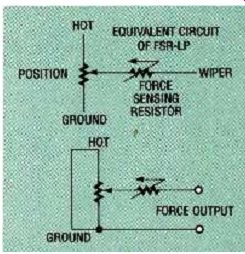
FIG. 6--ALTERNATIVE FSR-LP connection diagrams.
Force measurements are less ambiguous, and very good approximate measurements can be obtained by shorting the two fixed resistor ends (hot and ground) together, and measuring the resistance between the combined leads and the wiper. If the force is applied at the middle of the potentiometer, the device will have an additional resistance of one half of the total fixed resistance, because the resulting middle contact parallels the two halves of the fixed resistor. If, on the other hand, force is applied to either end of the FSR-LP's active area, the fixed resistance is essentially shorted out. That problem can be overcome by making the FSR resistance high compared to the potentiometer resistance, therefore making a low current position measurement a must.
The slight force-measurement error can also be subtracted out with a simple analog circuit or, given a position measurement, compensated for in software if a microprocessor is used with the system.
The positional resolution of a force and position sensing resistor (FPSR) depends on the width of the applied force, distribution, and the fineness of the conductive fingers, which is typically in the 10-100 micrometer range.
FSR-LP XYZ
An XYZ pad or tablet is constructed by placing two FSR-LP's back-to-back and perpendicular to each other. An XYZ pad can measure the position of a force on an X-Y coordinate plane, as well as the applied force (Z). Figure 7 shows the layered construction of an XYZ pad. Note that an unambiguous position can be measured only for a single applied force; multiple force contacts will cause false readings. That is not a problem for graphics pads, mouse devices, or pen stylus tablets, but the XYZ pad cannot be used for complex pattern recognition. Position accuracy of an XYZ pad based on FSR-LP's is typically about 1 percent.
A true force sensor will give a constant reading at a constant force, independent of the area over which the force is applied, or its distribution. If a constant force is applied to a true pressure sensor, the reading will be inversely proportional to the area of the applied force. An FSR has a function that is between a force and pressure sensor. A typical FSR will display the resistance of the square root of the area of the applied force.
That holds true when the force footprint is smaller than the FSR's active area, and large compared to the spacing between the conductive electrodes or fingers. Because of the sensitivity of the FSR's resistance to the area and distribution of force, the force footprint must be held constant in position and distribution. An elastomeric or rubber overlay placed over the sensor can solve that problem. The FSR can be used as a pressure sensor when the applied force is large compared to the FSR's active area.
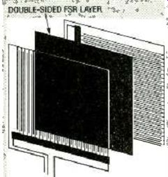
FIG. 7--AN XYZ PAD IS TWO FSR-LP's back-to-back and perpendicular to each
other.
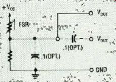
FIG. 8--FSR ANALOG INTERFACE. Increased pressure results in increased voltage
output.
FSR devices are designed to be easily interfaced with a wide variety of circuitry. A simple analog interface is shown in Fig. 8. A basic requirement for interfacing an FSR is to ensure that the current through the device does not exceed 1 mA/cm^2 of the activation footprint. The voltage measurement across the FSR is then related to the applied force, and increased pressure results in increased voltage output. Precision measurements, however, are a somewhat more difficult because of the shape of the power law curve. For higher precision measurements, it is usually wise to go into the digital domain as soon as possible, so that the log/log characteristics of the device can be translated into more linear results.
If your design calls for measurement of impact (i.e. a data keyboard), then the FSR can be placed in a voltage divider, and the divider can be capacitively coupled to the succeeding stages. That would eliminate offset problems due to a preload condition. The interface shown in Fig. 9 is useful where a higher current or a lower source impedance is necessary. The opamp can be used either as a unity-gain buffer, or it can be configured to amplify the FSR's output. Offsets can be trimmed by the 500-ohm potentiometer.
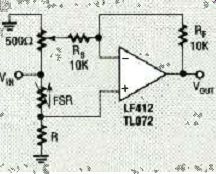
FIG. 9-THIS INTERFACE is useful when higher current or lower source impedance
is necessary.
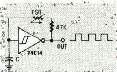
FIG. 10--FORCE –TO-FREQUENCY CONVERTER. An oscillator is constructed with
the FSR as a feedback element around a Schmitt trigger.
Gain is set by the ratio of the resistors RF and Rs. Suggested op-amps for that circuit are the LF351/353 or the TL071/72 series of low bias-current devices.
The low bias currents of those op-amps reduces the possible input offsets, due to the high source impedances of the FSR. Figure 10 shows a force-to-frequency converter. In that circuit, an oscillator is constructed with the FSR as a feedback element around a Schmitt trigger integrated circuit. At zero pressure, the FSR is an open circuit. Depending on the last stage of trigger, the output remains constant-either high or low. When pressure is applied to the FSR, the oscillator starts, and its frequency increases with increasing force applied to the FSR. Resistor R1 limits the current through the sensor. Bypassing R1 with a capacitor will cause the curve to be steeper at higher forces. Connecting a large-value resistor in parallel with the capacitor (C), quenches any tendency for the circuit to oscillate at low applied forces. When using the circuit with CMOS or TTL, a digital process can be controlled by counting leading or trailing edges of the oscillator output.
Industry standard connectors, such as pin or compression types, can interface the FSR devices. Conductive adhesives are also commonly used to attach leads to FSR devices.
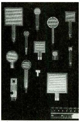
FIG.11--THIS PHOTOGRAPH shows some of the many different shapes and sizes
of available force-sensitive resistors. The ruler in the lower right-hand
corner gives you an idea of their size.
Do not attempt to solder wire leads directly to the polymer sensor, because direct heat will destroy the device.
The force-sensing resistors require a backing for activation accuracy, as mentioned previously. The most unpredictable aspect of the FSR's force /resistance characteristic is the pressure range under 100 grams/ cm^2. If you are going to measure small forces with your FSR, you can preload the FSR with a 100-200 gram /cm^2 load and measure the resistance changes. Elastomer or plastic overlays can be used to enhance the FSR's response characteristics by evenly spreading the actuator's force.
FSR sensors are available in many sizes, configurations, and shapes, and custom devices can be designed by the manufacturer. For more information on FSR technology, write on your company letterhead to Interlink Electronics, 1110 Mark Ave., Carpinteria, CA 93013. An evaluation /prototype kit is also available for $79.95.
------------------
Also see: Link | --Link | --Resistors