Build a professional-quality ultrasonic cleaner and keep hard-to-clean connectors, parts, and tools spic and span.
by REINHARD METZ
ULTRASONIC CLEANING HAS BEEN commonplace in commerce and industry for years, particularly for cleaning small, convoluted parts that would be a difficult or impossible to clean otherwise. Items that are routinely cleaned ultrasonically include machine parts, standard and microminiature tools and connectors.
Factory-made ultrasonic cleaners are still too expensive for the average consumer and hobbyist. But with the drawings, photos, and text in this article, you can build your own ultrasonic cleaner. You have options in building this ultrasonic cleaner. You can build the complete system with microprocessor-based time and temperature controls, or you can build only the basic model with on-off controls. You'll be surprised at the low-cost of the parts, regardless of the option you choose. The basic specifications for the ultrasonic cleaner are given in Table 1.
Only non-toxic, nonflammable solutions will be needed to do effective cleaning with this ultrasonic cleaner. You'll be able to clean many different kinds of household or shop objects that are hard to clean--or, in the past, have just been too much trouble to clean well with conventional methods. Those objects include jewelry, kitchen utensils, circuit boards, bicycle and auto parts, and tools. What is more, you can do all your ultrasonic cleaning indoors-you don't have to go into your garage or backyard to keep noxious fumes out of your house.
----------------

TABLE 1 -- LEADING SPECIFICATIONS
FOR THE ULTRASONIC CLEANER
Transducers piezoelectric
Operating frequency 40 to 60 kHz
Cleaning pan capacity 3/4 gallon
Microcontroller Intel 8751
Timing range* 1 to 99 min.
Solution temperature w/heater* 25 to 99 °C
Power requirement 117-V AC, 60 Hz
*Optional feature
--------------------
Ultrasonic cleaning
The basis for ultrasonic cleaning is a bubbling action in a fluid called cavitation-millions of tiny bubbles forming and collapsing within the cleaning solution do the scouring.
You have probably seen the cartoons of thousands of cleaning bubbles at work on the TV commercials for bathroom cleaners.
The big difference here is that with our cleaner, the bubbles are created ultrasonically by piezoelectric transducers, not by the solution itself.
The disk-shaped piezoelectric transducers are bonded to the underside of the cleaning pan.
The dimensions of these barium-titanate ceramic disks change continuously in response to high-frequency signals applied across their sensitive surfaces. These transducers are similar to those used in marine depth finders.
The compression and expansion of the crystalline transducers is coupled mechanically through the bottom of the pan to create the cavitation bubbles in any cleaning solution that you use. (For a complete description of the piezoelectric effect, refer to the January 1993 Electronics Now). If the cleaning solution that you select is a recognized solvent for the contaminants that you expect to find on the parts to be cleaned (for example, oil or grease), the ultrasonic cleaner will enhance the cleaning action of that solution.
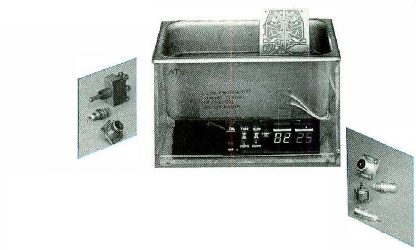
Description of the cleaner.
The ultrasonic cleaner has three main parts: a stainless steel pan with two transducers attached, a large circuit board containing the power oscillator and time- and temperature-control circuitry, and a small switch /display circuit board containing the control switches and LED displays.
The large circuit board (approximately 5 x 8 inches) is shown in Fig. 1. The left side of the board is occupied by the power transistor amplifier for the oscillator and its heat sink.
The oscillator, made up of components on the board, supplies a 40to 60-kHz, 1000-volt sinewave to the piezoelectric transducers. The large objects in the center of the board are the two transformers-one standard and one special. The microcontroller and other IC's are located on the right side of the board.
All of the switches are located on the smaller (approximately 2 x 5-inch) PC board shown in Fig. 2. They include, from the left, the ON-OFF power switch, the TIME UP-DOWN toggle switch, the TEMP UP-DOWN SWITCH and the START pushbutton. The green two-digit, seven-segment display on the left indicates time, and red one to its right indicates temperature.
Figure 3 shows the stainless steel cleaner pan upside down with the two piezoelectric ceramic transducers (white disks) bonded to a stainless steel plate which, in turn, is bonded to the pan bottom. The plate transmits the vibrations from the transducers more uniformly through the bottom of the pan to the cleaning solution, and it helps to protect the brittle transducers from damage that might be caused by objects accidentally dropped into the pan.
The ultrasonic cleaner will work very well without the time and temperature circuitry, but building them should be interesting, and they will add value to the cleaner. The controls will be especially useful if you plan to heat the cleaning fluid, and want to set time limits for the cleaning action on specific objects. Moreover, the controls will shut the unit off automatically.
Both time and temperature are programmable-time from 1 to 99 minutes, and temperature from 25° to 99° C. The time and temperature functions are controlled by an Intel 8-bit CMOS 8751 microcontroller, which you can program or purchase already programmed.
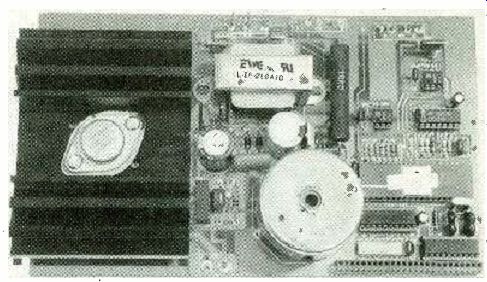
Fig. 1--CIRCUIT BOARD CONTAINING power oscillator and microcontroller-based
time and temperature control circuitry.
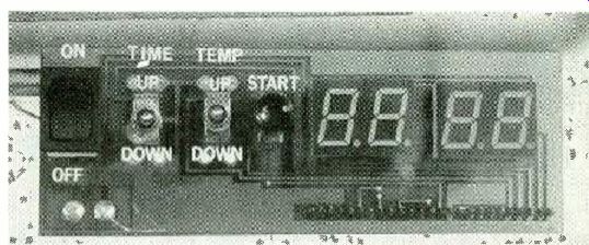
FIG. 2--CIRCUIT BOARD CONTAINING the manual operating control switches
and LED time and temperature digital displays
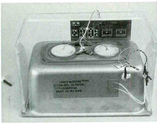
FIG. 3--VIEW OF INVERTED CLEANER PAN with two piezoelectric transducers
mounted on it. The back of the control /display board is shown in the
background.
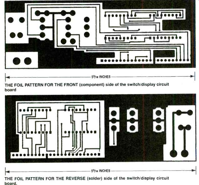
----------- THE FOIL PATTERN FOR THE FRONT (component) side of the
switch display circuit board
THE FOIL PATTERN FOR THE REVERSE (solder) side of the switch display circuit board.
Driver circuit
Refer to the right side of the two-page schematic diagram Fig. 4. The amplifier in the transducer oscillator driver is a Hitachi 2SC1922 bipolar power transistor, Q1. The oscillator tank circuit is formed by the inductance the secondary winding of transformer T1 and the effective capacitance of transducers RES1 and RES2. Bridge rectifier BR1 and capacitor C1 form a 160-volt DC power supply operated from the 120-volt, 60Hz line. Resistor R1 provides the base bias for Q1, through the feedback winding of T1.
As Q1 turns on, current flows through the primary of Ti, which generates an opposing voltage in its feedback winding, tending to turn Q1 off again. At the parallel-resonant frequency of the tank circuit, made up of the secondary of Ti, RES1 and RES2, the phase shift between the base and collector of Q1 is exactly 180 °, which is necessary for circuit oscillation. The winding ratios of Ti determine the output voltage, and thus the voltage applied to the two transducers.
The input supply voltage is 160 volts DC, and the turns ratio is about 5 to 1, so the output voltage is about 1000 volts peak-to-peak. In addition, the DC startup current provided by R1 and C2 is the AC drive current for Q1. Resistor R2 and capacitor C3 suppress spurious oscillations at frequencies other than the tank's primary resonant frequency.
As the drive voltage across the transducers swings through the 1000-volt peaks, the transducers expand and contract across their thickness dimensions, and their vibrations are coupled through the pan walls to the cleaning solution.
Time and temperature control The CMOS8751 microcontroller, IC1, is the key component of both time and temperature controls. It responds to input from the START button, TIME UP-DOWN Switch, TEMP UP -DOWN switch, and the temperature-sensor circuit. It provides the drive signals for the two-digit time and two-digit temperature LED displays, the transducer power Triac Q2, and the heater Iliac Q3.
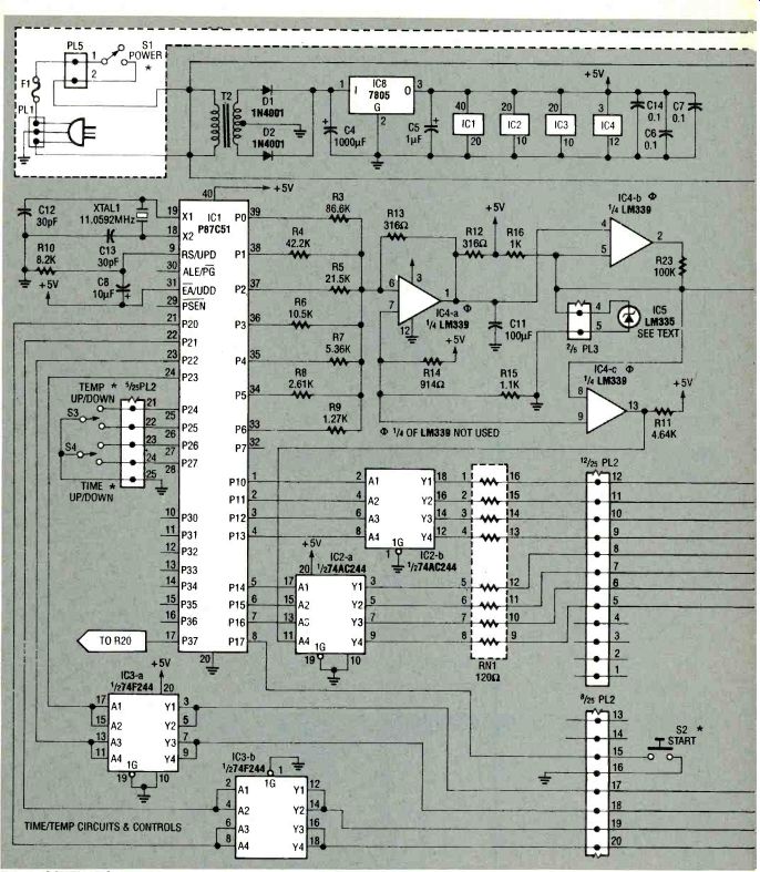
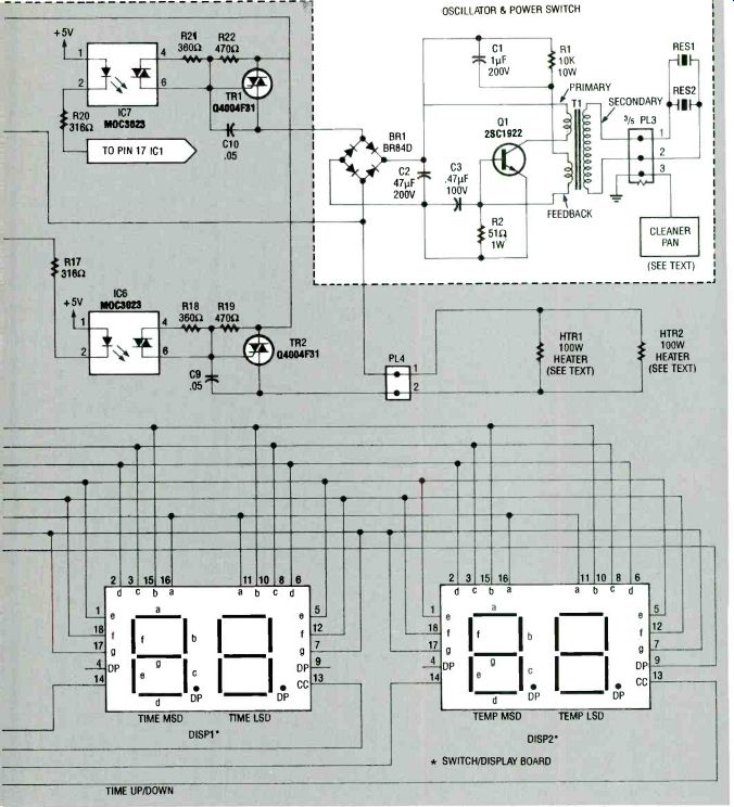
FIG. 4--SCHEMATIC FOR THE ULTRASONC CLEANER is divided by dotted lines
into the operating control section and the time-temperature control
section
An assembly-code listing for the Intel 8751 firmware is available from the address given in the Parts List or from the R-E BBS (516293-3000; 1200/ 2400 baud 8, N, I). The program consists of a loop whose time corresponds to the multiplex rate of the LED displays. Each time the loop is traversed, one of the four digits is enabled; the loop rate is sufficient to eliminate display flicker.
Within the loop, inputs are checked and various time, temperature, and display variables are updated. The switches provide direct input through the I/O port.
Temperature is registered in binary format, and it is converted from a digital to an analog signal by resistor string R3 through R9 and IC4-a. This analog signal is then compared with the pan temperature signal from IC5 by IC4-b. When solution temperature falls below the selected threshold, IC6 turns on to energize Q3, which provides current to pan heaters HTR1 and HTR2. When the cleaner is first turned on, the temperature is automatically reset to 25 degrees C. Whenever heat is on, the decimal point of the temperature display LED is turned on.
The timer circuit or function depends on the internal timing capabilities of the '8751, IC1. When the START button is pressed, Q2 is energized, powering the transducers. The internally registered time is decremented and displayed, and when zero time is reached, Q2 is turned off and the original time is reset. When the cleaner is turned on, the time is set automatically to 5 minutes, but this setting can be adjusted up or down.
Finally, multiplexed segment and digit drive is provided to the displays by IC2, IC3, and current is limited by the eight 120ohm resistors in network RN1.
Power for the control section is provided by T2, D1, D2, and 5volt regulator IC8. Further details of the firmware operation can be found by reading the code comments.
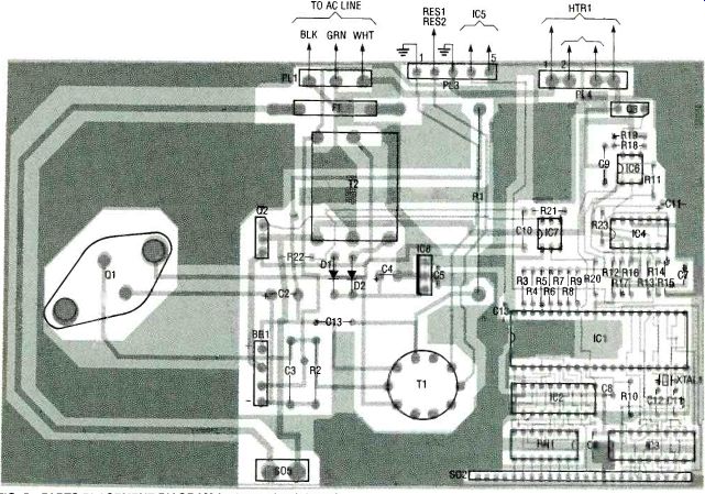
FIG. 5--PARTS PLACEMENT DIAGRAM for large circuit board.
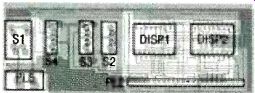
FIG.6-PARTS PLACEMENT DIAGRAM for switch /display circuit board.
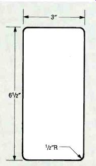
FIG. 7--OUTLINE FOR THE TRANSDUCER MOUNTING PLATE to be cut from 0.063-inch
stainless steel plate.
Circuit board assembly
Refer to Fig. 4, the two-page schematic for the complete ultrasonic cleaner. A boundary on the schematic separates the oscillator and power switch circuit from the time and temperature circuits and controls. This permits you to distinguish between the basic circuitry needed to operate the cleaner and the time and temperature control circuitry.
Note that both circuit boards are two-sided. Foils for the parts placement and solder sides of both boards are included here.
Making these boards might prove to be a challenge if you have not had much experience fabricating printed circuit boards of this complexity.
Therefore, both boards complete with solder masks and through-hole plating are offered in the Parts List. Refer to Fig. 5, the parts placement diagram for the large board circuit board. The order of component placement on this circuit board is not critical whether or not you plan to include the time /temperature circuitry and control switches.
The only component on that board not available as a standard catalog item is transformer T1. You can purchase transformer T1 from the same source given in the Parts List or you can wind your own if you choose to do so.
If you choose to wind your own transformer T1, it will be necessary for you to obtain a ferrite core and Litz wire. The core in the prototype is a Ferrox cube 4229-PA275 ferrite core obtainable from Philips Components Discrete Products, Saugerties, NY 12477. The primary winding has 20 turns of 21 strand/36 AWG Litz wire arid the secondary has 99 turns of the same wire. Feedback is obtained with 3 1/2 turns of No. 22 AWG wire.
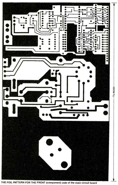
-----------THE FOIL PATTERN FOR THE FRONT (component) side of the main circuit board
Be sure to double check the values of all the components as you insert them. Power transistor Q1 is positioned on top of the heatsink as shown in Fig. 1, and both parts are fastened to the board with screws at the same time. Insulate Q1 from the heatsink with a mica insulator coated liberally with heatsink grease. After mounting Q1, check its isolation with a meter to be sure that it really is insulated from the other components or conductors.
Mount transformer T1 by the lugs on its frame and connect its wires individually as indicated in Fig. 4. If you plan to build the cleaner without the time and temperature controls, the positions for those components will remain open. The precision temperature sensor, LM355, (IC5) will be epoxied on the bottom of the stainless steel pan, and be connected to the board by a twisted pair of wires at P3.
Sockets are recommended for all DIP-style IC's (IC1, IC2, IC3, IC4, IC6, IC7), particularly the microcontroller, IC1. Insert all resistors, capacitors, plugs (three-pin plug, PL1; five-pin plug, PL3; and four-pin plug, PIA), sockets (25-pin socket SO2 and two-pin socket S05, resistor network, rectifier bridge, Triacs and diodes. Solder all leads and trim excess lead lengths.
Examine the circuit board closely to be sure there are no accidental solder bridges or cold joints.
Refer to the parts positioning diagram, Fig. 6, and insert the three switches (S1-S3), the sockets for the two dual-digit, segmented LED displays, DISP1 and DISP2, and the right-angle, 25-pin header PL2. Solder all leads and trim excess. Again, check for inadvertent solder bridges or cold solder joints before inserting the displays.
Transducer plate and tank Start the assembly of the tank and transducers by cutting out a +3 x 6 1/2-inch rectangle from 0.062-inch stainless steel plate as shown in Fig. 7. Round the corners to '/2inch radiuses, deburr all edges, and sand or grind both sides so the plate will lie flush against the bottom of the stainless steel tray.
Next, prepare both transducers, RES1 and RES2, for wire attachment by cleaning their surfaces with alcohol or other suitable solvent. Strip about ¼-inch of insulation from both ends of a pair of 24 to 26 AWG multistrand hookup wires approximately 12 inches long for transducer connection. Flatten the wires by fanning out their stranded ends, and tin the strands with lead-tin solder.
Carefully solder the fanned out strands of one wire to the centers of each transducer as rapidly as possible to prevent overheating and damaging the ceramic transducer. Then solder a copper wire, approximately 3 inches long to connect the reverse sides of the transducers, observing the same precautions about soldering.
Note: the transducers are polarized, and both must have the same polarity on top and on the bottom. If this is not observed, the opposing vibrations of each transducer will cancel the effect of the other one.
After the wires are soldered to the transducers, the next step is to bond the transducers to the rectangular transducer mounting plate. Refer to Figs. 3 and 8 to see how the transducers are positioned on the plate. Mix the two parts of a high quality, slow-setting epoxy and apply a film of it to the plate. Position the transducers on the plate, and while applying slight pressure, rotate them slightly so that some epoxy underneath the transducers is squeezed out to form a bead of epoxy around the edges of the transducers where they contact the plate.
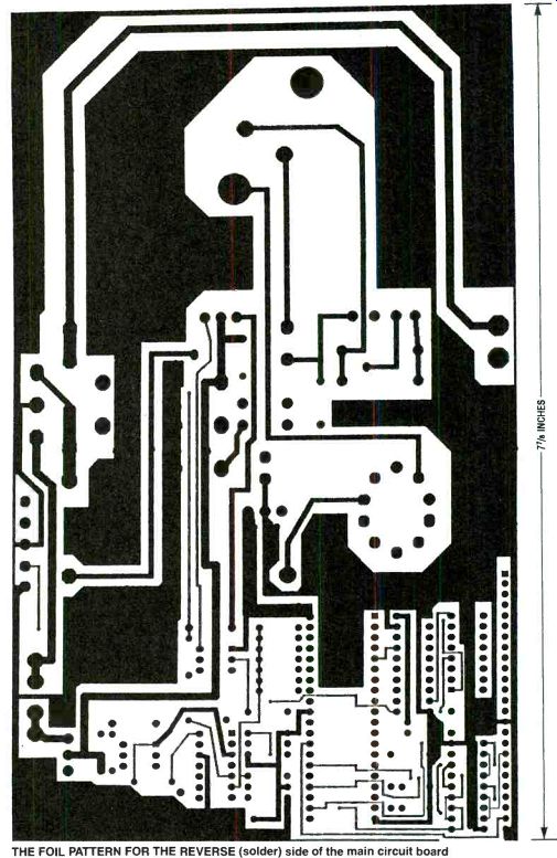
--------THE FOIL PATTERN FOR THE REVERSE (solder) side of the main circuit board
When the epoxy holding the transducers has set, apply epoxy to the transducer plate assembly and cement it to the bottom of the tank, also as shown in Figs. 3 and 8. If you intend to include the optional temperature control, adhere the two heating elements, HTR1 and HTR2, to the sides of the pan (one is shown in Fig. 3.) Solder or crimp sleeves to the ends of the heater wires. Solder a twisted pair of hook-up wire approximately 12 inches long to the LM335 temperature transducer (IC5) and solder or crimp sleeves to the other ends of the four wires. Epoxy temperature sensor IC5 to the bottom of the pan as shown in Fig. 8. Mark the wires to identify their polarity.
Final wiring and assembly
There are no requirements for the ultrasonic cleaner case. You can make one by assembling a box from 1/4-inch sheet plastic or you can purchase a small 6 x 6 x 9-inch plastic storage bin from your neighborhood hardware or houseware store. The bin will work very well as a protective case.
Pass the bare ends of the three-wire line cord terminated with a three-prong plug through the grommeted hole in the case. Strip the ends of the wires for soldered or crimped sleeves to connect them to three-pronged plug PL1, observing the ground wire. The ON-OFF switch on the switch-display board will perform the switching function when the small board is plugged into the large board through plug PL5.
Install fuse F1 in its holder, and place the large circuit board in the case. Connect the transducer, heater, and temperature transducer wires by pressing their terminating sleeves over the header pins as shown in Fig. 8. Plug the switch/display board into the sockets S02 and S05. Carefully check all component values and placement, and all wiring against the schematic, Fig. 4, before carrying out the test and checkout procedures. Make any corrections necessary.
Before operating the ultrasonic cleaner, check to be sure that the pan is grounded to the line cord ground and the primary of transformer T1 is isolated from its secondary and tank circuit.
----------------
PARTS LIST
All resistors are 1/4-watt, metalized film, 5 % unless otherwise stated.
R110,000 ohms, wirewound, 10 watt R2-51 ohms, wirewound, 1 watt R3-86,600 ohms R442,200 ohms R5 21,500 ohms R6 10,500 ohms
R7-5300 ohms R8-2610 ohms R9-1270 ohms R10-8200 ohms R11-4640 ohms R12, R13-316 ohms R14-914 ohms R15-1100 ohms R16-1000 ohms R17, R20-316 ohms R18, R21-360 ohms R19, R22-470 ohms
Capacitors
C1-1 uF, 200 volt, polyester film C2-47µF, 200 volt, polyester film C30.47µF, 100 volt, polyester film C41000µF, 15 volt, aluminum electrolytic C5-11.1.F,15 volts, aluminum electrolytic C6, C7, C14-.11.LF, polyester film C8-10µF, 15 volts, aluminum electrolytic C9, C10-0.05µF, polyester film C11 100 muF, 15 volt, aluminum electrolytic C12, C13-30 pF
Semiconductors
IC1-87C51 CMOS microcontroller with EPROM, Intel or equiv.
IC2 74AC244PC octal bus driver, non-inverting, National or equiv.
IC3 74F244 octal bus driver, non-inverting, National or equiv.
IC4-LM339 quad comparator, National or equiv.
IC5-LM335 temperature transducer, National or equiv.
IC6, IC7GE3023 optoisolator, Harris or equiv.
IC8LM340TS (7805) voltage regulator, 1A, Motorola or equiv.
Q1 2SC1922 power transistor, Hitachi or equiv.
Q2, Q3 triac, Teccor Q4 004F31 or equiv.
D1, D21N4001 silicon diode DISP1LN526GA 7segment LED display, Panasonic or equiv.
DISP 2LN526RA 7segment LED display, Panasonic or equiv.
BR1BR840, full wave rectifier bridge, Diodes Inc. or equiv.
RN1-eight 120 ohm resistor network, CTS9043 or equiv.
Other components
F1-fuse, 6 ampere, standard HTR1, HTR2-100 watts, 120 volts, Watlow F02005007 or equivalent
S1 switch, rocker, panel-mounted
S2 switch, miniature toggle, momentary SPST, panel-mounted
S3, S4 switch, miniature toggle, momentary SPDT, panel-mounted XTAL111.0592 MHz crystal holder
T1 transformer, custom wound (see text)
T2 transformer, EWC Inc.
EL16260A10 or equiv.
P1 three-pin header
P2-25-pin right-angle header
P3-five-pin header
P4 four-pin header
P5-two-pin header
S02-25-pin socket S02-2-pin socket
RES1, RES2 piezoelectric transducers, ceramic, 2-inch, Vernitron 56786 PZT-4 or equiv.
Miscellaneous: large and small circuit boards, stainless steel tank (6 7/8 x 4 1/4 x 4 inches, Polarware No.E904 or equiv.), Anodized aluminum heat sink, (4 x 3 x 2 inches), transducer mounting plate (see text), mica insulator for a bipolar power transistor, thermal conductive grease, sockets for IC1, IC2, IC3, IC4, IC5, IC6, IC7, three-wire power cord with 3-prong plug, line cord grommet, fuse holder, case (see text), hookup wire, wire sockets, epoxy, solder.
Note: The following parts are available from A &T Labs, P.O. Box 4884, Wheaton, IL 60187: Kit of parts for the ultrasonic cleaner without time and temperature controls / displays or case, $169.00. Kit of all parts for the complete ultrasonic cleaner including programmed 8751 microcontroller except case, $249.00
Double-sided printed circuit boards-large, $25.00; small, $9.00
Programmed Intel 8751 micro-controller, $29.00
Custom-wound transformer T1, $69.00
Ceramic piezoelectric transducers RES1 and RES2, $32.00
Stainless steel cleaner pan, $19.00
Add 6% shipping and handling on all orders paid for by check or money order.
Add 10% shipping and handling on all COD orders ( U.S. only) via UPS. Illinois residents add 6.75% state sales tax. For all correspondence please include a stamped, self-addressed envelope.
------------------
Test and checkout procedure
Temporarily support the tank next to the circuit board. Fill the pan at least half full with water.
Caution--Never operate the cleaner unless the pan is at least half full of liquid. Apply power, and turn on the cleaner.
You should hear a hissing sound from the pan and you should be able to feel the vibrations with your fingertips on the edge of the pan. If you do not hear or feel these operating indications, check for the presence of the primary 160 volts at C1, and +5 volts at C5.
When testing, remember that the primary circuit is connected to the 120-volt power line, so exercise caution to avoid electric shock. Also, the voltage applied to the transducers is about 1000 volts. If the unit fails to function at turn-on, check for the presence of 11 MHz at pin 18 of the microcontroller IC1, and look for changes in the time and temperature display LED's. At turn-on, those digital displays should readout 5 and 25, respectively.
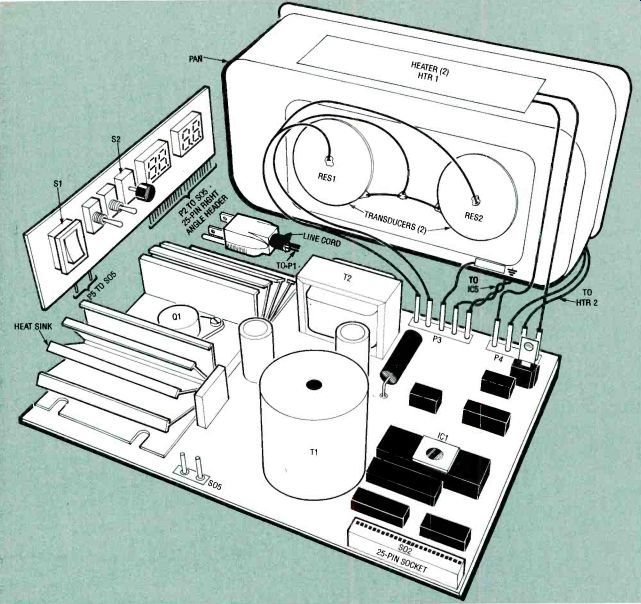
FIG. 8--EXPLODED VIEW showing wiring connections between the main
circuit board to the piezoelectric transducers, pan heaters, and temperature
sensors mounted on the pan.
Although the design frequency should be close to optimal, further adjustment could improve efficiency. Perform any additional tuning by turning the slug core of transformer T1. Adjust it gradually until you are able to observe maximum turbulence in the cleaning fluid.
One way to determine a maximum is by adding a drop of food coloring to the water, and adjusting for maximum dispersion rate of the color in solution.
Cleaner operation You can purchase cleaning fluids from hardware, auto parts, and grocery stores, but you can also easily mix your own. You might want to experiment with cleaning mixtures. A general rule of thumb is that any cleaning solution that works satisfactorily in cleaning objects by hand methods will also work in the ultrasonic cleaner. Liquid detergent in water, for example, is a good general cleaner, while ammonia in water works well for jewelry.
Carburetor cleaner cleans carburetors and other automotive, bicycle or machine parts that are coated with oily or greasy contaminants.
Before cleaning any object in the ultrasonic cleaner, it is a good idea to remove as much surface dirt and grime as possible manually with paper towels, brushes, or cotton rags to minimize the contamination entering the cleaning solution. The cleaner is most effective in cleaning hard-to-reach recessed areas. Place the parts to be cleaned in the pan filled with the cleaning solution, and turn on the cleaner. Experiment with various objects to determine their optimum cleaning time.
If the cleaning solution is to be heated, turn the main power on first to allow the solution to reach its set temperature. Time and temperature values are set by pushing the up /down buttons.
Precautions
The cleaner operates from 120-volt line power and there are liquids present; together these pose an added electric shock hazard if proper grounding is not maintained. Moreover, some cleaning solutions and their vapors can be toxic.
Other precautions are: The use of flammable cleaning fluids is not recommended.
If they are used, exercise all reasonable precautions by moving the cleaner out of doors and never leave it unattended while the fluid is in the pan. Be sure to return all toxic fluids to a safe storage container when cleaning is complete. Never use gasoline as a cleaning fluid! Never put your hands into the cleaning solution when the cleaner is on. The intense vibrations can drive particulates into your skin, and the ultrasonic energy could damage body tissues.
Minimize any time spent close to the operating cleaner because the high frequency 40kHz oscillations can cause headaches and might lead to hearing impairment although they are not audible.
Be sure that the pan is at least half filled with solution during all cleaning operations.
Place any objects to be cleaned carefully in the pan with tongs, and take care not to drop any heavy object in the pan that could damage the fragile transducers.
The use of chlorofluorocarbon (CFC) solvents, commonly used to remove solder paste from circuit boards, is not recommended because of their threat to the environment.
Also see: TIME DELAY RELAY (DIY Project)