Potcores offer many advantages when you need to use an inductor in a circuit. This article details a simplified design method for two common potcore sizes based on a nomograph.
FERRITE POTCORES are widely used in the construction of small inductors and transformers. However very few amateurs know how to choose a core appropriate to their needs, or how to wind a coil of specific inductance. This article describes a simple method of designing coils for low frequency applications. The design of coils for high frequency applications, and of transformers, is beyond the scope of this article. Design details given apply only to the Philips 'P' series of pot cores and more particularly to the 18 mm (P18/11) and 26 mm (P26/16) diameter cores which are the most commonly available.
Each core size is available in four different ferrite materials (3H1, 3B7, 3D3, 4C6) to cover the frequency range from audio to about 20 MHz. Addition ally each material, in each size, is available with a number of permeabilities to cover different inductance, stability and Q factor requirements. There are two factors commonly used to classify ferrite cores. These are effective permeability ( µe) and AL factor.
The µe factor is primarily determined by the permeability of the material used and its cross sectional area, and secondly by the air gap left between the centers of the two core halves. For example an 18 mm 3B7 core without any air gap (type 0 4000) has a µe of 1750 and a tolerance on inductance of ±25%. The use of increasingly larger air gaps in the same core size and material lowers the ge but increases the stability and reduces the tolerance on inductance.
A second factor in common usage is AL. This factor gives, in nano-henries, the inductance of ONE turn on the core.
The inductance of N turns on the core is
L = N^2 AL x 10^-3 millihenries
The selection of a core size, a core material, a permeability value, a wire size and the number of turns depends on all the following factors:-
- inductance, stability of inductance
- frequency range
- Q factor
- unbalanced dc coil current
- level of ac coil current
Choosing the correct core taking all these factors into account is a difficult task indeed. However a large number of r core types are eliminated by first selecting in accordance with frequency range and stability.
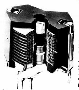
Cutaway view of a potcore showing the winding on the interne bobbin and the inductance adjustor in the centre. The ferrite 'pot' comes in two halves, held together with a clip.
Frequency range
Firstly select the core material from Table 1 in accordance with the desired frequency range. To choose between 3H1 and 3B7 it is necessary to consider temperature stability.
If the tuning capacitors associated with the coil have small or varying temperature coefficients, a 3B7 core should be used as they have the lowest temperature coefficient in the range 0° - 70°C. Alternatively, if using polystyrene capacitors (temp. coeff. - 150 ppm/°C) a 3H1 core having an effective permeability (µe) around 150 will give excellent temperature compensation for the temperature coefficient of these capacitors.
Inductance stability Since the inductance of a coil is TABLE 1 FREQUENCY RANGE
proportional to core permeability, the change of effective permeability (µe)
with temperature determines the stability of inductance.
The percentage change of inductance with temperature is linearly proportional to µe and hence low ete cores should be used for greatest stability.
Stability is therefore obtained at the expense of inductance obtainable with a given core size.
The temperature effect is not large enough to affect any but the most critical of applications and the tolerance on inductance as stated in Tables 2 and 3 will be obtained over the temperature range + 15° to + 35°C.
Direct current
A direct current in the winding will change the inductance value of the core and if large enough, could cause saturation. In general, large air gaps, and hence lower permeability (µe), cores should be used where large dc currents are flowing.
Q factor
The Q of a coil is influenced by different factors at different frequencies.
At frequencies below 10kHz it is almost completely determined by the dc resistance of the winding. The Q factor of any given coil increases linearly with frequency, and the larger the core, the larger the Q. The highest Q factors are obtainable by using gapless cores of 3H1 or 3B7 material (providing that tolerance and stability are acceptable) eg. 04000 series (P18/11) and 08000 series (P26/ 16).
Throughout the ultrasonic range core and winding losses affect Q, but Q factors of several hundred may still be obtained by optimum choice of wire and core, such that core and winding losses are equal. For further information, on optimum design, reference should be made to Philips Data Handbook -- Components and Materials, Vol. 4.
At higher ultrasonic and lower radio frequencies, additional factors of dielectric and skin-effect losses and parallel winding capacitance, all affect Q, making exact design difficult. Use of Litz wires, split section formers and small cores with low µe values will assist.
------------
120 Reprints of this article on quality, heavy grade paper are available from the magazine for $2.50 each post paid. Make out your cheque or money order to ETI/Modern Magazines and send your order to "Designing Potcore Inductors Reprint", Electronics Today International, 15 Boundary St, Rushcutters Bay NSW 2011.
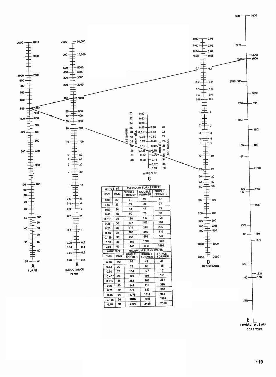
TO USE THIS CHART MAY BE USED TO DESIGN INDUCTORS USING PHILIPS P18/11 OR P26/16 POTCORES FOR P18/11 CORES I18mm OIA) USE THE FIGURES ON THE LEFT OF THE SCALES, AND FOR P26/16 CORES (26mm OIA) USE THE FIGURES ON THE RIGHT. NOTE THAT ON SCALE E ye VALUES ARE GIVEN IN BRACKETS WHEREAS AL FIGURES ARE UNBRACKETED.
FOR EXAMPLE. ASSUME WE REOUIRE A 100mH INDUCTOR ON A P18/11 CORE HAVING AN AL OF 400. LAY A RULER BETWEEN 100mH ON THE LEFT OF SCALE B AND AN AL OF 400 ON THE LEFT OF SCALE E. THIS Line, PRODUCED TO SCALE A. SHOWS US THAT WE NEED 500 TURNS.
FROM THE TABLE SHOWING MAXIMUM TURNS ON A P18/11 CORE WE FIND THAT ONLY 480 TURNS OF 0.16mm WIRE WILL FIT AND WE THEREFORE MUST USE THE NEXT SMALLEST GAUGE OF 0.125mm. A LINE FROM 500 TURNS ON THE LEFT OF SCALE A THROUGH 0.125mrn ON THE LEFT OF SCALE C. WHEN PRODUCED TO SCALE 0, SHOWS US THAT THE COIL WILL HAVE A RESISTANCE OF 24 OHMS.

Inductance
The tolerance given on inductance, in Tables 2 and 3 is obtained when using the specified core, and a wire size that will completely fill the former close layer wound. Due to slight changes in wire diameter and different methods of winding, the exact number of turns accommodated may vary by ± 11Y7f. Hence it is safer, when winding experimental coils, to only try and fit 90% of the turns indicated in the maximum number of turns tables.
If the former is only partly filled, errors up to 4e4 may occur with the lower µe cores. However the use of an adjustor will allow a + 10% adjustment range which is generally sufficient to cope with tolerances found in practical circuits.
When optimum stability is required the type of adjustor that matches a certain core should be used. If it is desired to widen the adjustable range, at the possible expense of stability, an adjustor indicated for a potcore with a high µe value may be used with a pot core of low µe value.
Philips publication "Ferroxcube Potcores-, 1972.
Nomograph copyright -- Electronics Today International.
This article was originally published in the October 1974 issue of ETI. Australian edition.