Lab Notes---A little light on LEDs
Ray Marston has provided some interesting notes on LEDs and how to use them.
Basic characteristics
SOMETHING that we all know about the LED is that it glows a pretty color if we shove a bit of current through it. LEDs are presently available in four colors, red, orange, yellow and green. Blue LEDs will also be available in the near future. A voltage is developed across the LED when it is passing a forward current. Figure 1 shows typical forward voltage of different colored standard LEDs at forward currents of 20 mA.
COLOR RED ORANGE YELLOW GREEN VF (TYPICAL) 18V 2.0V 2.1V 21V
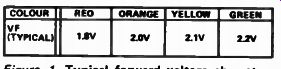
Figure 1 Typical forward voltage
characteristics of standard LEDs with forward current set at 20 mA. When
you use an LED, you have to wire some form of current-limiting device in
series with it. Usually, a resistor can be used for current limiting.
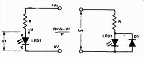
Figure 2 shows how to work out the value of resistance to give a particular current from a specific supply voltage: in practice, ' R' can be connected in either the anode or cathode side of the LED. The higher the operating current, the brighter the LED will glow. Most LEDs will operate safely up to absolute maximum currents of 30 to 40 mA.
You can use an LED as an indicator in an ac circuit by wiring a diode in inverse parallel with it, as shown in
Figure
2. ( Left). Finding the required series resistance from a known supply voltage.
Figure 3. ( Right). Using a LED as an indicator in an ac circuit.
Figure 3, to prevent the LED being reverse-biased. For a given brightness, the value of ' R' should be halved relative to that of a dc circuit.
If an LED is reverse biased, it will avalanche or ` zener' at a fairly low voltage, as shown in Figure 4. Most LEDs have maximum reverse-voltage ratings in the range three to five volts.
These low ratings present a trap for the unwary user, so take heed.
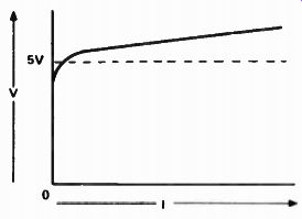
Figure 4. A reverse-biased LED will have characteristics similar to a
zener with a 'knee' around five volts.
Pitfalls
The first practical problem that you'll encounter when using an LED is that of identifying its polarity. Most LEDs have their cathode identified by a notch or flat on the package, or by a short lead. This practice is not universal, however, so the only sure way to identify an LED is to test it in the basic circuit of Figure 2: try the LED both ways round. When it glows, the cathode is the most negative of the two terminals. It is always good practice to test an LED before soldering it into circuit.
The second pitfall concerns the use of those 'cheapo' LEDs that come in Bargain Packs. These are usually advertised as 'second grade' or ' out of spec' devices, but just how out-of-spec they are can sometimes be quite mind blowing. You'll often find that half of the devices in a pack have forward voltages in the range five to eight volts, which makes them virtually useless in many applications.
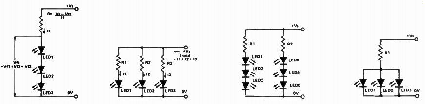
Figure 5. This circuit shows a 0 to 10 V voltmeter using a Siemens UAA170
IC. For correct operation, the forward voltage of each LED must be matched
to within 0.5 V and thus first grade LEDs only may be used.
If you ever need to drive a number of LEDs from a single currently available 'dot' or ' bar' LED-display driver ICs, always check its spec to see if it is sensitive to LED characteristics. The Siemens UAA170 15-LED 'dot' driver, for example, will only function correctly if all LED forward voltages are matched to within 0.5 volts, and can thus be used with first grade LEDs only. Figure 5 shows the circuit of a 0 to 10 volt 16-LED voltmeter using this IC. Driven to it If you ever need to drive a number of LEDs from a single source, take notice of the circuits in Figures 6 to 9. Figure 6 shows how a number of LEDs can be wired in series and driven via a single current-limiting resistor. Note that the supply voltage used here must be significantly greater than the sum of the individual LED forward voltages. This circuit thus draws minimal total current, but is limited in the number of LEDs that it can drive.
The Figure 7 circuit, on the other hand, can drive an unlimited number of LEDs, but is very wasteful of current.
The total current drawn is equal to the sum of the individual LED currents.
Figure 8 combines the Figure 6 and 7 circuits to give the best of both worlds.
The circuit can drive an unlimited number of LEDs, at maximum current economy.
Figure 9 illustrates one of those 'traps for the unwary', or 'what not to do' circuits. This circuit will not function correctly because inevitable differences in the forward voltage characteristics of the LEDs will usually cause one LED to 'hog' most of the available current, leaving little or none for the remaining two.
Figure 6. ( Left). How to determine the series resistor value required for
LEDs wired in series and driven from a single supply.

Figure 7. ( Right). You can drive a whole host of LEDs from one supply rail
- provided you can source the current required.

Figure 8. ( Left). This is a combination of the circuits in Figs 6 & 7.

Figure 9. ( Right) . How NOT to do it - one LED hogs all the current.
Chasers
The highly popular CD401713 decade counter with 10 decoded outputs is widely used for driving LED displays in chaser or sequencer applications. A certain amount of confusion seems to exist, however, concerning the ‘correct' method of connecting the LEDs to the decoded outputs.
The decoded outputs of this CMOS device provide inherent current-limiting under short-circuit conditions. The manufacturers do not quote a maximum short-circuit current value, but practical experience indicates that currents of 10 10-15 mA are commonly available from the ` version of the 4017. A maximum device dissipation per output transistor figure of 100 mW is quoted on some data sheets, indicating that a volt drop up to about seven volts can safely be developed across a 4017 output stage under maximum-current conditions.
Thus the LED chaser circuit of Figure 10, this has each LED connected directly between an output and ground and can safely be used up to maximum supply values of 9 volts. At voltages greater than 9 volts, the circuit of Figure 11, which has a resistor wired in series with each LED, should be used.
Note that the main purpose of these resistors is that of reducing the power dissipation of the 4017B. A variant that is sometimes used is shown in Figure 12a, and can be used with reasonable confidence at supply levels up to 12 volts maximum. Figure 12b shows a possible equivalent of this circuit when it is powered from a 15 volts supply, and illustrates the defect of the design. The action of the 4017 is such that when a given LED is ON, the anodes of all other LEDs are effectively grounded. R1 thus causes the OFF LEDs to be reverse biased. Because of the low reverse-voltage ratings of LEDs, it will often be found that one of the OFF LEDs will Zener at about five volts, giving the results shown in the diagram and possibly causing a destructive power overload in one of the 4017B output stages. Figure 12 thus represents a classic 'trap for the unwary' type of LED circuit.
===========
The LED as a regulator
A LOW NOISE regulator can be made using an LED as the reference element. David Tilbrook used this technique in the Series 4000 moving coil preamp ( ETI-473, Sept '79). The usual reference element for discrete voltage regulators is a zener.
As these devices operate in the reverse- biased mode, they are inherently noisy and will put noise on the regulated supply rail. This is likely to degrade the performance of low-noise, low-level circuits supplied by the regulator.
The circuit of the +/-6V regulated supply for the ETI-473 moving-coil preamp is reproduced here. A red LED operated in the forward-biased mode drops a constant 1.65 V and generates very little noise. The reference LEDs in the circuit here are LED1 and LED2.
Series regulators 013 and 014 regulate the incoming +/- 12V. The potential dividers R21/R23 and R22/R24 divide the voltage present at the output of the regulators and drive transistors 015 and 016, and the LEDs. The base-emitter junction in series with each LED will drop 0.6 V; to this is added the LED forward drop of 1.65 V. Thus, whenever the voltage present at the junction of the voltage divider resistors tries to increase above 2.3 V, 015 and 016 will increasingly conduct, decreasing drive to the bases of 013 and 014 respectively.
Noise on the regulated supply rails is further reduced by the C- R networks, C12/R19 and C13/R20.
===========
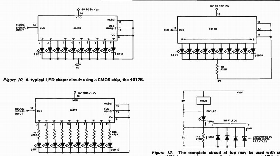
Figure 10. A typical LED chaser circuit using a CMOS chip, the 4017B.
Figure 11. For supplies over 9V, use this circuit instead of Figure 10. LEDs will be biased into their zener region.
Figure 12. The complete circuit at top may be used with supplies up to 12V but contains a trap for the unwary - at 15V, the 'off'