A PRACTICAL GUIDE TO ZENER DIODES – PART 1
In this two-part article we explain how to use this versatile circuit component.
ZENER DIODES - named after Dr Carl Zener - are used primarily as voltage references. They are devices that maintain an almost constant voltage across them despite various changes in circuit conditions.
Externally, Zener diodes look much the same as conventional diodes and are manufactured in axial lead, and stud mounting forms; furthermore Zener diodes are capable of rectifying alternating current into pulsating direct current as are their conventional counterparts.
But unlike conventional diodes, Zener diodes are deliberately intended to be used with the anode connected to a negative potential and the cathode connected to a positive potential.
When connected in this manner, Zener diodes have a very high resistance below a certain, critical, voltage (called, appropriately, the Zener voltage). But if this critical voltage is exceeded, the dynamic resistance of Zeners drop to a very low level. And in this region, essentially constant voltages will be maintained across the Zeners, and these constant voltages will be maintained despite quite large changes in the applied currents.
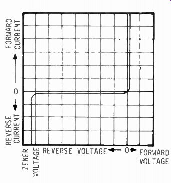
FIG. 1
This characteristic is illustrated graphically in Fig. 1 from which it may be seen that beyond the ' Zener voltage' the reverse voltage remains practically constant despite changes in reverse current.
Because of this characteristic, Zener diodes may be used to pro- vide a constant voltage drop, or reference voltage, across their internal resistance.
Zener diodes are manufactured in a number of wattage ratings and with Zener voltages ranging from 2.7 Volts to 200 Volts. ( In practice, Zener diodes with ratings exceeding 30 Volts are rarely used.)
THE BASIC CIRCUIT
A basic voltage regulator circuit, using one resistor and one (idealized) Zener diode, is shown in Fig. 2. In the example shown, the Zener diode is rated at 5.6 Volts and the applied voltage V in is 8.0 Volts. With no load applied to the output terminals, 5.6 Volts will be dropped across the Zener diode and the remaining 2.4 Volts will be dropped across resistor R5.
If the input voltage is now changed, say, from 8.0 Volts to 9.0 Volts, then the voltage drop across the Zener will still remain at its nominal 5.6 Volts but the voltage drop across R, will increase, from 2.4 Volts, to 3.4 Volts.
The voltage drop across the ( ideal) Zener will remain constant.
In practice, the voltage will increase slightly due to the dynamic resistance of the Zener. (The method of calculating the change in Zener voltage is simply to multiply the dynamic resistance of the Zener diode by the change in Zener current.) The resistor R1, in Fig. 2, represents an external load. If this load is connected across the circuit, then some of the current that was flowing through the Zener will now pass through the load. Providing the current in R5 is greater than the load current, some current will still pass through the Zener and a substantially constant voltage will be maintained across the Zener/load.
The series resistor R5 is selected so that the minimum current passing through the Zener. is not less than the level required for stable regulation.
This level begins just below the 'knee' of the reverse voltage/reverse current curve ( as shown in Fig. 1). Curves such as this are available for all makes and types of Zener diodes.
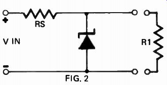
FIG. 2
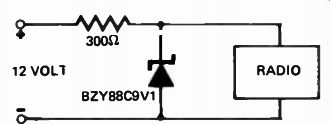
FIG. 3
It is also necessary to ensure that the value of R, is such that current flow through the Zener diode cannot exceed its specified power rating: which is the Zener voltage multiplied by the Zener current. In the circuit shown in Fig. 2, maximum current will flow through the Zener diode when the load is disconnected.
- The design procedure for this circuit is quite simple.
1. Specify the maximum and minimum load current ( l i), say 10 mA and 0 mA.
2. Specify the maximum supply voltage that is likely to occur (say, 12 Volts), but ensure that 'the minimum supply voltage will always be at least 1.5 Volts higher than the Zener voltage of the diode to be used.
3. In the circuit shown in Fig. 2, the required output voltage, and hence the Zener voltage, is 5.6 Volts, and the specified minimum Zener current is 100 microamps. Thus the maximum Zener current is 100 microamps plus 10 milliamps - which is 10.1 milliamps.
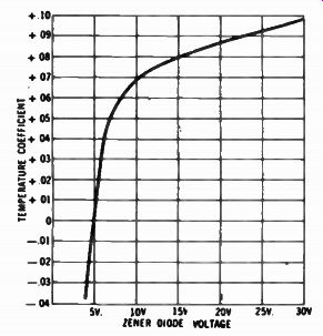
FIG. 4
4. The series resistor Rs must conduct 10.1 mA at the lowest input supply voltage: and so allowing 1.5 Volts minimum voltage drop across 13, (i.e. input voltage minus Zener voltage): Rs 1.5
- 10.1x 10^-3
= 148.5 ohms
5. The value of R, is thus 148.5 ohms, and the nearest preferred value to this is 150 ohms.
6. At the maximum supply voltage (12 Volts), the voltage drop across Rs is I, Rs, ( I, being Zener current): thus I, (12 - 5.6) mA
150 = 42.6 mA
7. This is the maximum current that will flow through the Zener at any time, i.e., maximum input voltage and zero external load. The power dissipated by the Zener under these conditions is: IzVz
= 5.6 x 42.6
= 238 mW.
8. Having calculated that the correct value for Rs is 150 ohms, and that the Zener diode must be capable of dissipating 238 mW all that remains is to choose the correct type of 5.6 Volt Zener. This is, in fact, well within the capabilities of most small Zener diodes which are generally rated at 400 mW.
A PORTABLE RADIO IN YOUR CAR
A practical example of the circuit described above is illustrated in Fig. 3.
This shows how to run a transistor radio from your car's power supply.
The voltage required for the radio is 9 Volts - and the nearest Zener diode to this is 9.1 Volts.
The maximum current drawn by the radio is measured at - say - 10 mA, and, as the load does not vary greatly, this is also the minimum current. ( As 10 mA is well above the ' knee' current of most small diodes, the addition of a minimum operating current is not required.) The maximum supply voltage is around 14 Volts, ( when the battery is fully charged). Thus the series resistor Rs must conduct 10 mA at the lowest supply voltage ( 12 Volts) and its value is calculated by:
Rs 12 - 9.1
- 10 x 10
= 290 ohms
At the maximum supply voltage ( 14 Volts) the voltage drop across R5 is (14 - 9.1)
FIG. 5 FIG. 6 FIG. 7
A PRACTICAL GUIDE TO ZENER DIODES
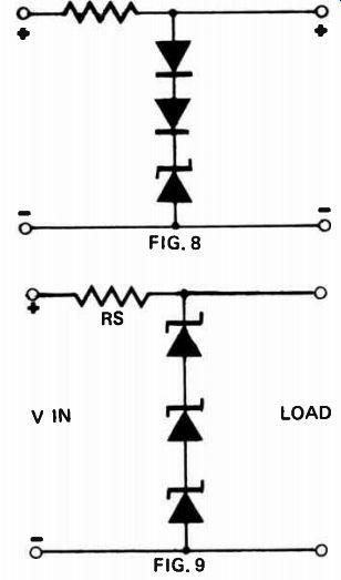
FIG. 8 ; FIG. 9 The maximum power dissipated in the Zener is: 9.1 x 16.8 mA =
152.8 mW
This is well within the capabilities of a standard 400 m1/11 Zener, such as a BZY 88 C9V1.
TEMPERATURE DRIFT
Although Zener diodes are relatively immune to changes in supply voltage and load, they are to varying extents affected by changes in ambient and operating temperature. Fig. 4 shows a typical Zener diode temperature coefficient curve, and, as can be seen, the coefficient, although approaching 0.1% per degree Centigrade at the higher voltages, passes through zero at about 5 Volts and then becomes negative for lower voltages, reaching -0.04%/C0 at approximately 3.5 Volts.
The transition between a negative and a positive temperature coefficient is not well defined and a 5.6 Volt Zener may have either a positive or negative coefficient depending upon the current flow through it. But by careful control of the operating current it is possible to hold a standard 5.6 Volt Zener diode to a temperature coefficient of ± 0.001% over a temperature range of +250C to +750C (Fig. 5 refers). The only difficulty is to provide a constant current source for the Zener diode. One method is to use a 10 Volt Zener diode to act as a regulator for the reference diode. ( Fig. 6). The current limiting resistor between the two diodes should have a negative temperature coefficient to compensate for the positive (+0.07%/0C) temperature coefficient of the 10 Volt Zener.
A second method of stabilizing the current to the Zener diode is shown in Fig. 7. In this arrangement two 5.6 Volt Zeners, each having practically zero temperature coefficient, in turn stabilize the current through the voltage reference.
Another approach to compensation for temperature change is shown in Fig. 8 where the temperature coefficient of forward-biased silicon diodes is used to counteract the opposite temperature coefficient of the Zener diode. This method may be used to compensate for voltage drift over quite wide ranges of both temperature and voltage, Zener voltage stabilities of 0.01% are readily achieved.
As can be seen. from Fig. 4, the temperature coefficient of Zener diodes increases considerably at the higher Zener voltages. An alternative method of temperature stabilizing to that shown in Fig. 8, is to use a number of 5.6 Volt Zeners in series. (Fig. 9).
TEMPERATURE SENSING
The apparent disadvantage of a Zener diode's temperature coefficient may be put to a useful purpose in the form of a temperature sensing device. Fig. 10 shows how a bridge consisting of two resistors and two similar Zener diodes may be constructed so as to indicate a temperature level when one of the diodes is held at a reference temperature and the other is subject to the conditions to be monitored. The average small 10 Volt Zener has a temperature coefficient of +0.07%/0C - this corresponds to 7 millivolts per 0C change. The sensing element will, therefore, indicate an imbalance of 0.7 Volts when undergoing a 1000C temperature change.
NON-STANDARD VOLTAGES
Occasionally it is necessary to obtain a regulated voltage other than that obtainable from a single Zener, this ...
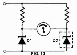
FIG. 10 RS V IN 100V dc (27V) (12v)
(6.8V) D (3.9V)
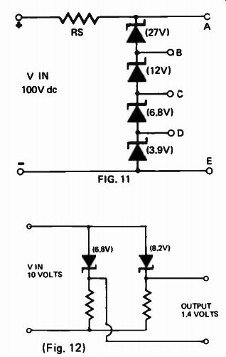
FIG. 11 VIN 10 VOLTS (8.2V); (Fig. 12) OUTPUT 1.4 VOLTS
... can be achieved by connecting a number of Zener diodes in series ( Fig. 9). The diodes need not have equal breakdown voltages since the arrangement is self equalizing.
However, the power handling ability of each diode should be the same. In addition, the current ranges should be similar or the loads so arranged to avoid damaging any of the diodes.
A group of Zener diodes may be used as a voltage divider to obtain several regulated voltages simultaneously. (Fig. 11).
This circuit may be used as a meter or ' scope calibrator. The four diodes shown in the circuit will supply 10 possible voltages:-
Voltage
3.9 6.8 10.7 12.0 18.8 22.7 27.0 39.0 45.8 49.7
Terminals
E - D C - D C - E B - C B - D B - E A - B A - C A - D A - E
It may also be necessary at times to provide a regulated voltage lower than the 2.7 Volts minimum normally obtainable from a Zener diode.
Voltages lower 2.7V may be obtained by using the difference in potential between a pair of Zeners, (Fig. 12). The temperature compensation of this circuit is excellent, for both Zener diodes tend to drift in the same direction, thus maintaining the difference voltage.
The second part of this series describes various ways in which Zener diodes are used in both ac and dc applications.
============
A PRACTICAL GUIDE TO ZENER DIODES – PART 2
THE ZENER diode is generally associated with dc applications, such as the control and regulation of dc power supplies. Most Zeners are in fact used for this purpose but nevertheless they have many uses in ac, audio, rf, and ac control systems.
When supplied with alternating current and connected as a shunt regulator (Fig. 13), the Zener diode will limit both the positive and negative halves of the ac cycle. The diode conducts almost immediately after the signal passes through zero and into the negative segment. On the positive half cycle, the diode does not conduct until the applied voltage reaches the Zener voltage (Fig. 14). The result is a non-symmetrical square wave. Asymmetry can be improved by using high input voltages, but can never be completely eliminated unless two shunt connected diodes are employed in a back-to-back configuration. ( Fig, 15). The Zener diode configuration shown in Fig. 15 is often used to provide stabilized filament supply voltages - especially to oscillator circuits and dc amplifiers. When using Zeners in this application bear in mind the ratio of average to peak Zener current. A figure of 0.6 is satisfactory.
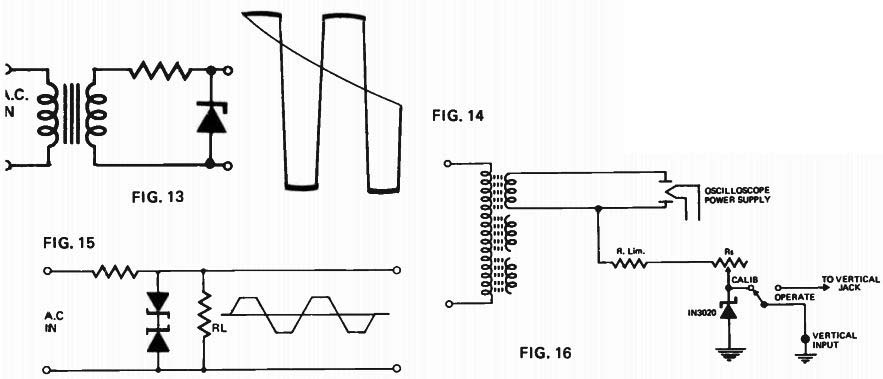
FIG. 13, FIG. 14. FIG.
15, FIG. 16
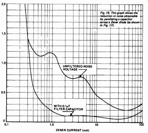
Fig. 18. This graph shows the reduction in noise obtainable by paralleling a capacitor across a Zener diode (es shown in Fig. 17).
Zener diodes may also be placed in the primary side of a step-down (or step-up transformer). When connected in this manner the diodes will regulate all associated secondary windings. The arrangement does require high voltage rated Zeners and is sometimes rather costly - however it is often used when high voltage secondary supplies need rudimentary stabilization.
Where power consumption is a prime consideration on ac power circuits, the Zener load resistor ( RS) can be replaced by an inductance or capacitance. The device selected should have a reactance approximately the same as the calculated value for RS at the supply frequency.
OSCILLOSCOPE CALIBRATOR
A single Zener diode may be used as an inbuilt oscilloscope voltage calibrator that is independent of line voltage variations. Figure 16 shows how simply this facility may be incorporated in practically any oscilloscope. A selected 10 Volt Zener may be used to provide a calibration voltage of one volt per division.
ZENER NOISE VOLTAGES
As with neon regulator tubes, Zener diodes generate noise voltages. With Zener diodes, these voltages are associated with junction avalanche effects, and may vary between 10 uV and 1 mV depending upon the Zener type and voltage rating.
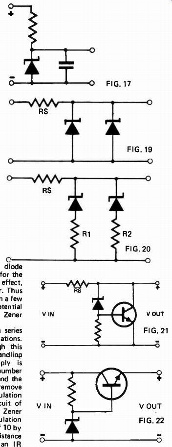
But unlike neon regulator tubes - where the incorporation of parallel filter capacitors is an excellent ( if unintentional) way of making a relaxation oscillator -- a Zener diode may be suppressed by adding parallel capacitance of 0.01 to 0.1 uF. This will reduce the noise voltage by a factor of at least 10 and yet maintain completely stable operation. ( Figs. 17 & 18).
THE ZENER DIODE AS A FILTER
The Zener diode will respond to ripple voltages in much the same manner as it does with slow voltage variations. It has a very low dynamic impedance and thus reacts in much the same way as a filter capacitor.
Excellent power supply filtering can be obtained by connecting a Zener diode (having a Zener voltage equivalent to the ripple trough) across the load. In most circuit applications this will be as effective as adding a smoothing capacitor of several thousand microfarads capacity, and will provide a considerable reduction in the level of ripple superimposed on the dc output.
INCREASING POWER HANDLING
Parallel connection is one way of increasing the power capabilities of Zener diodes. But a simple parallel connection ( Fig. 19) is not practicable, for the Zeners will rarely be sufficiently well matched to conduct at exactly the same voltage. But by including very low resistance trimming resistors, the current levels can be matched so that both Zeners carry substantially equal amounts of the total current. ( Fig. 20) Although, as shown above, Zener diodes can be paralleled in order to increase their load carrying capacity it is usually more practicable to use a series or shunt transistor circuit with a Zener diode providing a voltage reference. This configuration will not only improve the power handling capability by a factor of ten or so, it will also improve the regulation of the circuit by an amount equal to the current gain of the transistor.
A simple Zener controlled shunt regulator is shown in Fig. 21.
The shunt regulator is very suitable for experimental and instructional use as it is totally short circuit proof. But, since maximum transistor current flows at zero load ( and vice versa), it is also very inefficient, and for applications where power availability is limited the series transistor configuration is preferable.
A series regulator is shown in Fig. 22.
In this circuit the Zener diode establishes a reference voltage for the series transistor, which, in effect, operates as an emitter follower. Thus the emitter voltage is held within a few tenths of a volt of the base potential (which is determined by the Zener diode). Thus the transistor acts as a series element to absorb voltage variations.
All load current flows through this series transistor. The power handling ability of this type of supply is determined entirely by the number and type of transistors used ( and the ability of the heat sink to remove heat). Figure 23 shows the regulation obtained from the simple circuit of Fig. 22 which uses a 4.7V 1 4W Zener and a 1k series resistor. The regulation may be improved by a factor of 10 by substituting a low dynamic resistance 4.7V 3.5W Zener ( we used an IR 1N1589) for the '4W device.
This circuit ( Fig. 22) can provide a variable voltage regulated output by connecting a 1k potentiometer across the Zener diode. The variable reference voltage is then applied to the base of the series transistor. However, this modification reduces the degree of regulation due to the shunting effect of the potentiometer. A better system is to switch different Zener diodes into the circuit for different voltage outputs.
Fig. 19- 25.
CONSTANT CURRENT REGULATION
A simple Zener-regulated constant current supply can be built using a single transistor as a variable series resistor. Figure 24 shows how it is done. Two circuit paths exist; one through the Zener diode which is in series with the bias resistor, and the other through R1, R2 and the 2N301 series transistor. Any change in the current through R3 causes a change in bias, the series transistor thus changes resistance to correct the current flow.
In operation the current will remain substantially constant (within about 10%) from a short circuit to a 400 ohm output load. A graph of the output characteristics is shown in Fig. 25.
LOGIC CIRCUITS In many ways a Zener diode
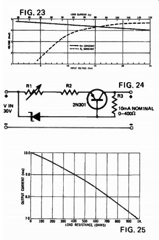
FIG. 23
FIG. 24
FIG. 25 resembles a switch, and is therefore often used in computer and instrumentation logic circuitry.
The advantage of Zener diodes for this purpose is their extremely rapid operation when switching around their avalanche point. Whereas germanium or silicon diodes are limited to data rates of less than 2.5MHz (due to storage of minority carriers) Zener diodes switching about their avalanche point have switching times practically equal to their relaxation time. For silicon this is 10-9 seconds.
A typical AND gate, using two 6.8V Zener diodes is shown in Fig. 26. The positive 12 Volt bias is applied to both cathodes through the common load resistor, maintaining the diodes in avalanche condition. If a positive pulse is now applied to input A, the associated Zener will be gated out of the avalanche region. But due to the low impedance of the parallel connected Zener (associated with input B), the output (point A.B) remains clamped at 6.8 Volts. The same circuit conditions apply if a pulse is applied solely to input B. However if a pulse arrives simultaneously at points A and B, both Zeners will be gated out of the avalanche region and the output voltage will rise from 6.8 Volts to the 12 Volt supply potential during the time that the pulse is coincident at the two inputs. Thus a positive pulse is produced coincident with the input pulse. Negative input pulses will not affect the circuit.
Figure 27 shows how a similar technique may be used to provide an OR function. In this configuration a pulse applied to either input will produce a pulse at the output.
SORTING
In the circuit shown in Fig. 28 the relays will be progressively energized as the input voltage increases. This circuit is often used for voltage controlled sorting. The relay contacts may be arranged to open chutes and illuminate indicator lamps for rapid sorting.
OVERVOLTAGE PROTECTION
The voltage sensitive characteristic of Zener diodes can be combined with the current sensitive characteristic of fuses to protect circuit components from overvoltage surges, whilst at the same time eliminating the ' nuisance' fusing that occurs when a fuse too close to the operating current is used.
By connecting a Zener diode of the correct voltage rating across the load, a fuse adequate to carry the normal load operating current for long periods may be used. But if the input voltage increases - and so exceeding the Zener breakdown voltage - the Zener diode will conduct. The sudden increase in current will blow the fuse practically instantaneously. ( Fig. 29). A similar circuit may be used in conjunction with a circuit breaker rather than a fuse.
UNDERVOLTAGE PROTECTION
In some applications it may be necessary to disconnect a load from the mains supply if the supply voltage falls below critical level. A simple circuit that will provide this function is shown in Fig. 30. The series resistance R1 is chosen so that at normal operating voltages the Zener diode is broken down and sufficient current flows to hold the relay closed.
When the supply voltage falls below the desired level, the Zener ceases to conduct and the relay drops out. The addition of the Zener diode to this circuit provides an accurate reference point, increasing reliability and eliminating the need for specially selected relays for different voltages.
DUAL VOLTAGE SUPPLY
Most logic circuitry needs a dual power supply - ( one positive and one negative with respect to zero). The useful, but little known circuit shown in Fig. 31 can supply a dual output of balanced or unbalanced voltage from a single ended power supply. Zener diodes should be chosen to suit the voltages required.
Full details of operating characteristics of Zener diodes can be obtained from most semiconductor manufacturers.
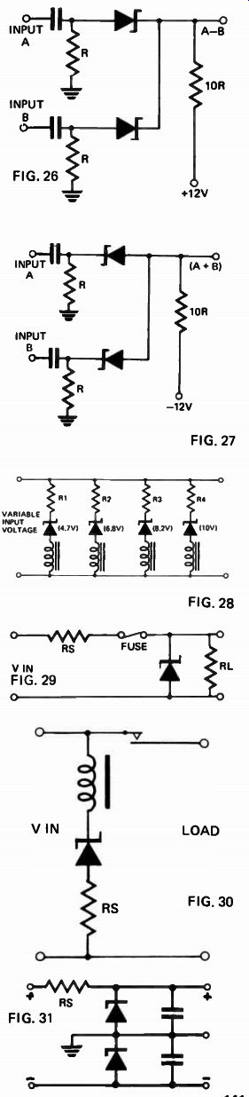
FIG. 26 - FIG. 31