We have studied the various sections of an FM receiver in considerable detail. :Now we shall observe how these principles are applied to a complete receiver. It will be found, after examination of the many receivers which are available, that they differ markedly in essentially two respects-type of R.F. tuner employed and the circuitry of the FM detector or discriminator.
The remaining sections of the receivers, which include the I.F. stages, the audio amplifiers, and the power supply, are designed along closely similar lines. Although few of these stages are exact duplicates of each other, complete understanding of the circuit in one receiver will lead readily to comprehension of corresponding circuits in other receivers.
With regard to discriminators, all of the presently available commercial FM receivers employ either a Foster-Seeley discriminator or some form of ratio detector. The other two types of FM detectors which have been de scribed have appeared only in the sound section of television receivers.
Their quality has apparently not been regarded as good enough for a commercial FM receiver. Hence, we will not encounter these detectors in our examination of commercial FM receivers here.
We will examine in this Section four receivers which are typical. The first is a low-cost receiver capable of receiving either AM or FM signals.
The second is an FM tuner designed to receive FM signals only, amplify these signals, and then demodulate them, and equipped with an external amplifier system, to drive a loudspeaker. The third is an AM, FM tuner performing the same functions as the foregoing FM tuner, except that it covers both commercial broadcast bands. In addition, it possesses other features which add to its versatility. The fourth is a complete AM, FM receiver, containing both a tuner and a power amplifier. Only an external speaker is required to provide a complete high-fidelity system. The unit also possesses an internal preamplifier, enabling records to be handled as well. Equalization, loudness correction and a continuously-variable bass treble tone control are also available in this receiver. With these four receivers as a background, the reader will be able to analyze almost any type of FM or AM, FM combination receiver he is likely to encounter.
A Low-Cost AM, FM Receiver. A low-cost AM, FM receiver, housed in a small table model cabinet, is shown in Fig. 12.1. A total of seven tubes perform all the functions needed to deal with both AM and FM signals. A 4 x 6 inch speaker reproduces the sound output. No power transformer is employed, the d-c voltage being developed by a small selenium rectifier. This permits the receiver to operate from either 120 volt a-c or d-c power line. A slide-rule type of tuning dial carries one set of markings for the FM channel and another set for the AM channel. The band to be received is selected by a two-position switch marked " FM" and " AM.".
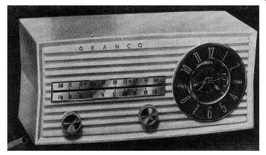
Fig. 12.1. The Granco Model 770 AM, FM receiver.
The FM Section. The tubes in this section are: An FM, R.F. amplifier (12BA6), an FM mixer (using one-half of a 12AT7), an FM oscillator (using the other half of the 12AT7), two I.F. amplifiers each using a 12BA6, a ratio detector (19T8), an audio frequency amplifier using the triode section of the 19T8, and a 35C5 output amplifier. Of these tubes, the two I.F. amplifiers, the A.F. amplifier, and the audio output serve both FM and AM channels. The remaining ones deal solely with FM. Incoming FM signals are developed across L1, a broadly tuned air-core coil, and applied to grid No. 1 of the FM, R.F. amplifier, V1. Here they are amplified, appearing across the output load inductance, L2. Since the R.F. amplifier is un tuned, all of the signals of the FM band are received equally well. however, the signal reaching the mixer, V2A, is determined by the R.F. tuning circuit, L10, C7, and the small trimmer capacitor (T) shunting C7. C7 is mechanically ganged to 0 10, the FM oscillator tuning capacitor, and to C8 and C9. The latter two capacitors tune the AM ferrite rod antenna (Ls) and the AM oscillator. In actual construction C7 and C10 differ markedly from C8 and C0. The first two capacitors are coaxially shaped units in which one cylinder moves within another cylinder, the two being separated by a glass dielectric. (This type of variable capacitor was previously discussed in Section 5.) C8 and C9, on the other hand, are conventionally-shaped capacitors in which each has a variable set of plates which mesh with a fixed set of plates. All four units, however, are mechanically ganged together so that one front panel knob controls them.
Feeding into the FM mixer is another signal developed by an ultraudion oscillator. This oscillator operates above the incoming signal, combining with it in the mixer to form the 10.7-mhz I.F. voltage. This signal is developed across the primary of T1 and inductively coupled to the secondary where it is applied to the control grid of the first I.F. amplifier, V4. It will be noted that the secondary of the 455- khz AM, I.F. transformer T2 is in series with the secondary of T1. No difficulty is caused by this arrangement because this winding of the 10.7 -mhz transformer possesses negligible inductance at 455 khz. By the same token, the by-pass capacitor of the 455- khz transformer permits the high frequency signals to pass around this winding.
V4 amplifies the FM signal and then transfers it by means of Ts to the grid of the second FM, I.F. amplifier, Ve,. Additional amplification occurs here, after which the signal is forwarded to Tr, and, from here, to an unbalanced ratio detector. The stabilizing network in the detector is formed by C2 and R14. C19 is placed in parallel with C2 to offset the appreciable inductive reactance that is common to electrolytic capacitors such as C2.
The audio output of V3A travels through the de-emphasis network, R12 and C21 , down to position 1 of switch S1. This is the previously mentioned two-position front panel switch which enables the set user to select either FM or AM. The switch, as shown, is in the FM position; therefore, the signal received from the ratio detector will pass from contact 1 to contact 2 and from here to the volume control and the A.F. amplifier. The triode section of the 19T8 serves as an audio voltage amplifier, amplifying the voltage received from the movable arm of the volume control and then forwarding it to V7, the audio output stage. Here sufficient power is developed to drive a 4 x 6 inch loudspeaker.
A small amount of negative feedback is obtained from the secondary of the output transformer and applied to the bottom of the volume control.
This stabilizes the audio frequency system and tends to reduce the distortion produced here.
When switch S1 is in the FM position, contacts 4 and 5 are electrically connected and the 80 volts applied to contact 5 reach the FM oscillator, FM mixer, and second FM, I.F. amplifier. These stages serve only the FM signals. When switch S1 is in the AM position, the B+ voltage is removed from these stages, inactivating them.
The power supply, serving all sections of the receiver, consists of a selenium rectifier and a fairly simple filter network. Output voltages of 110 and 80 volts are developed. The filaments of each of the seven tubes are series-connected in the order shown. Appropriate dropping resistors are inserted in the circuit to provide the proper voltage distribution within the filament network; in addition, by-pass capacitors are shunted across various points in this chain to make certain that R.F. or I.F. signals do not travel from one stage to another through the filament circuit. If this is permitted, regeneration may result.
The AM Section. AM signals are picked up by a ferrite rod antenna, L3, and applied to the signal grid (No. 3) of the 12BE6 AM converter. At the same time, the control grid (No. 1) and cathode of this tube serve as an oscillator, using the tuning circuit formed by L4, C0, C13, and a trimmer capacitor (T) to develop the necessary oscillations for the mixing operation.
An output I.F. signal of 455 khz is developed in the plate circuit of V 3, across the primary winding of T2. From here, it is coupled to the secondary winding and the control grid of V 4. After the signal is amplified, it is placed across the primary winding of T4 , inductively coupled to the secondary winding, and then rectified by the cathode and control grid of V 5. Since we are now operating on AM, switch S1 has been rotated one position counter clockwise and the B+ voltage which was previously applied to the plate of V 5 has now been removed. The same is true of the screen grid. The AM detector load resistor is R10 and the audio signal which appears here is brought to position 3 of S1. From position 3, it travels to position 2 and from here to the volume control. From this point, the audio signal is amplified by V6, then by V 7, and finally applied to the loudspeaker.
Resistor Ro and by-pass capacitor C14 filter out the audio variations and permit the average d-c voltage developed across R10 to serve as an A.V.C. voltage for V 4 and the signal grid of V 3 . This arrangement, it will be seen, is a conventional A.V.C. network and functions in the same manner as it does in any AM receiver. In the AM position, contacts 5 and 6, switch S1, are electrically connected and this enables the 80 volts from the power sup ply to power both the screen grid and plate of V 8. At the same time, V 1, V 2A, V 2B, and V 5 are rendered inactive.
From this analysis, it can be seen that both the AM and the FM circuits are straightforward and neither contains anything that has not been previously discussed. One interesting feature is the power line antenna.
The power line, in addition to its regular function, is employed also as an antenna and FM signals which it captures are capacitance-coupled to a short section of wire which is connected to the antenna input terminals.
This provides satisfactory FM reception for all moderate and strong signals. If it is desired to extend the reception range and pick up weak signals, an outside antenna. is employed. In this case, the power line antenna is simply set aside.
Alignment Procedure. The alignment procedure for both AM and FM sections of this receiver follows a standard pattern. Allow the set to warm up 15 to 20 minutes before beginning the alignment. Always align the receiver using the lowest signal from the signal generator which will give a usable reading on the indicating device. The volume control should be set to the maximum position. The manufacturer recommends alignment of the AM circuits first. Since this is a transformerless receiver, either an isolation transformer should be employed between the receiver and the power line or a 0.1-mf capacitor should be connected in series with the ground side of the signal generator and the B- point of the receiver. These precautions should be carefully observed; otherwise the danger exists of short-circuiting either the receiver or the signal generator with disastrous results.
AM Alignment. Connect the signal lead of the signal generator to pin 7 of the 12BE6, V3, through a series .1-mf capacitor. The low side of the signal generator connects to the receiver chassis. Set the signal generator to a frequency of 455 khz, modulated by a 400-cycle signal. The band switch of the receiver is turned to the AM position and the tuning capacitor is fully opened. Also, an output meter is connected across the voice coil of the speaker.
With equipment and receiver in operation, adjust the primary and secondary cores of transformer T 2 and T 4 for maximum indication on the output meter. Next, fashion a loop of five to ten turns of wire and connect the open ends of this loop to the signal generator. Position the loop so that it is close to the ferrite antenna rod of the receiver. Set the signal generator frequency to 1650 khz. Some indication of signal should appear on the output meter. If none is visible, bring the loop closer to the receiver until an indication is obtained. Then adjust the trimmer capacitors of G8 and G9 for maximum output meter reading. Next, reduce the signal generator frequency to 610 khz and tune the front dial to the same frequency. Adjust the core of L4 for maximum output on the meter. Do this while slightly rocking the tuning capacitor back and forth to make certain that the peaking is done at the proper point.
This completes the adjustment of the AM section of the receiver. Various signals should be tuned in now to make certain they can be received properly.
FM, I.F. Alignment. As a first step in the FM, I.F. alignment, connect two matched 100,000 ohm resistors (plus or minus 1%) in series from point A (Fig. 12.2) to the chassis. The junction of these two resistors is alignment point C. The signal generator has its signal lead connected to pin 7 of V 2A. This is done through a .01-mf capacitor. The low side of the signal generator connects to the chassis. Set the signal generator to a frequency of 10.7 mhz, unmodulated. Turn the band switch to the FM position. A VTVM is used as the indicator, with its d-c probe going to point A. The common lead of the VTVM connects to the chassis. As a final preparatory step, the front dial is set to a point where no interference is heard.
Now, adjust the following cores for maximum indication on the meter: the primary core of T5, the primary and secondary cores of T3, and the primary and secondary cores of T1. These should be turned carefully to make certain that maximum indication is obtained. Next, the d-c probe is moved to point Band the common lead of the VTVM is shifted to point C. Rotate the secondary core adjustment of T5 until a zero reading is obtained on the meter. This zero reading should be between a positive reading when the core is rotated in one direction and a negative reading when the core is rotated in the opposite direction. This is similar to the method previously discussed.
This completes the complete alignment of the FM, I.F. system and ratio detector.
FM, R.F. Alignment. The signal generator is brought now to the input antenna terminals and each lead is connected to an antenna terminal through a 150-ohm resistor. The signal generator is initially set for a frequency of 108 mhz. The front panel dial is turned to the same frequency. The d-c probe of the VTVM is connected to point A and the common lead of the instrument is connected to the chassis. Then, the trimmer capacitor across C7 and the trimmer capacitor across 0 10 are each adjusted for a maximum reading of the meter.
The signal generator frequency is turned next to 88 mhz and the front panel dial is changed to suit. L10 and L11 are adjusted by either compressing or expanding the coil turns until maximum deflection is obtained on the VTVM. This should be done very carefully because not much positional change is needed to produce a marked change at the meter.
The alignment of the entire FM section of the receiver is completed now and stations should be tuned in at various points on the dial to make certain that every adjustment has been properly made. Note that nothing is done to coils, L1 and L2. These serve not as tuning coils, but as loads for their respective circuits--L1 for the antenna and L2 for V 1 FM Tuner. A tuner designed to operate only in the FM band, 88 to 108 mhz, is shown in Fig. 12.3. Seven tubes are employed, six in the signal circuits and one in the a-c power supply. Two outputs are provided: one at low level which is not affected by the volume control on the tuner; and the other at high level which is controllable. Overall sensitivity of the tuner is high enough to permit operation with an indoor antenna made up of 300-ohm twin lead, if reasonable signal strength is prevalent in the area. If the signal level is low, an outdoor antenna is recommended.
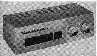
Fig. 12.3. The Heath FM tuner, :Model FM 3A. (Courtesy Heath Co.).
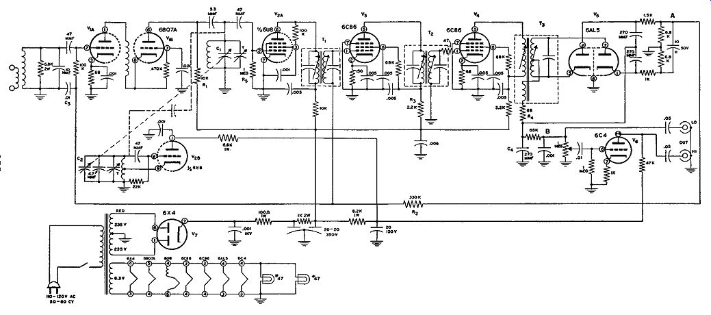
Fig. 12.4. Schematic diagram of the Heath FM tuner shown in Fig. 12.3.
A schematic diagram of the tuner is shown in Fig. 12.4. The sequence of stages is conventional, starting with an R.F. amplifier. However, this amplifier is of the cascode type to provide high R.F. gain and to reduce oscillator leakage to the antenna. A 6BQ7 A twin triode is employed in this circuit. The incoming signal is received by an antenna transformer whose purpose is to match the input impedance of the first triode to the 300-ohm twin lead transmission line. (Input impedance of nearly all commercial FM receivers and tuners is currently established at 300 ohms.) The antenna coils are made broadly resonant with the 10-mmf capacitor and 6800 ohm resistor so that any signal in the FM band can be received. Automatic gain control (A.G.C. or A.V.C.) is applied to the control grid of VIA, This makes it necessary to feed the signal from the antenna coil to the grid through a 47-mmf capacitor. The capacitor will pass the R.F. signal, but block the d-c voltage from the antenna coil and ground.
The first half of the 6BQ7 A tube acts as a conventional triode voltage amplifier. Its plate load is made up of the plate resistance of the second half of the tube which is in series with the first half and the 10,000-ohm resistor, R1. Voltage amplified by the first half of the tube is conducted through a neutralizing choke to the cathode of the second half, causing this element to swing by approximately the same amount. The neutralizing choke resonates with the circuit and tube capacitance in the middle of the F-11 band, providing added gain to the stage and preventing oscillation. In the second section of the 6BQ7 A, the grid is at R.F. ground potential, while the cathode potential is varied. Loading for the second half of the 6BQ7 A is the 10,000-ohm resistor, R1, and the R.F. tuning circuit that follows it. As indicated earlier, the main advantage of the cascode circuit is low noise and a gain equivalent to that of a pentode.
The mixer which follows V1 uses the pentode section of a 6U8. The triode section of this tube is connected as a Hartley oscillator, and the frequency of the oscillator is 10.7 mhz higher than the incoming frequency. Energy from the oscillator is shown in Fig. 12.4 as being capacitatively coupled to the mixer. This is true; however, an actual coupling capacitor (as the dia gram appears to indicate) is not used. Instead, after the circuit is wired, the 47-mmf capacitor in the oscillator grid circuit is physically pressed close to the 47-mmf capacitor connected to the control grid of V2A. This close positioning creates sufficient capacitance between the oscillator and mixer circuits to enable the proper amount of energy to pass from one to the other.
It is interesting to note that V2A uses contact bias. If the cathode of a tube is tied directly to circuit ground and the grid is returned to ground through a high resistance (here, 1 meg) a very small amount of current will be drawn by the grid. This current will be limited by the resistor, however, and a slight negative voltage will appear at the grid. Biasing in this manner is useful where the cathode impedance must be kept low and the signal level is also low.
Two stages of I.F. amplification are employed. The 6CB6's are high gain tubes, providing the signal with considerable amplification. The I.F. transformers, of which there are two, each have adjustable iron cores for peaking the primary and secondary windings to 10.7 mhz.
A balanced ratio detector follows the second I.F. The 10-mf capacitor with the two 6800-ohm resistors to which it is attached serve as the amplitude stabilizing elements which are chiefly responsible for the AM rejection properties of this detector. The 1500-ohm and 1000-ohm resistors in series with the diode sections of the 6AL5 help to maintain current balance in the circuit. Audio, from the tap on the detector transformer secondary, is passed through a 68-ohm resistor and a 270-mmf capacitor network which by-passes all remaining I.F. signal to ground, leaving only the audio signal.
This is next passed through a 68,000-ohm resistor and a .001-mf capacitor de-emphasis network. The audio signal appears across the 1-megohm volume control. The low-level output signal is taken from the fixed resistance terminals of the control; hence, the control has no effect on this output. output from the variable tap is connected through a 0.01-mf capacitor to the grid of the 6C4 audio amplifier.
The 6C4 stage is a conventional audio amplifier. Since the cathode resistor is unby-passed, generation or negative feedback results. This reduces stage gain. However, it also reduces noise and distortion and, in this sense, is useful. A fairly low value of plate load resistance keeps the output impedance low. This also reduces hum pickup in the interconnecting audio cable and minimizes high-frequency loss. However, since this output impedance is higher than that provided by a cathode follower, the length of the cable should be kept as short as possible.
A.V.C. bias is obtained from the stabilizing network in the ratio detector and fed to the control grids of V3 and V1A.
The system functions in exactly the same manner as the A.V.C. network in an AM radio receiver.
Note, however, that, because V1A and V1B are in series with each other, varying the grid bias on V iA varies the current through both sections of V 1, In essence, then, we are controlling the gain of both triodes.
The power supply has a 6X4 full-wave rectifier and a three-section R-C filter. Output B+ voltages of 175 and 100 volts are produced.
FM Receiver Sensitivity. In recent years, FM set manufacturers have established a method of indicating receiver sensitivity by giving the number of microvolts required at the input terminals to produce a certain amount of output quieting. For the present receiver, the manufacturer states that 5 microvolts are required for 20-db quieting. Eight microvolts are needed for 30-db quieting.
This method of designating receiver sensitivity serves to indicate the relative freedom of a receiver from objectionable internal noise during pauses in modulation when receiver noise is least likely to be masked by the modulation of the broadcast. Internal noise in the receiver consists largely of the noise generated in the R.F. amplifier and mixer and in the resistors associated with these stages. For those readers who may wonder how the quieting figure is obtained, here is the procedure recommended by the Institute of Radio Engineers. An FM signal generator is connected to the receiver and the output level is set initially for about 0.001 volt (1000 microvolts). The generator is adjusted for a deviation of 30% of 75 khz.
This would be about 22.5 khz and the frequency will change back and forth at the rate of 60 hz. At the output of a receiver tuned to the signal, the 60- hz note would be heard. The volume control of the receiver is adjusted to some convenient level well below the audio overloading point.
The modulation switch is turned off and on alternately while the signal output of the generator is reduced gradually until a point is reached at which there is a 30-db voltage difference (voltage ratio of 31.62) in receiver output between the time when the signal is modulated and when it is unmodulated. This value of input signal is the quieting figure. Obviously, the smaller the input signal, for a specified quieting figure, the more desirable the receiver, all other things being equal. This means that 5 micro volts for 30-db quieting is better than 10 microvolts for 30-db quieting; or it is even better than 5 microvolts for 20 db quieting. Note again that, if the signal level at a particular location is high, very little tangible value is gained by having a receiver with an extremely low quieting figure be-cause there always will be enough signal coming in, modulated or unmodulated, to override the noise developed by the set.
Circuit Alignment. The alignment of this tuner can be carried out with a signal generator and a VTVM. The signal lead of the signal generator is connected to the control grid of V 2A through a .01-mf capacitor. The generator ground lead connects to the receiver chassis. The d-c probe of a VTVM (or a 20,000-ohm VOM) goes to point A in the ratio detector.
The ground lead of the instrument attaches to the receiver chassis. Set the meter to read - DC, for the output voltage is negative at this point. Generator frequency is 10. 7 mhz.
With the instruments and the tuner in operation, adjust the primary winding of T3 and the primary and secondary windings of T2 and T1 for maximum meter indication. Always use as low a signal from the generator as possible, reducing the generator output as alignment proceeds.
Next, move the d-c probe of the VTVM or VOM to point B. All other connections remain unchanged. Now adjust the secondary of T3 for a zero reading on the meter. This zero point should be between a positive indication on one hand and a negative meter indication on the other. This completes the alignment of the I.F. stages and the ratio detector.
To align the R.F. circuits, connect the signal generator to the two antenna terminals. Since the output impedance of most generators is of the order of 50 ohms, insert a resistor of 125 to 150 ohms in each lead. This will match the generator to the receiver.
The VTVM or VOM is connected between point A and chassis ground.
Set the generator to 106 mhz and set the receiver dial to the same frequency.
Carefully adjust the R.F. trimmer (located on C1) for maximum meter reading. Rock the dial back and forth while adjusting the trimmer in order to find the highest peak response. Adjust the trimmer on the R.F. oscillator tuning capacitor, C2, for the highest meter reading. Go back and check the R.F. tuning trimmer (on C1) to make certain it is still at its peak.
This completes the alignment of the front-end section of this unit. No adjustment is recommended at the low end of the FM band by this manufacturer. In other sets, this may be done.
AM, FM Tuner. The circuit diagram of an extensive AM, FM tuner employing 12 tubes is shown in Fig. 12.5. The unit itself is pictured in Fig. 12.6. The 12 tubes perform 14 functions, which includes an automatic frequency control (A.F.C.) for the FM oscillator, a special tuning meter amplifier, and a cathode follower output. The audio signal is obtained from this latter stage and made available to a separate audio amplifier system which would amplify the signal and then feed it to a loudspeaker.
While the overall circuit is extensive, it follows closely the principles of the receiver previously outlined.
FM Section. The FM section consists of an R.F. amplifier, a mixer, an oscillator, A.F.C., two I.F. stages, two limiters, and a Foster-Seeley discriminator. The output from the discriminator is applied to a cathode follower and from here the signal can be transferred to an external audio power amplifier. The R.F. amplifier employs a high-frequency pentode tube operated conventionally. The antenna is tapped down on L1 in order to achieve the proper impedance match. The signal reaching the grid of V 1 is amplified and then transferred to the second R.F.-tuned circuit in the grid circuit of V 2 , the FM mixer. L3 , at the plate of V1, serves simply as a broadband load for the R.F. amplifier.
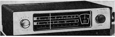
Fig. 12.6. The Allied Model KNllO AM, FM tuner.
The high-frequency oscillator, V6A, is a tuned-grid circuit employing inductive feedback between the plate and the grid. The oscillating voltage developed across Lr, is brought by a 1-mmf capacitor to the grid of V 2- The incoming signal and the oscillator signal mix in V2, and a 10.7 -mhz I.F. is developed across the primary winding of T1.
At the frequency at which FM oscillators function, any slight tendency to drift would tend to distort the sound output of the receiver and require frequent returning of the front dial. This can be minimized by shunting an automatic frequency control circuit across the oscillator. The purpose of this auxiliary circuit is to maintain the oscillator frequency constant at whatever position it is set by the tuning control. This is achieved by having the A.F.C. tube function as a reactance tube. The circuit is so connected that V3B appears to V 3A as a small variable capacitor. While the functioning of reactance tubes is discussed in detail in Section 14, it is not too difficult to see how V 3n can appear as a variable capacitor to L4. The oscillator and A.F.C. circuit of Fig. 12.5 is shown separately in Fig. 12.7. Note how the plate of V 3n is coupled to L4 by the 22-mmf capacitor. This not only brings the oscillator voltage directly to the plate of V aB, but it also means that any change in R.F. current flowing through V 3B will be coupled to L4. This latter point is important.
The same L4 voltage is also brought to the control grid circuit of V 3n by capacitor 0 12 and resistor R8 , causing a current to flow through these components. The capacitative reactance of C12 is several times greater than the resistance of R1, so that the current through R8C12 will lead the applied voltage by essentially 90°. The voltage developed across Rs by the current will be in phase with the current, and it is this voltage which acts as the grid signal. Hence, the grid signal will lead the R.F. voltage from L4 by 90°.
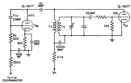
FIG. 12.7. Simplified diagram of the A.F.C. and R.F. oscillator stages
of the receiver shown in Fig. 12.5.
Next, let us consider the plate current of V3B. It is governed by the grid voltage and is in step with this grid signal. Thus, the plate current of V 3n leads the voltage across L4 by 90°. Since this R.F. plate current flows through L 4, V aB will appear as a capacitor shunting L4. This is so, because, in any capacitor connected across L4 , the voltage and current relationships just described would be present. The value of this capacitor is governed by the amount of plate current flowing which, in turn, depends upon the grid bias of V3B. This voltage is obtained from the output of the discriminator.
When a station is properly tuned in, the average d-c voltage across the discriminator load resistors is zero. However, if the station drifts to one side or the other, a negative or positive voltage will develop. This voltage, properly filtered to remove the audio variations, is fed to the grid of the A.F.C. tube where it will vary the plate current. This will have the same effect as varying the value of the capacitance which the reactance tube (Van) shunts across the oscillator circuit. Thus, if the oscillator tends to increase its frequency, the capacitance presented by V aB will increase, causing the frequency of the oscillator to drop. By the same token, if the oscillator frequency decreases, the A.F.C. capacitance will similarly decrease and offset the change in oscillator frequency.
Sometimes V3B is shown with no capacitance bridged from plate to grid as C1 in Fig. 12.7. In such instances, the internal capacitance between plate and grid of the tube is being used to bring the RF. voltage to the grid circuit.
Beyond the FM mixer, the 10.7 -mhz I.F. signal is amplified by V6 and V1, then further amplified and limited by V 8 and V 0. The latter two tubes operate with grid leak bias and low plate and screen voltages, thereby effecting signal saturation by two methods. Next, the signal is applied to the 6AL5 discriminator (V10) where the audio variations are re-obtained.
The signal is then brought to terminal 3, section 1, of switch S1 (labeled S1.1 in Fig. 12.5). From here, with the switch in the proper position, it is transferred to the grid of the cathode follower. The output from this stage is obtained from the cathode circuit.
Switch S1 is a five-position switch with the following positions: OFF; AM; FM-AFC; FM, and TV. In the OFF position, the power is completely removed from the receiver. In the AM position, the AM stages are activated and those stages which operate solely on FM have their B+ voltage removed. In the third position, FM-AFC, the FM section of the receiver is in operation and the A.F.C. stage is functioning. For the fourth position, FM, the entire FM section is functioning as in the previous switch position, but the A.F.C. circuit is inactivated. This is done to permit the tuning in of weak signals; when these signals are properly brought in, the A.F.C. control can be re-established. Without this cutout, the stronger stations would tend to dominate, and any weak signal near a strong signal would be obscured. In the final position, TV, the filaments to the various tubes are powered, but all of the B+ is removed. This position is made available should this unit be used in conjunction with a TV receiver. By keeping the filaments lit, the user can always bring in the AM or FM sections of this receiver whenever he desires simply by rotating switch S1. Switch S1 has 7 sections. That is, it possesses 7 separate sections, all mechanically mounted on the same actuating shaft. This means that all sections are in position 1 at the same time, or position 2 at the same time, etc. Each section is electrically independent of all the others and each deals with a different segment of the circuit. Section 1 (labeled S1.1 in Fig. 12.5) is concerned with bringing the proper audio voltage to the cathode follower, V 1m. Section 2 (S1-2) provides B+ voltage to the FM, R.F. amplifier, FM mixer, FM oscillator and A.F.C. tube when the FM section of the system is in operation. Section 3 (81.8) inactivates the FM, A.F.C. line when this is desired. Section 4 (81.4) grounds the A.V.C. line when the AM section of the receiver is not in use. Section 5 (S1-5 ) brings B+ voltage to V 1 when the set is operating on F-:M. It removes this voltage from the tube when the receiver is set for AM. For the latter condition, the tube functions as a diode to detect the AM signal. Section 6 (S1-6 ) lights the appropriate pilot bulb for the service desired from the receiver. Finally, section 7 (S1-7) serves as the power on-off switch for the entire receiver.
It is suggested that the reader become fully acquainted with these switch sections because they are so vital to every portion of the receiver. Without them, the receiver front panel would be hopelessly filled with switches.
The meter amplifier, V 11A, functions whenever an audio signal is fed to the cathode follower. This amplifier uses the d-c voltage output of the FM discriminator to establish the reading of the meter. The latter is connected between the cathode of the tube and R1. The meter is adjusted initially so that it reads mid-scale when no signal is received. For FM reception, the d-c voltage developed at the output of the discriminator is zero when a station is properly tuned in. Therefore, the meter amplifier will receive a zero d-c voltage and the meter needle will remain stationed at mid-scale.
If the receiver is tuned to one side of the station, the voltage from the discriminator will assume a negative or positive polarity. This will cause the meter needle to swing away from center. If the receiver is tuned in the opposite direction, the polarity of the d-c voltage at the discriminator output will likewise reverse and the meter needle will swing in the opposite direction. Proper tuning is indicated when the meter needle is precisely at the central point. This is the best type of FM tuning indicator since it reveals when the station is properly centered in the band pass of the tuned circuit of the receiver. Resistors R2 and Rs and capacitor C1 serve to filter the signal received from the discriminator, removing the audio variations and permitting only the d-c voltage from the latter stage to reach V11A. Resistors R4 and R5 and capacitors C2 and Cs perform the same function for the voltage which is applied to the grid of the A.F.C. tube, V aB. Here, too, only the average d-c output voltage of the Foster-Seeley discriminator is desired.
AM Section. The AM section consists of a separate 6CB6 R.F. amplifier (V4 ), a separate 6BE6 AM converter (V5), one I.F. stage (V6 ), and an AM detector (V7). After this, the signal is applied through section 1 of S1 to the input of the cathode follower. In detail, the antenna for the AM, R.F. amplifier is a ferrite rod, L6. Its signal is fed to V4, amplified and then transferred to V Ii. Here the signal is combined with a locally generated oscillator voltage and the resultant 455- khz I.F. voltage is developed across the primary of T6. The signal is then inductively coupled to the secondary and applied to the control grid of the first I.F. amplifier, V6.
The next stage, V7, functions as an AM diode detector because, during AM operation of the receiver, the screen grid and plate elements are not given any B+ voltage. The load resistor for the detector is R6 while c_., C5, C6, and R7 serve as R.F. filters. The audio output developed across R6 is transferred to section 1 of switch S1, and when this switch is turned to the AM position, the signal is brought both to the meter amplifier and the cathode follower. At the same time, the d-c voltage developed across R6 is employed as an A.V.C. voltage and is used to regulate the gain of V6, V5, and V4. Thus, the first three stages of this AM section are subject to A.V.C. control. This is somewhat more extensive than is normally employed.
The d-c voltage which the meter amplifier receives is derived from the A.V.C. line; therefore, it possesses a negative polarity. When no station is received, the d-c voltage at the grid of V 11A is zero, and the meter needle is in the center of the range. When a signal is received, a negative voltage will develop, this voltage reaching its highest value when the station is properly tuned in. Therefore, for AM reception, optimum setting of the tuning control is indicated when the meter needle is as far to the right as it will go. Note that this differs from the meter performance during FM reception.
=============
-----
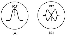
TABLE I. ALIGNMENT PROCEDURE FOR AM-FM TUNER of Fig. 12.5. (Courtesy H.W. Sams & Co.)
Initial steps.
Volume control should be at maximum position. Output of signal generator should be no higher than necessary to obtain an output reading. Use an insulated alignment screwdriver for adjusting.
FM I.F. ALIGNMENT USING FM SIGNAL GENERATOR AND OSCILLOSCOPE
FM R.F. ALIGNMENT
=====================
Power for all sections of the receiver is provided by a 6X4 full-wave rectifier. Voltages of 120 and 160 volts are available. As is common practice, B+ voltage is applied only to those sections of the receiver in use for a specific setting of the selector switch. All other portions of the receiver have their B+ removed. This is done to avoid interference which would certainly arise if all sections received B+ at the same time.
Note the absence of any volume control on the front panel of the receiver. Actually, the output obtained from the cathode follower can be regulated, but this is done not by a front panel control but by a rear panel screwdriver control. It is generally adjusted once and then left at this position. Further volume regulation would be made by a suitable front panel control in the audio power amplifier receiving the tuner signal.
One additional feature of this receiver is a 10-khz filter inserted between the output of the AM detector and the cathode follower. The components of this filter, C1 and L1, are designed to remove the 10-khz whistle which frequently develops when AM stations are close enough to beat with each other. The beating or mixing of the two signals occurs in the AM detector, and the resultant 10- khz note then passes through the audio system and is heard in the loudspeaker. To adjust L 7 and C7, several methods are avail able. When the AM section of the receiver is aligned, the 455- khz I.F. signal can be modulated with a 10- khz note instead of the normal 400-hz note.
While most audio signal generators only provide 400-hz modulation, nearly all have provision for external modulation. A suitable 10-khz signal can be obtained from an audio oscillator for this purpose.
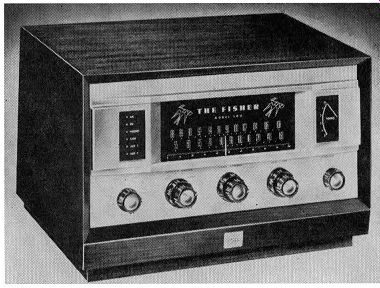
Fig. 12.8. The Fisher Model 500 AM, FM receiver (Courtesy Fisher Radio
Corp.).
Another approach is simply to apply the 10-khz signal from an audio oscillator at the junction of R1 and C4. The 10-khz note will then be heard in the loudspeaker, and C7 can be adjusted for minimum sound.
Receiver Alignment. The alignment procedure for this receiver is given in chart form in Table I. Included are instructions for a visual alignment of the I.F. section and the discriminator.
An Extensive AM, FM Receiver. The receiver shown in Fig. 12.8 employs 14 tubes not only to provide reception of AM and FM signals and reproduce them on an output loudspeaker, but also to enable records and audio inputs from other sources to play through the same audio system.
Thus, we have combined on one chassis a complete AM receiver, a complete FM receiver, and a phonograph playback system. (See Fig. 12.9.) The only additional equipment required with this unit, a Fisher Model 500 receiver, are a record changer and a suitable record cartridge.
FM Receiver Section. Most of the system is similar to the FM sections of previously described receivers. However, there are several circuits which warrant special attention. In the R.F. amplifier, the two triode sections of the 6BC8 form a cascode arrangement. The first section, Vu, is connected as a conventional grounded cathode amplifier, with the incoming signal received at the control grid and the output signal developed in the plate circuit. This signal is then transferred by C10 to the cathode of the second triode, V1B. The grid of this section is placed at R.F. ground potential by C12; thus, this section is operating as a grounded-grid amplifier.
Output from V1B is also obtained from its plate circuit and fed by C14 to the grid of mixer, V 2A· Both control grids of V1A and V1B have applied to them a negative control voltage obtained from resistor R38 in the ratio detector. This resistor has developed across it a negative voltage whose amplitude is a measure of the strength of the incoming signal. This voltage, properly filtered to remove any audio signal, is employed as an A.V.C. voltage for FM reception.
The pentode section of a 6U8 serves as the FM mixer, the triode section of this tube provides the necessary oscillator voltage. The tube is constructed so that each section is electrically independent of the other and an external 2.2-mmf capacitor must be connected between the two control grids in order to bring the oscillator signal to the mixer. No FM A.F.C. circuit is used here, the oscillator tuning circuit relying on two temperature compensating capacitors, C23 and C21 , to furnish the necessary frequency stabilization. These capacitors have a negative temperature characteristic, so that, as the circuit warms up, the capacitance value of each unit de creases. This counterbalances the decrease in frequency which the same warm-up produces in the tuning and trimmer capacitors and in the coils of these resonant circuits.
For FM signals, there are two I.F. amplifiers and one limiter before the signal reaches the balanced ratio detector. In place of vacuum-tube diodes, the ratio detector employs two matched germanium diodes. Additional balancing is achieved by resistors R37 and R41. The audio signal developed by this stage is transferred to switch S1, section 5 through a de emphasis circuit R36 and C48 . The connection at this switch is made at terminal 2. This switch, which has nine different positions, is shown in position 1. This is the AM position, for the reception of AM signals. The remaining positions are:
2 - FM
3 -AES
4 - RIAA
5 - LP
6- NAB
7 - TAPE
8-AUX #1
9 - AUX #2
Positions 3, 4, 5, and 6 refer to record equalization, while 7, 8, and 9 enable other audio signals, obtained from auxiliary equipment (including a tape recorder), to be passed through the audio system. A "Phono" input, also available, is active during the four equalization positions.
We might digress here for a moment and examine the notation employed for the selector switch. In a previous receiver, Fig. 12.6, one way of illustrating complex selector switches was demonstrated. There, the various terminals of each section were shown in numbered sequence and the terminal to which contact was being made was indicated by the position of a central arm with an arrowhead at one end. While this demonstrated the action of the switch quite clearly, it did not depict the switch as it is physically, and anyone not familiar with these units could easily be lead astray when forced to work between the schematic diagram and the actual receiver.
A more accurate representation of the selector switch is rendered by the notation employed in Fig. 12.9. Each section of the switch is identified by a different number and, if there are front and rear plates on the section, they are also shown.
Each section of the switch contains a movable, circular metallic strip which, as it rotates, contacts certain switch terminals. Some terminals are blank, indicating that no connection is made to them. Where a connection does exist, a small arrow ( denoting a contact arm) extends from the terminal in toward the movable contacting plate. If the arrow does not touch the plate, then no contact is made between the two. However, in some position of the switch, contact will occur.
Some arrows are longer than others and these generally remain in contact with the movable plate (as it is rotated) longer than the shorter arrows.
If the plate forms a full ring, then the longer arrow will contact the ring in every position of the switch. At other times, the contact will exist for several switch positions and be broken for other positions.
Three pieces of information are usually given concerning a selector switch. First, its present position is indicated. In Fig. 12.9, switch S1 is in the AM position. Second, the other positions are also designated as to function. Finally, the direction in which each section is to turn from its present position, in order to follow the sequency, is indicated, too. This is done in Fig. 12.9. Note that the front plate of a section will turn in one direction, while the rear plate will turn in the opposite direction.
Let us examine some of the sections of switch S1 to illustrate some of the foregoing points. In section 5, front, the arrow from terminal No. 10 extends far enough out to contact the movable plate in all positions of the switch. The wire from terminal No. 10 goes to the grid of the first A.F. amplifier, and all signals pass through this section of the circuit. In the position shown, the movable plate is touching the arrow extending inward from terminal No. 1. Thus, the signal at terminal No. 1 makes electrical contact with terminal No. 10 and this brings the output from the AM detector to Vo, In the next position of the switch, the plate is moved one position clock wise. Contact now is no longer made to terminal No. 1, but to terminal No. 2. While this terminal has an arrowhead, it does not show any wire coming to it from the circuit. Thus, is would appear as if, in the FM position of the switch, nothing from the FM section of the receiver will reach V0. However, if you examine section 5, rear, of switch S1 (near the FM detector), you will note that the output of the ratio detector does reach terminal No. 2. Since the section has only one set of terminals, the connection at terminal No. 2 of section 5, rear, is the same as a connection at terminal No. 2 of section 5, front. (Most of the time, the front plate contacts terminals that the rear plate does not, and vice versa. Occasionally, both plates will have terminals in common, such as No. 2 here.) Note, too, that section 5 is so set up that those contacts not in use are grounded by the rear plate. This is useful in preventing any signal leakage into the active channel from an unused circuit.
Some of the sections have a large number of contacts, whereas some have very few. Section 2, front, has only three terminals to which wires go. Remember, too, that there is no direct electrical contact between the front and rear movable plates of a section. Any contact that may exist (and this is not done too often) is achieved through a terminal that both plates are contacting at the same time. No section 3 of switch S1 will be found in Fig. 12.9. Such a section is physically present in the receiver, but it serves simply to provide tie points for some of the components in the switch circuitry.
To return to the circuit analysis, the output of the ratio detector is applied to V 9A through the selector switch when the latter is in the FM position. This stage is an audio voltage amplifier, with a small amount of negative feedback developed by R56 , the 3.3-megohm resistor connected between plate and grid. The combination of C61 and R54 just in front of R56 is designed to improve the high-frequency response of the stage. It does this by permitting the higher audio frequencies to reach the grid of V9A with less attenuation than lower audio signals. The latter are faced with a higher impedance from C61 and R54. The output of V 9A is transferred to the volume control. In addition to its normal function of varying the volume of the output audio sound, this control also has associated with it a four-position "Loudness" switch, S2, The purpose of the "Loudness" control stems from the way the human ear responds to tones of different frequencies. This was previously discussed in connection with Fig. 10.1 where it was noted that the overall ear response becomes flatter as the volume increases. When the volume is turned down, the ear hears less of the high and low audio frequencies. If we listened to this music as it was being played by an orchestra, the sound level would be high and both high and low audio frequencies would be heard as well as the medium frequencies. However, when the selection is played back at a much lower level (simply because most home playback systems are not capable of the sound intensity of the original), the low and high audio frequencies suffer a proportionately greater loss due to the aforementioned characteristics of our ears. It is the purpose of the loudness control to compensate for this loss by increasing the amplitude of the high and low audio frequencies.
Note that, since the ear becomes less sensitive to bass frequencies than to high frequencies as the volume decreases, greater boost is given the bass frequencies by these loudness controls. Sometimes high-frequency compensation is ignored completely because it is felt that the additional boost does not warrant the expense required to achieve it.
The loudness control is set according to the level of the sound. If a high level of sound is desired, less loudness correction is required; if the sound is normally kept now, a greater amount of correction is added.
Some readers may wonder why a special loudness control is needed since the base and treble controls can provide the same emphasis to the two ends of the audio frequency range. First, the loudness control is designed ac cording to the frequency and loudness characteristics of the ears, as revealed by the curves of Fig. 10.1. Thus, the control introduces a fixed amount of compensation at each position.
Second, if we employed the normal bass and treble controls to compensate for the loss in hearing, we would not have enough additional leeway in these controls to permit adjustment for the individual tastes of the listener.
Because of this, two sets of controls are provided.
Following the volume control, there are separate bass and treble controls of the continuous variety. These function in the same way as the controls discussed in Section 10. The bass control provides a boost of 17 db when tuned fully clockwise and a reduction of 15 db when tuned fully counter-clockwise. The treble control has approximately the same range.
V 9A, V 9B and V 10A are single-ended audio voltage amplifiers. V10B is a split-load phase inverter, feeding equal and oppositely phased signals to the push-pull output stage. Beam power tetrodes are employed here. The signal is then transferred to an output transformer with secondary impedances of 4, 8, and 16 ohms. The amplifier is rated at 30 volts with a uniform frequency response from 16 to 32,000 cycles.
A small amount of negative feedback is provided from the secondary of T2 to the cathode of V IOA. In addition, C72 and C71 provide special high frequency feedback to offset a shift in phase that occurs for these frequencies in transformer T2. (It will be noted that the phase of the high frequencies fed back to the grid of the phase inverter is the same as the phase of the signals reaching this point through the other feedback path.
This is true because the signal fed back through R70 is applied to the cathode of V1BA and not its grid.) AM Section. The AM section of the circuit is straightforward, employing an R.F. amplifier, V3 , a converter, V4, one I.F. stage, F5 , which is shared with FM, and a detector, V6 . The latter tube, although a pentode, functions as a diode on AM because section 2 of switch S1 removes its plate and screen-grid voltages at this time. The AM detector load resistor is R25 and, from this point, audio and negative A.V.C. voltages are obtained.
The audio signal is fed to the grid of V 9A through section 5, front, of switch 1, while the A.V.C. voltage is brought to section 2, rear, switch S1 by resistor R26. The switch, in the AM position, transfers this A.V.C. voltage to the control grid of V3. A.V.C. voltage is also applied to V4 and V5 , al though this is done directly, without any switches.
A tuning meter is employed in conjunction with the AM section. One side of this meter is connected to the screen grid and plate of the AM R.F. amplifier. The other side of the meter is connected to 135 volts through a resistive voltage-dividing network, R32 and R33. Thus, this side of the meter receives a fixed voltage.
The voltage drop across R15 (in the screen grid and plate circuit of V3) will vary with the strength of the signal passing through V3. This is because the gain (and, consequently, the current) of V 3 is controlled by the A.V.C. voltage.
A variable resistor in the cathode leg of V3 permits adjustment of the needle swing so that the needle does not go off scale with the strongest received signal.
Interestingly enough, the same tuning meter also serves as a tuning indicator on FM. When the selector switch is turned to the FM position, section 2, rear, of 81 feeds the negative d-c voltage developed by C5 (of the ratio detector) to the control grid of V3. This voltage will regulate the amount of current flowing through V3 and, consequently, the voltage present at its screen grid. Thus, even though V3 amplifies only AM signals-and, hence, operates only when the set is turned to AM-it serves as d-c amplifier on FM for the tuning meter. In recognition of this latter function, V3, al ways has its plate and screen grid voltages, whereas these are removed from V4 in the FM position of S1.
-----------

TABLE II. ALIGNMENT PROCEDURE FOR THE AM, FM RECEIVER OF Fro. 12.8. (Courtesy H. W. Sams & Co., Inc.) Pre-alignment instructions Volume control should be at maximum position. Output of signal generator should be no higher than necessary to obtain an output reading. Use an insulated alignment screwdriver for adjusting.
---------
FM I.F. ALIGNMENT USING FM SIGNAL GENERATOR AND OSCILLOSCOPE
-------- FM R.F. ALIGNMENT
Preamplifier. The phono preamplifier employs a single 12AX7, V8.
This added amplification is provided for magnetic cartridges only, since the output of a crystal cartridge would overload the audio system with this additional pre-amplification. The signal from the cartridge is passed through the two amplifiers and an equalizing circuit before it is transferred by section 5, front, of switch 1 to V9A. Four types of equalization are provided: AES, RIAA, LP, and NAB. This is the conventional line-up, although frequently a fifth network entitled "Foreign" is incorporated also.
The 12AX7 tube, as we have already noted in Section 10, is specifically designed for low-level audio amplification, having low-noise and low-hum characteristics. In the present circuit, interference from the latter source is avoided completely by powering the filament of V8 (and Vo and V10 as well) with d-c. This voltage is obtained from the power supply.
Power Supply. Two separate full-wave rectifiers in the power supply develop four different positive voltages ( 420, 340, 140, and 135 volts) and one negative voltage (-36 volts). The latter potential is produced by having all of the circuit current pass through R85. Its purpose is to heat the filaments of the three 12AX7 tubes, V8, V9 , and V10. Extensive filtering is employed in both full-wave circuits. It is particularly important in a high-fidelity system to keep the level of ac hum far below the lowest usable level of the audio signal.
The front part of section 1, switch S1, brings in a different pilot bulb for each different function of the receiver. Thus, there is one bulb for the AM position, one for FM, one bulb when the phonograph is being played, and one bulb each for the positions of tape, auxiliary input No. 1, and auxiliary input No. 2. These bulbs are physically positioned one above the other behind the front panel and serve to remind the set user of the position in which the receiver is set.
The complete alignment procedure for this receiver is given in Table II. The various steps are straightforward and follow the general alignment sequence previously given. Adjustments are labeled by the capital letter A and extend from A1 to A23.
In the FM I.F. alignment instructions, the table indicates that the output of the signal generator is connected to the ungrounded tube shield on V2 (6U8). To unground this shield, it is lifted and then made to rest on the glass envelope of the tube in such a way that no contact with the bottom grounded sleeve occurs. In this position, the shield is floating and when it receives the generator signal, it capacitatively couples this to the tube elements through the glass envelope. This is a simple way to inject the signal into a circuit and it works exceptionally well.
EXAM
1. In what respects is an AM-FM tuner different from a complete AM-FM receiver?
2. Which stages in Fig. 12.2 serve both AM and FM signals? Which stages serve one signal only? For the latter question, indicate which signal.
3. If resistor R11 in Fig. 12.2 opened up, what effect would this have on receiver operation?
4. What test instruments are needed to align the receiver in Fig. 12.1?
5. How are the FM R.F. tuning circuits adjusted in Fig. 12.2?
6. Describe in detail the operation of the R.F. amplifier in Fig. 12.4.
7. What features exist in the Heath FM tuner that are not found in the Granco receiver?
8. Describe the complete alignment procedure for the Heath tuner.
9. What purpose is served by the following components in Fig. 12.4: R2 , C 3 ; R3 ; R4, C4 ; R5.
10. What stages in Fig. 12.4 are controlled by the A.V.C. voltage? Where is the A.V.C. voltage obtained?
11. How is FM receiver sensitivity usually stated? Explain the meaning of this notation.
12. Draw a block diagram of the tuner shown in Fig. 12.5.
13. What is the purpose of the A.F.C. stage in Fig. 12.5? Where does this stage obtain its regulating voltage? Trace out the path.
14. Explain how the tuning meter in Fig. 12.5 operates on AM and FM.
15. Indicate the function served by each section of selector switch S1 in Fig. 12.5.
16. Describe the FM alignment procedure for the tuner in Fig. 12.5.
17. What is the purpose of C7, L7 in Fig. 12.5? How does it achieve this?
18. Describe the operation of the FM detector used in Fig. 12.5.
19. What form of A.V.C. is employed in the AM section? FM section?
20. Identify all of the R.F. and I.F. tuning circuits associated with the FM section of the receiver in Fig. 12.5.
21. What can the receiver in Fig. 12.8 do that none of the tuners could? What stages enable it to do these additional functions?
22. Identify the loudness control circuitry in Fig. 12.8. What purpose does this control serve?
23. Explain how the treble and bass controls operate in the receiver of Fig. 12.8.
24. Where is the record equalizing network found in the circuit of Fig. 12.8? Identify the components of this network.
25. Identify the following, using Fig. 12.8.
(a) The section of switch S1 which determines whether B+ is applied to the FM section or the AM section.
(b) The components of the de-emphasis network at the output of the FM detector.
(c) All of the circuit components of the AM local oscillator.
(d) Every tube in the receiver which has audio current flowing through it.
(e) The stabilizing components in the FM detector.
26. Indicate how you would visually align the FM I.F. and detector stages in Fig.12.8.
+++++++++++