Introduction. In conventional sound broadcast receivers, it is current practice to tune the set by means of variable air capacitors or by changing the position of iron cores within certain inductances. These units are ganged together, enabling the use of one dial to tune several stages simultaneously.
At the standard broadcast frequencies, 550 to 1700 khz, and even at the higher short-wave frequencies, the coils and capacitors used are quite substantial in appearance. As we increase the operating frequency of the receiver, however, the units decrease in size until, at the FM band, 88 to 108 mhz, the coils contain fewer than 10 turns and the capacitors have 3 or 4 small plates. Furthermore, extreme care must be taken in parts placement and in circuit wiring. Consider the latter, for example. Any length of wire, regardless of shape, contains a certain amount of inductance. This inductance is present at the lower frequencies just as concretely as it is at the higher frequencies.
That it is important in one instance and not the other is merely due to its relationship to the rest of the circuit, particularly the tuning networks. At the low frequencies, the inductance introduced by the wiring is negligible when compared to the tuning coil's actual inductance. Hence, it may be (and is) disregarded. At the higher frequencies, however, this same inductance of the wiring forms a significant percentage of the tuned-circuit inductance and, as such, cannot be ignored. It is here that the difficulty arises.
Not only must the connections be made as short as possible, but we find that there is considerable inductance present in the capacitor structure itself.
Microphonic howls and inductive coupling between the various sections of the capacitor structure (and hence between the stages controlled by these sections) are two of the undesirable results that occur.
In present-day FM receivers, tuning by means of suitable variable capacitors and fixed inductances is still widely used and, when properly constructed, will yield good results. In addition, there has been developed a whole new group of tuners which are designed to meet the altered conditions imposed by the higher frequencies with greater efficiency and more gain. It is the purpose of this Section to investigate these newer types of tuners so that the serviceman, when working with FM receivers, will be able to service them intelligently. We are entering an era where service ability is more closely linked to circuit understanding than it has been previously.
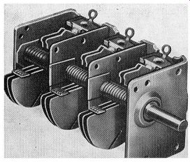
FIG. 5.1. A 3-gang variable capacitor employed in FM receivers.
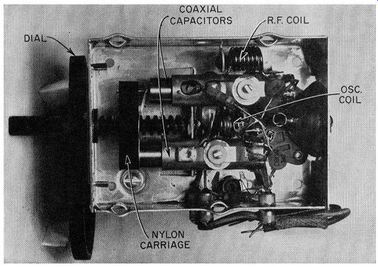
FIG. 5.2. A 2-section coaxially-constructed tuning capacitor. (Courtesy
Granco)
Coaxial Tuning Capacitor. Variable capacitors can take several forms, the most common of which is shown in Fig. 5.1. However, one FM receiver manufacturer has developed a variable capacitor possessing a coaxial-type construction. (See Fig. 5.2.) One plate of the capacitor is formed by an outer cylinder which is heat shrunk onto a glass cylinder.
This glass serves as the dielectric of the unit. The other plate of the capacitor is a movable cylinder whose diameter is slightly less than that of the glass cylinder. This enables it to be moved back and forth by a nylon lead screw to which it is attached.
One such capacitor is employed in the radio-frequency (R.F.) amplifier tuning circuit and another in the oscillator tuning circuit. Both capacitors are mechanically ganged together by a nylon carriage so that they can be varied in step across the FM band.
Each variable tuning unit has a small compression-type variable trimmer placed across the gap formed by the two metal cylinder sections. This permits the circuit to be aligned at the high-frequency end of the band to achieve the proper tracking.
Permeability Tuning. There are several methods by which the inductance of the coils can be varied in order to tune the receiver. We can use brass or copper slugs or a powdered-iron, permeability-tuning element. A comparison between the slugs and the permeability clement indicates that the inductance change, for a definite decrease in Q, is greater with the iron core than with the slug. Furthermore, a coil tuned with a slug possesses a wider bandwidth than one which has an iron core. The reason for this is due to the eddy current loss within the slug, which acts as a shorted turn.
Q of a tuning circuit is a measure of the sharpness of the response curve of that circuit. A tuned circuit whose Q is high will have a sharper (i.e., narrower) tuning curve than a circuit whose Q value is low. Thus, the selectivity of a high-Q circuit will be better. Also, high-Q tuning circuits provide a greater signal output (over the tuning band) than low-Q circuits, for the same received signal.
In most tuning circuits possessing coils and capacitors, Q is effectively wL governed by the coil. Hence, Q is given as R' where w = 2rf.
In the design of a high-frequency permeability tuner, cognizance must be taken of the stray or circuit capacitance which is present across the coil.
With careful design, the lowest value of the capacitance is close to 15 mmf.
The small value, in conjunction with the relatively high value of inductance, presents a high L/C ratio. Since gain is directly proportional to the impedance presented by the resonant circuit and this, in turn, is governed by the L/C ratio of the network, we find that a high gain is available with the fore going arrangement. However, when this is put to practical use in the receiver, it will be found that the R.F. selectivity is poor. The result, as shown in Section 7, is a large number of spurious responses.
The reason for poor R.F. selectivity at high frequencies is due to the damping or shunting effect of the R.F. tube input. A nominal value for the tube input loading at 100 mhz is approximately 3500 ohms. This impedance is across the permeability-tuned coil and the stray 15-mmf shunting capacitance. At resonance, the impedance of the tuned circuit is given by:
Where … Q = the Q of the coil
C = 15mmf Q roC (14)
The coil Q is determined by the dimensions of the coil and is approximately 90. At 100 mhz, the value of the foregoing expression, after substituting the figures listed, is 10,000 ohms. Since the tube shunts the tuned circuit, the total impedance of the two is 2600 ohms. Practically, then, the impedance of the tuned circuit, which is what the incoming signal "sees," is 2600 ohms. Hence, we can set Q - = 2600 ohms roC
Since "' and C have not changed, the lowered value (from 10,000 to 2600 ohms) must be due to the lowering of the effective Q of the network. Solving, we obtain an effective value of 23 for Q.
Now, let us increase the total capacitance from 15 mmf to 30 mmf by the addition of more capacitance. The Q of the coil remains approximately at 90 in spite of a decrease in the number of turns due to the added capacitance. Solving for Q/roC now, we obtain a value of 5000 ohms. This value, in parallel with the tube (3500 ohms), produces a total input impedance of 2100 ohms. The effect on the overall Q is to bring it to an effective value of 38. Thus, although raising the shunt capacitance decreased the impedance (from 2600 to 2100 ohms), it did raise the effective Q of the circuit, in this instance by 65 percent. The result is a slight loss in gain but a substantial increase in selectivity. Hence, in the receiver, a small capacitance is shunted across each coil.
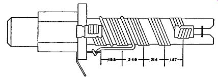
Fig. 5.3. A four-wire permeability-tuned coil. The variable pitch produces
a linear characteristic.
In the particular permeability-tuned coils shown in Fig. 5.3, four-strand tinsel wire was used to retain wire flexibility in winding. The use of four parallel wires is due to the difficulty of obtaining the necessary inductance change with the small number of turns on the coil. It was just pointed out that, for better selectivity, the shunt capacitance is increased and the coil inductance is lowered. Hence, the ratio of inductance change for a certain core travel decreases, and the frequency band is not covered by a complete travel of the core within the distance allotted to it on the dial. To overcome this difficulty, the width of each turn is increased. As the wire width in creases, the tuning range is increased. A similar result may be had by winding the coil with parallel wires. This accounts for the four conductors shown in Fig. 5.3.
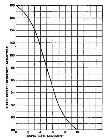
Fig. 5.4. The nonlinear shape of the tuning curve when the winding of
the permeability-tuned coil is uniform in pitch.
Coil Spacing: A serviceman, called upon to repair one of these coils, would be completely unable to return the set to its proper operating condition unless he wound the coils correctly. If the coils are closely inspected, it will be found that the winding is not uniform in pitch. Fig. 5.4 illustrates the shape of the tuning curve for a permeability unit if the winding is made uniform in pitch. The nonlinear slope at each end occurs because the incremental inductance variation is maximum when the leading edge of the core is in the center of the coil and minimum at the start or finish of the core travel.
To straighten out the curvature at the ends of the characteristic, the coil turns are bunched at the ends and spread out in the center. This increases the inductance variation (with core movement) at each end and decreases it in the middle. To insure further that an almost linear characteristic response is obtained, only part of the complete tuning curve is used. The coil and core lengths are made larger than necessary, and the core, over the band desired, is never out of the coil. The curve of Fig. 5.5 is the result.
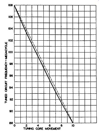
Fig. 5.5. The improved tuning curve (solid line) when the turn spacing
is made logarithmic. The dotted line, which is exactly linear, is used
for comparison.
In the mass production of permeability-tuned coils, it must be expected that a certain variation between units will occur. Since the R.F., mixer, and oscillator coils are tuned simultaneously by one mechanism, some method must be available which will permit a preliminary adjustment in order that all the coils track. The idea of using a variable trimmer capacitor is possible, but a variable capacitor is highly susceptible to change with temperature and would be highly detrimental to receiver stability. It was discovered, however, that, by means of a single adjustment of the initial core position with respect to the coil winding, it would be possible to compensate for small differences. Thus, when the coils are mounted and tested, any difference in tracking is compensated for by a single initial advancing or retarding of the iron core of each coil.
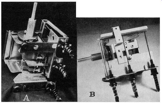
Fig. 5.6. (A) Receiver tuning assembly showing the mounting of the permeability
coils. (B) Underside view.
Photographs of the entire tuning assembly are shown in Fig. 5.6. The FM antenna, mixer, and oscillator coils are mounted on a bracket fastened to the side of a conventional variable capacitor. The latter is used, in this receiver, to tune the AM broadcast and short-wave bands. A cam is mounted on the shaft of the variable capacitor and operates a rocker arm which moves the iron tuning cores in the three high frequency coils. The unit is very compact, reducing all stray capacitance and inductance to a minimum.
The front-end section of an AM FM receiver employing permeability tuning is shown in Fig. 5.7. The dotted lines represent the mechanical coupling which exists between the cores of the FM tuning coils (L2 and L3 ) and the two variable capacitors in the AM section. One variable capacitor tunes the AM antenna coil (a rod antenna) ; the other tunes the AM oscillator coil, L_7.
In somewhat greater detail, the FM R.F. amplifier is connected with the signal applied to the cathode and the grid placed at ground potential.
This is known as a grounded-grid amplifier and it possesses several advantageous characteristics for high-frequency operation. This is discussed more fully on page 103.
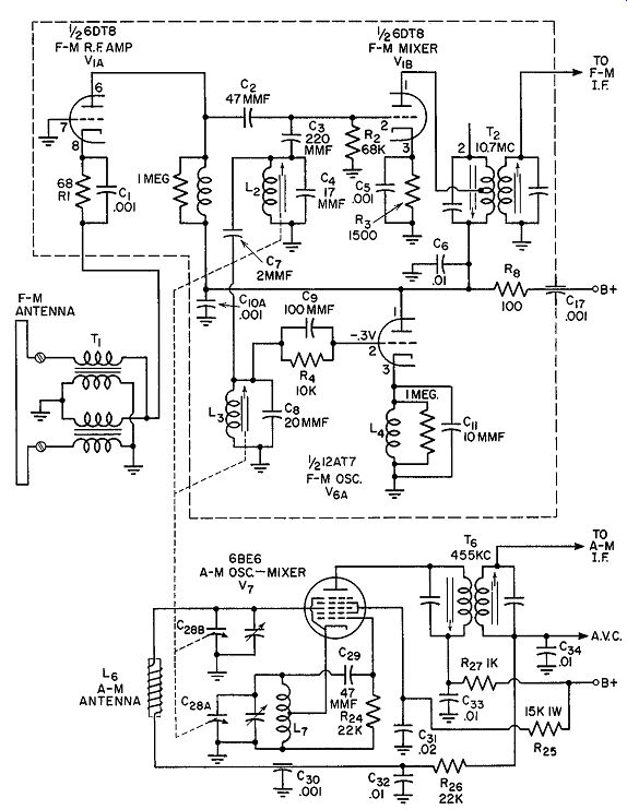
Fig. 5.7. The front-end stages of an AM, FM receiver employing inductance
tuning on the FM band.
The input circuit is untuned, possessing only a matching transformer to match the 300-ohm folded dipole, which is balanced, to the much lower un balanced impedance of the R.F. amplifier cathode. R1 establishes grid-to cathode bias for the tube; C1 bypasses the R.F. signal currents around R1.
The plate circuit of V1A contains an untuned coil which acts as a wide band load for the tube. The first signal tuning circuit, L2 and 0 4, is in the grid circuit of the mixer, V1B. L2 is permeability-tuned and it, in conjunction with 04, establishes the input frequency to be received. The mixer grid circuit also receives a portion of the oscillator voltage by way of C7. The two signals combine in V1B to produce the difference or I.F. signal (10.7 mhz). This is then coupled to the I.F. amplifiers.
The FM oscillator is of the ultraudion variety, with the internal capacitances of the tube playing a significant role in its operation. The tuning circuit, L3 and C8 , is essentially located between grid and plate. This can be seen by noting that the plate is at R.F. ground potential, placed there by C10A. However, since the plate and cathode cannot both be at the same R.F. potential (and still have the circuit function), a choke coil is placed in the cathode lead.
L3 is permeability-tuned. By mechanical coupling, its core moves in step with the core of L2 so that both circuits will track over the dial.
The AM section of the circuit uses a 6BE6 as a combination oscillator and mixer. The cathode, grid No. 1, and grids 2 and 4 (tied together internally) form the oscillator section of the converter. Grid No. 3 is the element to which the arriving signal is fed. The two voltages mix (by their effect on the same electron beam) and a difference frequency of 455 khz is produced.
This is then transferred to the I.F. system. (The sum of these two frequencies is also developed, as well as various harmonics, but none of these are accepted by the I.F. system.)
Coaxial Tuners. A variety of transmission line tuners have been employed for FM because of the high-Q values which they are able to develop. However, before we actually examine these units, let us briefly review the theory of transmission lines.
Transmission Lines: Every radio man is familiar with the conventional inductances, capacitances, and resistances, the types of which can be purchased in any radio shop. These units are said to be lumped because each is complete and distinct from the other.
Now, if two wires are mounted close together, using one to. conduct the current away from the source of voltage and the other to bring the current back, it would be found that the source of voltage "sees" not just two wires with some resistance in them, but rather a complex impedance which, when broken down, will reveal inductance and capacitance, too. The last two components are not visible upon a physical inspection of the wires, yet electrically they exist.
Of the two quantities, the presence of the capacitance can perhaps be more readily understood since, by definition, a capacitance is formed when ever two conductors are separated by a dielectric. In this instance the di electric is air, although it may be any nonconductor. Since the dielectric is never a perfect nonconductor, it is represented schematically by placing a large resistance across the condenser, this denoting leakage.
The presence of the inductive reactance is much more difficult to explain.
It is best to go back to the concept of magnetic lines of force and attack the problem from that angle. Inductance may be considered proportional to the number of magnetic lines of force per unit ampere that encircles a wire carrying the current. By starting with this idea, the inductance per unit length of any wire or system of wires can be developed.

Fig. 5.8. The electrical components of a transmission line.
To represent the foregoing inductance, capacitance, and resistance in schematic form for analytical purposes, a diagram such as shown in Fig. 5.8 is often used in engineering books on transmission lines. Although the various components are shown separate and distinct from each other, they are actually distributed evenly along the line. It is only because of our inability to show these components as they really are that we resort to this method.
Since the transmission line contains exactly the same three components as any ordinary resonant circuit, it is reasonable to expect that the same results can be obtained from these as from a resonant circuit. Hence, the length of the transmission line determines the frequency at which it will operate.
In common use today are three types of transmission lines: the twisted wire, the parallel-wire, and the coaxial transmission line. In the twisted-wire form, the two wires forming the line are twisted about each other, in the same manner as a lamp cord. In the next type, parallel-wire lines, the two wires are kept parallel and equidistant to each other, usually by means of spacers or by imbedding both wires in the dielectric material. The latter is true of the polyethylene transmission line used as lead-in cables for FM and television antennas. Finally, there is the coaxial cable, shown in Fig. 5.9, in which one conductor is placed inside and at the center of an outer conductor.

Fig. 5.9. A coaxial cable. D1 is the inside diameter of the outer conductor;
D2 is the outside diameter of the inside conductor.
Transmission Line Tuners. In choosing a transmission line, there were two factors to consider. First, the length of the line, in order to obtain the proper impedance at the operating frequencies, and, second, the best possible Q. It has been determined that the maximum impedance results when the outer to inner conductor ratio is 9.2 to 1. Actually, a 10 to 1 ratio is used with very little decrease in impedance. For this particular line the expressions governing the length of the line in order to give the required inductance and the Q are as follows:
L = 0.0117l microhenries
Q = 0.802D1 yF
where L = the inductance presented by the length of line used
l = length of the coaxial line
D1 = diameter of inner conductor
F = frequency at which the line is to be used
In common with conventional tuning circuits, one of the circuit components must be made variable in order that a definite range or band of frequencies be covered. It would be possible to resonate the inductance of the transmission line with a variable capacitor placed across the end of the line.
However, since the magnitude of the inductance is low, the use of a gang capacitor--one section for each transmission line tuner--would introduce too much additional inductance to prove useful. We can, however, resonate the inductance of the transmission line with a fixed capacitor, and then vary the inductance of the line by means of a powdered-iron core. In other words, we would have permeability-tuning, but in a form which is substantially different from the previous unit.
The coaxial line, with an iron core, is shown in Fig. 5.10. The iron core is mounted on a threaded rod and its position in the coaxial line is adjusted by turning the head or top of the threaded rod. The Q of the tuner, with the iron core, at 100 mhz is 335. The tube load reduces the effective Q of the circuit to 195 and this is approximately its final value, although the antenna loading lowers the Q somewhat. In the same diagram is the equivalent conventional circuit.
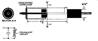
Fig. 5.10. The construction of the coaxial tuner. The equivalent coil
and capacitor is also shown.
An inexpensive, high-quality, concentric capacitor was developed for this particular unit. This is also shown in Fig. 5.10. The capacitor is of silver on mica construction. A highly desirable feature of the tuner is that the unit can be constructed as a mechanical assembly, without the necessity of electrical checking. With materials that are commercially available, the variation in inductance as calculated by the expressions previously given, is only ±0.5 percent. The coaxial line and capacitor type of construction forms a very compact unit. This reduces considerably the importance of the inductance present in leads connecting the tuned lines in the circuit. At 100 mhz, the problem of confining the desired signal pick-up to the antenna terminals of the receiver is quite difficult. Chassis pick-up, for example, tends to degrade the image and adjacent channel attenuation. However, when the entire unit is confined within the coaxial cable, the undesired pick-up be comes negligible. Removing the antenna, in the presence of a strong signal, completely kills the receiver output.
One application of the tuner to a superheterodyne AM FM receiver is shown in Fig. 5.11. The same tubes, V1 and V2, function for both AM and FM signals. However, by means of a two-position switch, different tuning circuits are brought in for AM and FM reception.
For FM operation, switch S1 is turned to the " FM" position. FM signals, entering the input terminals, encounter L2, the FM antenna coil. This is the initial coaxial line tuner. The signals accepted by L2 are applied to the control grid of V 1- Here they are amplified and then developed across L5, a small R.F. choke.
The second coaxial tuning network, Ls, obtains the signal from L5. L5 is connected to grid No. 3 of V2 , a 6BA7. This same tube also possesses an oscillator circuit between grid No. 1, the cathode, and grids 2 and 4. These two signals mix (through the electron stream) and develop a 10.7 -mhz difference frequency for the I.F. system. The FM oscillator coil is a third coaxial line, L4.
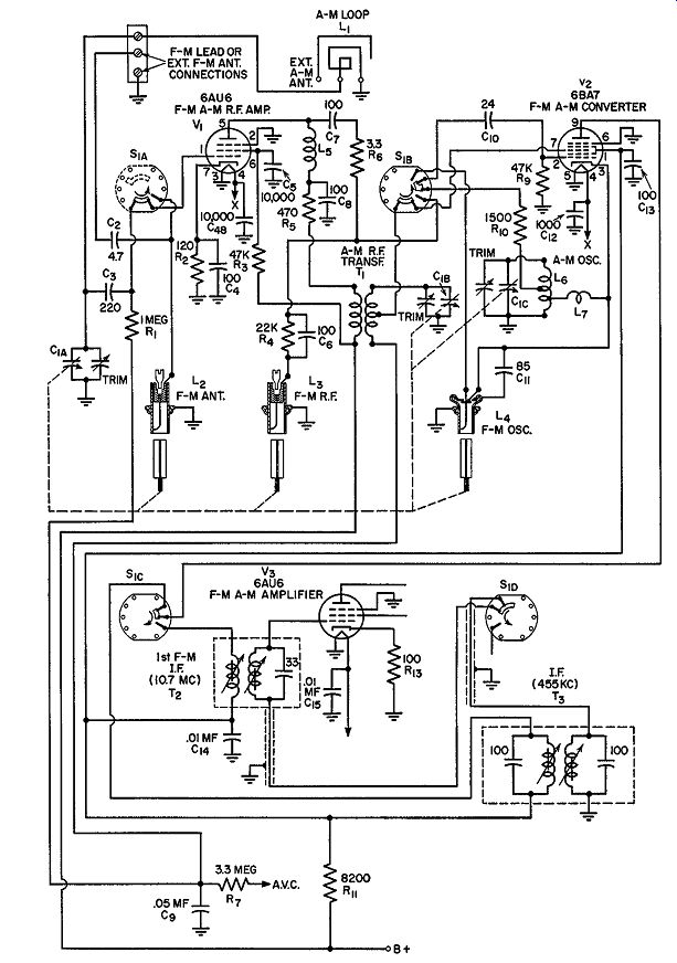
Fig. 5.11. The R.F. circuits of an AM, FM receiver using coaxial tuners
for FM reception. (Courtesy Motorola, Inc.)
Tuning across the FM band, 88 to 108 mhz, is achieved by mechanically coupling the iron core of each coaxial unit. The three units are adjusted to track so that each will possess the proper frequency at each point on the tuning dial.
For AM reception, switch S1 is turned to the " AM" position. The in coming signal is picked up by a small loop antenna and applied to grid No. 1 of V1. Tuning capacitor C1A tunes the loop. The AM output signal of V1 appears now across T1. L5 possesses too little inductance at the AM R.F. frequencies to have any noticeable effect. C8, a 100-mmf bypass capacitor, in conjunction with resistor R5, do tend to reduce the amplitude of the AM signal before it reaches T1. However, since the AM signal is initially quite strong and since it is further amplified by V1, this decrease is useful in pre venting V2 from overloading.
From T1, the AM signal is fed to grid No. 3 of V2 where it combines with a local oscillator signal developed by L6. Again, V 2 serves as a converter, producing a 455- khz I.F. signal which is transferred to the following I.F. system.
In the output circuit of V2, the third section of S1 (i.e., S10) brings in the desired I.F. transformer. When an FM signal is being received, T2 receives the 10.7 -mhz output of V2. When an AM signal is being received, transformer Ta is connected to the plate of V2.
The three AM tuning circuits (loop antenna, T1, and L6) are resonated to the proper frequency by a three-section variable capacitor. This unit is attached to the same mechanism employed to vary the iron core positions of L2, L3, and L4. In this way, only one tuning dial is needed for the entire receiver.
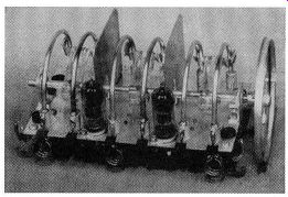
Fig. 5.12. A parallel resonant line tuning assembly. (Courtesy Approved
Electronic Instrument Corp.)
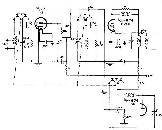
Fig. 5.13. Schematic diagram of the front-end section of an FM receiver
using parallel wire transmission line tuners.
Parallel-Wire Transmission Line Tuners. Another approach to trans mission line tuners, this time using parallel-wire lines, is shown in Fig. 5.12. The R.F. section consists of three sets of parallel-wire lines, each set having movable shorting bars which determine how much of the line is active. The shorting contacts are mounted on plastic bars and then attached to a common shaft. As the shaft is rotated counter-clockwise, the bars progressively short out more and more of the lines, raising their resonant frequency from 88 to 108 mhz.
(See Fig. 5.13.) To permit the three lines to track with each other, each line contains small end inductances and semi-fixed, temperature-compensated silver ceramic capacitors. At the high frequency end of the FM band, the series capacitors are adjusted for maximum output. At the low end of the FM band, 88 mhz, the end inductance coil turns are either spread apart or squeezed together to achieve tracking here. The whole unit is-rubber-mounted to give freedom from microphonics. Miniature tubes are used to provide excellent frequency stability and sensitivity. A 6AG5 is the R.F. amplifier, and a 6J6 double triode functions as a combination mixer-oscillator. Injection of the oscillator voltage into the mixer is accomplished with a 2-mmf coupling capacitor. The unit, mounted on the receiver chassis, is shown in Fig. 5.14.
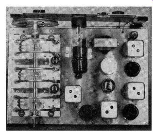
Fig. 5.14. The tuning assembly mounted on the receiver chassis. (Courtesy
Approved Electronic Instrument Corp.)
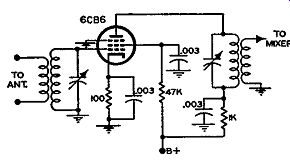
FIG. 5.15. Schematic diagram of an FM, R.F. amplifier.
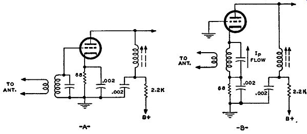
FIG. 5.16. (A) A conventional amplifier. (B) A grounded-grid amplifier.
Schematically, R.F. amplifiers used in FM receivers do not differ from comparable R.F. amplifiers used in standard AM broadcast receivers. (See Fig. 5.15.) Structurally, of course, these amplifiers use smaller tubes and components as previously indicated.
Grounded-grid Amplifiers, In standard-broadcast AM receivers, pentodes are used exclusively in the R.F. amplifier. Triodes have been ruled out because of their tendency to oscillate owing to the relatively large capacitance existing within the tube between plate and grid. Recently, however, an arrangement known as the grounded-grid amplifier has per mitted the use of triode R.F. amplifiers with good results. The grounded-grid amplifier is contrasted with the conventional amplifier in Fig. 5.16. Note that the grid of the tube is at R.F. ground potential and that the signal is fed to the cathode. The tube still functions as an amplifier because the flow of the plate current is controlled by the grid-to-cathode potential. Instead of varying the grid potential and maintaining the cathode fixed, the grid is fixed and the cathode potential is varied. The net result is still the same. However, the grid, being grounded, acts as a shield between the input and output circuits, thereby preventing the feedback of energy which is so essential to the development of oscillations.
The desirability of using triodes in the R.F. stage of the high-frequency receiver is due to their low internal noise level. Tubes generate a small amount of noise voltage because the electrons moving from cathode to plate do so as separate units and not in a continuous stream. The amount of such noise voltage is seldom more than 10 to 15 microvolts and is ordinarily of no importance. However, at the front end of a receiver, the signal level may approach this figure and, consequently, it is important that the tubes chosen generate as little noise voltage as possible. In this respect, the triode is considerably superior to the pentode. As a general rule, the greater the number of positive grids in a tube, the greater the internal noise generated.
In standard broadcast receivers, the signal reaching the set is seldom so weak that internal tube noise becomes an important factor. However, in high frequency reception, the ability of a set to receive weak signals is important and the minimum usable signal is determined by the amount of noise voltage which the set itself develops-hence the use of triodes in R.F. amplifiers.
Cascode Amplifiers. The ability of a receiver to amplify a signal is not limited by the amplification which can be obtained from vacuum tubes but by the noise which arises from the tubes and the associated receiver networks. Furthermore, the noise developed by the first stage (the R.F. amplifier) is actually the most important because, at this point in the system, the level of the incoming signal is more nearly on a par with the noise level than at any other point in the receiver. Whatever noise voltage appears at the grid of the R.F. amplifier is amplified along with the signal.
Thus, for the best noise-free reception, particularly with weak signals, as much signal and as little noise as possible are desired at the front end of the set.
The best choice for low noise is a triode R.F. amplifier. Unfortunately, however, the gain of a triode is less than that obtainable from a well-constructed high-frequency pentode.
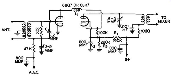
Fig. 5.17. A cascade R.F. amplifier.
A recent circuit development makes it possible to achieve low noise with good gain. The name of this circuit is "cascode" and its schematic is shown in Fig. 5.17. Basically, it consists of two triodes connected in series, that is, the plate of the first section goes directly to the cathode of the second section. The same current flows through both tubes, and the amount of cur rent is controlled by the bias on the first triode.
The input tuned circuit of this series amplifier connects to the control grid of the first triode; the output circuit is in the plate lead of the second triode. The first stage is operated as a conventional amplifier; the second stage is employed as a grounded-grid amplifier. The coil L1 between both stages serves to neutralize the grid-to-plate capacitance of the first triode (with help from capacitor C1) and it is designed to resonate with the grid cathode capacity of the second section. While L1 thus aids the stability of this combination, it is also largely responsible for the low noise qualities of the cascode circuit.
Direct coupling is used between the first triode plate and the second triode cathode. With cathode feed to the second triode, C 2 is used to place the grid at R.F. ground potential. Since the two triode sections are in series across a common plate supply, the cathode of the second triode is 125 volts positive with respect to chassis ground. A divider across the plate supply, consisting of R1 and R2 , places the grid of the second triode at a sufficiently positive potential (with respect to its cathode) for proper operating bias.
The cascode circuit is being widely used by many receiver manufacturers.
EXAM
1. In what ways do high-frequency tuning circuits differ from low-frequency tuning circuits?
2. What ordinarily happens to the Q of a tuning circuit as its frequency is raised? Why?
3. What is slug tuning?
4. Why is a high L to C ratio desirable in a tuning circuit? When is it purposely lowered?
5. Why do we find four parallel wires used on some permeability-tuned coils? How could a single wire be made to produce the same effect?
6. What is the reason for the uneven turn spacing found on some coils?
7. What properties of a transmission line enable it to be used for tuning?
8. How can a coaxial transmission line be employed for tuning?
9. Describe the operation of a parallel-wire transmission line tuner.
10. Draw the circuit of a grounded-grid amplifier. What advantages does this amplifier offer over the amplifier of Fig. 5.16A for high-frequency operation?
11. What is a cascode amplifier? What advantages does it possess that make it suitable for use as an R.F. amplifier?
12. Draw the circuit diagram of a cascode amplifier.
+++++++++++