Phase Modulation. It has been demonstrated that intelligence can be imposed onto a carrier by variation of its amplitude or its frequency. The only remaining electrical property is the phase of the carrier. By suitably shifting the phase of the wave in response to an applied audio-modulating voltage, we can accomplish the same transfer of intelligence as we have seen occur in the previous two methods of modulation.
A comparison is perhaps the simplest way of approaching phase modulation. Consider two carriers that are being transmitted at the same time, both of equal frequency but differing in phase by 45°. The phase difference merely indicates that when the voltage of one wave reaches its peak, at any one instant, the other carrier is 45° from its peak value. Fig. 2.1 illustrates just such a situation. In all other respects the signals are equivalent. If nothing is done to alter this phase relationship between the two carriers, nothing will be heard at the output of a phase-modulation receiver.

Fig. 2.1. Two carrier waves differing by 45°.
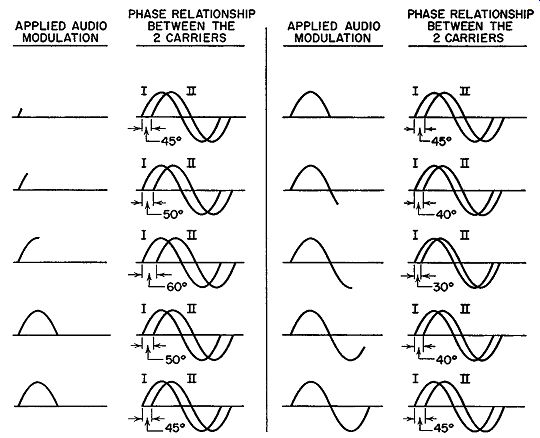
Fig. 2.2. A simplified illustration of phase modulation. Carrier I remains
fixed while the phase angle between it and carrier II varies.
But suppose the phase relationship is altered in a definite rhythm or pattern-perhaps in accordance with the amplitude and frequency of an applied sine wave. Let these audio variations be applied to the carrier that lagged by 45°. The other carrier will be kept fixed. Then the phase of the carrier to which the modulation is applied might swing, under the action of the audio signal, from 45° lag to 60° lag (see Fig. 2.2). The 60° lag would occur when the audio-modulating signal was at its positive peak. As the audio voltage decreased from this peak toward zero, the carrier would follow suit by slowly returning to 45° lag, its normal position. On the negative half cycle of the audio signal, the phase lag of the carrier shifts in the opposite direction, or toward a value less than 45 °. This is opposite to its increase in phase when the audio signal was on the positive half cycle. At the negative audio peak the phase of the carrier would be brought to 30°. Note that this point is just as far below the normal value of 45° as 60° is above. From the cycle's maximum negative peak back to zero the phase returns, in step, to 45°. This phase shift represents one complete cycle for the audio-modulating voltage. It would occur over and over again as long as the modulating signal was active. At the proper receiver, the phase variations would be converted to the corresponding audio sound much the same way as an FM receiver converts frequency modulation into sound. Instead of AM or FM we are dealing with P-M, or phase modulation.
Factors Affecting Phase Shift. The rapidity of phase shift from one value to another is determined by the modulating signal frequency. How ever, the number of degrees through which the carrier is shifted during modulation is dependent upon the strength of the audio signal. A weak signal, for example, might shift the phase only to 50° at its positive peak and 40° at its negative peak. A stronger signal at the microphone could, at its peak, cause a considerably larger phase shift. The receiver, working on phase differences, would note the different shifts and respond accordingly. This relation of phase shift to strength of the audio signal is entirely analogous to FM, where a strong audio signal is needed for a wide frequency shift and a weak modulating signal produces a small frequency shift. At the FM receiver, the discriminator is sensitive to frequency differences and derives the appropriate audio variations from the carrier. In both FM and P-M, the total power remains fixed throughout the entire sequence of modulation. There are other points of similarity between the two systems, with the same mathematical design formula applicable to both.
The foregoing illustration is useful in introducing the basic concepts of phase modulation, but it does not clearly indicate how frequency modulation results. For this, a vector approach can be better employed.
Elementary Vectors. A vector is a shorthand method of illustrating certain facts much as numbers represent a shorthand method of expression.
When we write the number 15 to designate a group of objects, we mean 15 individual pieces or parts or units. The number 15 saves us the trouble of drawing 15 squares, or circles, or other geometrical figures to indicate the total of such units.
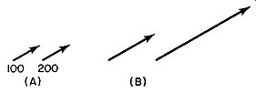
FIG. 2.3. Vectors represent definite forces and the directions in which
they act.
There are certain types of physical quantities which possess not only magnitude but also direction.
The magnitude may be indicated direction? For this we require an arrow. Thus a force of 100 pounds produced by a tractor pulling a block of wood, for example, in one direction could be illustrated by a number and an arrow, as shown in Fig. 2.3A.
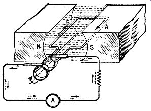
FIG. 2.4. The basic arrangement for the generation of an alternating
voltage.
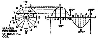
FIG. 2.5. The variation in a-c voltage with coil position.

FIG. 2.6. Substitution of vectors in place of the rotating coil. The
arrowed vectors indicate the coil position at various instants.
A simpler method, however, is to have the length of the arrow indicate the magnitude of the force, and the direction in which the arrow is drawn denote the direction in which the force is acting. If the arrow is made ½ inch long for 100 pounds of force, then an arrow 1 inch long would represent a force of 200 pounds (see Fig. 2.3B). Vectors Applied to Radio. Of specific interest is the application of vectors to radio or, more specifically, to electric waves. We know, from our first lessons in radio, that an alternating current is produced whenever a coil is rotated in the magnetic field between two magnets (see Fig. 2.4). If the field is uniform, the voltage produced across the output terminals of the coil in a sine wave. In Fig. 2.5 we see that the voltage generated depends upon the position of the coil in the magnetic field. This may be expressed mathematically by the formula
e = Emax. sin 8 (1)
... where e = instantaneous value of the voltage developed when the coil is at some angle()
Emax. = maximum value of the voltage
() = angular position of the coil
Since the position of the coil determines the amount of voltage generated, suppose we replace the coil by a vector, as shown in Fig. 2.6. The value of the voltage, at each instant, is then given by the vertical height of the vector, this vertical being proportional to the sine of the angle 8. When the vector is placed horizontally, the angle 8 is zero. This makes sin () equal to zero (see Fig. 2.7A). From formula (1), e = 0 when () = 0 and no voltage is generated. At some other angle, say 30°, the voltage generated is
e = Emax. sin 30°.
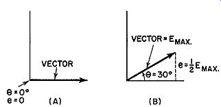
Fig. 2.7. The value of the generated voltage depends upon sine of the
angle, ().Since sin 30° =½, then e = ½ Emax.
This is shown with the vector placed at an angle of 30° with the horizontal (Fig. 2.7B). A vertical line dropped from the head of the arrow will then be½ as long as the length of the vector.
If the length of the vector is made equal to the value of Emax., say 100 volts, then the length of the vertical will represent 50 volts. Thus, the vector is made equal to the peak voltage of the sine wave; a vertical line dropped from the head of the arrow to the horizontal axis represents the voltage generated when the coil is in the position of the vector.
The rapidity with which the vector rotates or makes one complete revolution is the same as the frequency of the a-c wave it represents. If the frequency of the wave is 10,000 hz, then the vector will rotate 10,000 times in one second.
Two waves acting at the same time can be represented by two vectors, as in Fig. 2.8. Any phase difference between the waves is indicated by the relative position of their vectors. Two vectors displaced by 45° represent two electrical waves 45° apart in phase. Here again we note the simpler notation made possible by the use of vectors.

Fig. 2.9. The addition of two vectors that are in phase, i.e., point
in the same direction.

Fig. 2.8. A comparison between the vector and the conventional methods
of illustrating a 45° phase difference between two waves.
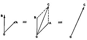
Fig. 2.10. The addition of two out-of phase vectors.
Many times, when two waves are present in the same circuit, we wish to ascertain the total effect and not merely the individual results. If the voltages are in phase, given by two parallel vectors, they may be added directly (see Fig. 2.9). However, voltages generally differ in phase and direct addition is no longer possible. In Fig. 2.10 two vectors, OA and OB, represent two voltages that differ in phase. The resultant of the two is obtained by constructing a parallelogram, OBCA. Line BC is parallel and equal to OA; line AC is parallel and equal to OB. The diagonal drawn between points O and C is the resultant of the vectors OA and OB. Another interpretation of the resultant is to consider vector OA as forcing a particle to move from 0 to A, while vector OB forces it to move from A to C. Hence, if two forces, OA and OB, were applied simultaneously to the particle placed at point 0, the particle would be forced to travel along line OC.
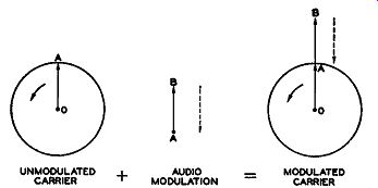
Fig. 2.11. Amplitude modulation demonstrated by vectors.
Vectors Applied to Modulation. The vector concept lends itself quite readily to the three types of modulation. For AM, in Fig. 2.11, the carrier vector OA is rotating at a frequency determined by the oscillator in the transmitter. Let this be 1000 khz. In one second, therefore, there are 1,000,000 complete revolutions producing 1,000,000 cycles. When audio modulation is added, represented by vector AB, the length of the overall vector OB will depend on how AB varies from moment to moment. When the audio voltage is at its peak, AB attains its greatest length; for weaker modulating signals, AB becomes small.
The complete picture shows OA, the carrier vector, rotating rapidly at the radio-frequency rate while the length of OA + AB varies slowly as the strength of the audio signal increases and decreases. This is evident, too, in Fig. 2.12, where one audio cycle covers may carrier cycles. Since in Fig. 2.11 AB is governed by the audio-modulating voltage it will either add to OA or be out of phase (oppose OA) by 180°. Again, reference to Fig. 2.12 will show the same thing to be true there. Note that AB can either add to OA or subtract from it, but nothing more, since this is amplitude modulation and only the amplitude of the vector OA can change.
In FM, the length of the vector OA remains constant while the speed (frequency) at which it rotates varies from instant to instant according to a pattern set by the audio modulation. Thus, at one moment, it may be spinning around faster than normal; at the next, back to normal; a second later, slower than normal, and so on. These changes represent our frequency variation or modulation and can be detected by the proper receiver.
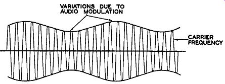
FIG. 2.12. The customary method of indicating an amplitude-modulated
wave.
Now we come to phase modulation where we operate on the relative phase of a carrier, leaving the amplitude and frequency fixed. However, as we shall soon see, varying the phase of a wave results, indirectly, in frequency modulation and this can be detected by an FM discriminator.
FM from P-M. In the vector diagram illustrating phase modulation, Fig. 2.13, OA, as before, is the carrier to be phase modulated. It rotates at the frequency of the carrier. OB, another vector, is separated from OA by 45°. This vector is shown for reference only, and will aid in visualizing the phase changes of OA. Although it is not necessary to include OB in each diagram, it may help to understand the phase changes of OA by considering OB as always present.
The frequency and amplitude of OA are kept fixed. If now we vary the phase of OA (with respect to OB) then, as OA rotates, it will "wobble," or fluctuate back and forth, about its mean position.
Suppose that at the instant the audio modulation is applied, the vector OA is at point 1 in Fig. 2.13. Fig. 2.13. The phase variation of a carrier that is being phase-modulated by an audio signal.
Due to the acting modulation, its phase (or position) is shifted to point 2. From position 2, the audio signal brings the vector back to position 1. From position 1 the vector goes to position 3, due, this time, to the opposite half cycle of the audio wave. To complete the cycle, the vector goes back to position 1, the mean point. Thus, under the force of the applied audio voltage, the phase of OA changes from position 1 to position 2, back to 1, then to position 3, and finally back to the starting point, position 1. This represents one complete cycle and recurs at the audio frequency.
Now let us see what is necessary when we shift the phase of a wave. To advance the wave position where it is slightly ahead of its normal position, such as shifting it from position 1 to position 2, we must momentarily cause it to speed up for if it had continued moving at its normal speed, it could never have reached the advanced position. From point 2, back to point 1, necessitates a gradual lessening in the speed of rotation. From the normal position to position 3 means a still further decrease in speed on the part of the rotating vector. Finally, to complete the cycle, the vector is brought back to its original position at 1 by a corresponding speed increase.
For the sake of simplicity, the vector OA is stopped while the various positions assumed due to phase modulation are shown. Actually OA is revolving at a tremendous rate while the phase varies, relatively, very slowly.
But the overall frequency change due to these phase variations still takes place. This is the important point. Each time the carrier vector wobbles back and forth to reach the new phase positions dictated by the audio modulation, we find the frequency also changes in order to have the vector reach the new positions.
In Fig. 2.13, points 2 and 3 were the maximum phase shifts of the carrier vector OA. If the amplitude of the driving audio voltage increases, for example, then the phase shift will increase and OA will have to travel through a greater angle. Conversely, a smaller audio voltage results in a smaller shift.
As we shall soon see, the size of the shift has a very direct bearing on the amount of indirect FM generated.
The average frequency of the rotating vector OA, throughout the entire process, remains constant. This must be so, of course, since we are not, directly, varying the frequency of the wave. But at those instants when the phase of OA is changing, its instantaneous frequency is either increasing or decreasing. If this were not so, then how could OA ever reach the different phase positions rotating at its fixed rate? Obviously it could not. Note that what we are doing is adding sufficient change, either positive or negative, to a fixed frequency to permit the carrier to reach the desired phase position.
Distinguish this from "pure" FM where the carrier frequency itself is being directly affected and shifted in response to the modulating voltage. In the end, both may result in frequency modulation, but it is important to realize that a difference does exist.
Factors Affecting Indirect FM. The amount of indirect FM that is formed by phase modulation depends upon two factors. First, there is the extent of the phase shift. Quite naturally, the larger this phase shift, the more the carrier frequency must be altered to meet the new condition. The two are directly proportional to each other. Second, there is the frequency of the modulating audio signal. If the audio frequency is high, the shifting from one position to another will have to take place in less time, which means that, in any one instant, a greater carrier frequency change must occur. The result---more frequency modulation. On the other hand, if the same phase shift occurs at a lower audio frequency, the rapidity with which the carrier must change decreases. Consequently, the equivalent carrier frequency change decreases. As with phase shift, the extent of the indirect FM formed varies directly with the audio-modulating frequency.
Because of the importance of the concept of forming frequency modulation from phase changes, it may prove helpful if we consider the same problem from still another angle.
When the phase of a carrier is shifted, so that it differs from another constant carrier by more than it did previously, it means that each wave must go through its cycle just a trifle faster in order to attain the necessary shift within the allotted time. Consider the two waves, A and B, shown in Fig. 2.14. Wave A is untouched by the modulating voltage and completes its cycles with unvarying regularity. Wave B, however, is subjected to a modulating voltage which causes it to shift in phase, relative to wave A, by 30°. The full shift must be completed by the time position C is reached.
In order to attain this variation, each of the four cycles shown must con tribute a portion of this shift, all contributions adding to the necessary 30°. But for each wave to assume an additional amount means that, besides the regular 360°, each must add a little extra. This can only be accomplished if each wave swings through its cycle of variations a trifle faster than it normally would. By the time point C is reached each cycle has added sufficient phase variation to fulfill the required 30°. Henceforth, with no further variation, wave B will reach its maximum positions (and minimum positions) 30° ahead of wave A; its frequency will continue at the same rate as that of wave A, exactly as it existed prior to the modulation. It is only during the shifting in phase that the frequency variations appear and, coincidentally, the indirect FM. When the shifting ceases, indirect FM disappears.
To demonstrate how the degree of phase shift and the rapidity with which it occurs affect the indirect FM, consider the following two illustrations. A carrier of 90 mhz (90,000,000 hz) is to be shifted ahead in phase to a maximum of 50°, this to be accomplished in 1/1000 of a second, as determined by the audio-modulating frequency. In 1/1000 of a second, 90,000 cycles of the carrier will occur. To complete a 50° shift in this interval, each carrier cycle must contribute an additional 50/90,000 degree, or approximately 0.0005°. To achieve this, the frequency of each wave must be increased slightly. This increase produces the indirect FM. The same line of reasoning would apply if the wave were to drop 50° behind, except that now each wave loses 0.0005° from its cycle. The result-a de crease in frequency.
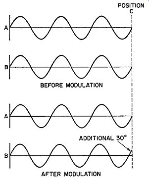
Fig. 2.14. Prior to modulation, carriers A and B are in phase. After
modulation, B leads A by 30°.
If we maintain the phase shift at 50°, but decrease the time in which this change must be attained, then we have the equivalent of an increase in audio modulating frequency. Assume the completion of the phase shift is to be accomplished in 1/10,000 of a second. In this time interval, the number of carrier cycles occurring will be reduced from the previous 90,000 to 9000. For the 50° shift, we calculate that 50/9000 or approximately 0.005° are needed from each cycle compared to the 0.0005° given above. The larger the shift of each wave, the greater its frequency change.
Expressed in mathematical terminology, the extent of the indirect FM formed through phase modulation is given by where
t:,.F (frequency shift) = f X M sin wt
f = the frequency of the audio-modulating voltage ( or any other voltage) that is causing the phase shift t:,.() = the maximum angle through which the carrier is shifted
sin wt = the sinusoidal variation of the applied audio voltage
The inclusion of the term "sin wt" indicates, mathematically, that the audio voltage is a sine wave and, hence, its force varies sinusoidally. As a result, the phase shift follows suit. Since all complex waves can be resolved into pure sine waves, the expression is applicable to all types of electrical waves employed in communications.
A comparison of the foregoing equation with true or direct FM reveals the differences between them. In direct FM the value of the carrier itself swings between its maximum limits, say 75 khz, about the central or resting position. The carrier is actually being shifted directly by the modulation.
In indirect FM, produced by the phase modulation, the carrier is not actually shifted directly by the modulation. Rather, the effect of the phase shifts is to either add or subtract frequency variations to the fixed carrier.
In the next Section we will use these facts to demonstrate why FM is so effective in reducing interference.
EXAM
1. Differentiate between phase modulation, amplitude modulation, and frequency modulation.
2. Name and explain the factors which affect the phase shift of a phase-modulated wave.
3. Why are vectors useful in describing phase modulation? Could they be used to illustrate amplitude and frequency modulation?
4. Illustrate vector addition.
5. How do we obtain FM from P-M?
6. Distinguish between indirect and direct frequency modulation.
7. List the factors which affect the amount of indirect FM produced from a phase-modulated carrier.
8. What commercial system currently employs P-M to produce an FM wave?
9. Two vectors are displaced from each other by an angle of 50°. One vector is 10 units long, the other is 7 units long. Draw these to scale and then determine graphically the length of the resultant vector. What angle does this resultant vector make with the 10-unit vector?
10. Two vectors are 180° out of phase. One vector is 12 units long, the other is 21 units long. Draw the resultant vector. What is the angle between the resultant vector and the longer vector?
11. A carrier is being phase-modulated by a 1000-cycle audio sine wave. At what points throughout the modulating cycle is no indirect FM being produced? Why?
12. In the preceding example, at what time during the modulating cycle is the maximum amount of indirect FM being generated? Why?
+++++++++++