Interference Suppression, FM's Main Advantage. Frequency modulation was popularized because of its effectiveness in combating interference against which amplitude modulation operationally is seemingly ineffectual.
The fact that a wider audio-frequency range may also be included without unduly increasing the bandwidth required by an FM station is advantageous but not overly important. There is much evidence that the inclusion of audio frequencies above 5000 cycles is not greatly desired by 90 percent of the listeners. Fidelity is another controversial issue. If fidelity is interpreted to mean the true reproduction of sound, than an AM system is just as capable of good fidelity as any FM network. By and large, interference suppression is the chief reason for the present popularity of FM. The word "interference" is applied to any voltage arriving at the input of a receiver or generated in the receiver itself which obstructs, to any noticeable degree, the satisfactory reception of the desired signal. Obviously, there are many sources that may produce interfering voltages, but only those that have been proved by practical experience to be the most important will be investigated. The others either occur too infrequently or else possess in sufficient strength to warrant a separate discussion.
INTERFERENCE FROM OTHER STATIONS ON SAME FREQUENCY
One of the most prevalent annoyances in an amplitude-modulated receiver is the piercing beat-note whistle that is heard whenever two signals operating within the same channel are received simultaneously. The whistle is produced whenever the difference of two carrier frequencies is equal to a frequency in the audible range. Within the same channel, this difference seldom exceeds several hundred cycles. As they are close in frequency, the two signals pass through all the circuits together until the 2nd detector is reached.
Here they are converted to their original audible form and the beat note appears. It is impossible to remove the beat note by any adjustment in the receiver because both signals are operating within the same band. A directive antenna favoring the desired signal may prove helpful but, in most cases, hardly feasible because other desired stations at other frequencies arrive from different directions. At night the interference becomes stronger because of improved propagation characteristics. In AM, the interfering signal need be only 1/100 as strong as the desired signal to make itself heard. In other words, a noise-to-signal ratio only 1 to 100 will cause noticeable disturbance.
With FM, a considerable improvement is possible and the desired signal need only be twice as strong as the interference to completely override it. To see why this is so, we shall examine closely the action of an FM signal when in the presence of an interfering voltage of smaller amplitude.
Amplitude and Phase Modulation from Interference. In Fig. 3.1 we have two signals, separated slightly in frequency and differing in amplitude.
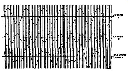
Fig. 3.1. The combination of two carriers to form a resultant which
is amplitude and phase-modulated.
Both are plotted separately to scale. Below these two waveforms is the resultant derived by combining the two waves at every point. If we examine the resultant closely and compare it with the desired signal, we note two differences. First, the amplitude of the resultant is not constant, but varies at a rate equal to the difference in frequency between the two received signals. Thus, if both voltages differ in frequency by 1000 cycles, the amplitude of the resultant will increase and decrease 1000 times per second. In an AM receiver, this fluctuation would be "skimmed off" (detected by the 2nd detector) and heard as a beat-note whistle in the loudspeaker. What the effect is on an FM receiver soon will become apparent.
We note, as a second effect of the mixing of two signals, that, although the average frequency of the resultant is the same as the larger signal, the two waves (the larger or desired signal and the resultant) do not always have the same relative position. At times the resultant will lead the desired signal in phase, at other moments there will be no phase difference, and, finally, there will be a lag. In other words, with respect to the original desired signal, the resultant has become phase-modulated. From preceding paragraphs, we are aware that, indirectly, frequency modulation is also produced. The amount of the indirect FM produced is directly proportional to the phase shift introduced into the resultant wave and to the frequency difference between the two carriers arriving at the receiver. This follows from the formula previously given.
The degree of phase difference caused by the two interacting waves depends wholly upon their amplitude ratio. When the ratio is 2 to 1, the maximum angle of phase shift produced is slightly under 30°. This means that the resultant wave leads and lags, alternately, the larger component by this amount. At larger ratios of desired signal to interference, the phase shift is even less. The difference in frequency between the two carriers will set the rate of variation of the phase shift.
Let us pause for a moment and consider these conclusions, for they hold the secret of FM effectiveness in suppressing interference. Whenever two voltages are present at the input of an FM receiver, then Fig. 3.1 demonstrates that their resultant will be amplitude- and phase-modulated. The amplitude variation is responsible for the piercing beat-note whistle that is so annoying in AM sets; the phase modulation contributes indirect frequency modulation.
If we could eliminate both of these modulations from the resultant signal we would have the desired signal with no variations, since it is only in these two respects that the desired and resultant signals differ. Then, too, we should have effectively eliminated the disturbance of the interfering voltage, since it was this voltage that acted with the desired signal to cause these variations.
Eliminating Amplitude Variations. The simpler to remove is the amplitude modulation. This is accomplished by means of the limiter stage in the FM receiver. Within limits, different input voltages to the limiter produce a constant output. By this device we accomplish the eradication of all amplitude modulation, leaving only the phase modulation. In this respect, then, we have made the resultant wave and the desired signal similar.
Minimizing Phase Modulation. There is no practical method currently available for removing the FM produced by the phase variations and still receive the desired FM signal. But, if we cannot eliminate the indirect FM, we can, at least, reduce it to the point where it becomes negligible when compared with the regular frequency variations of the FM signal. It is for this reason (among others) that we resort to wide-band FM. The degree of the indirect FM formed from phase modulation has been shown in Section 2 to depend upon f 6.0, where f is given in cycles and 6.0 is expressed in radians. A radian is equal to 57.3°, which means that there are 2 pi, or 2 x 3.1416, radians in 360°. When the two reacting signals differ in amplitude by a ratio of 2 to 1, the maximum phase shift introduced in the resultant wave is approximately 30° or about ½ a radian. By way of illustration, let us say that the frequency difference (f) between the two carriers is 1000 cycles, or 1 khz, and the signals differ in strength by 2 to 1. Substitution of these values in the foregoing formula indicates that a frequency shift of 1000 x 0.5 or 500 cycles occurs. The shift is, periodically, above and be low the average frequency of the stronger signal. In this instance, the frequency variations shift at a rate of 1000 times a second, which is the value off.
Now compare this variation with ordinary FM. F.C.C. regulations permit a broadcast station's carrier to be shifted from its assigned position to a maximum of 75 khz, or 75,000 cycles. The interference, in the above example, indirectly produced a frequency shift of only 500 cycles. Certainly this is insignificant when compared to the audio intensity developed by a swing of 75,000 cycles! And, remember, for 500 cycles to be produced, the interfering voltage had to possess one half the amplitude of the desired carrier. In the more usual case, the ratio of the noise-to-signal voltage is much smaller, say 1 to 10 or 1 to 20. Under these conditions the suppression is better still.
Thus, the use of wide-band FM completely swamps the small FM modulation developed indirectly from the interference. Herein lies the power of FM. However, as we reduce the swing of the desired carrier, the effect of the interference becomes more and more important. For best reproduction, wide-band FM is required.
Frequency Separation of Interfering Signals. There is another important fact to be learned from the equation 6.F = f 6.0. As we bring the desired carrier and the interfering signal closer in frequency, f becomes smaller. If the two signals are at the same frequency, their difference (f) becomes zero and no indirect FM appears (6.0 times zero is zero). In other words, the interference can have no effect. The greater the frequency separation between the signals, the greater the indirect FM produced. But even this has a limit. First, the farther the interfering signal frequency is from the center of the frequency selectivity of the tuned circuits, the more its intensity is decreased by the selectivity of the receiver circuits themselves.
Second, the frequency difference f, if greater than 15,000 cycles, becomes in audible to most people and cannot be heard at the output. There is still another effect tending to decrease the interference when the signals are widely separated, but this is reserved for a later section. In summary, we see that when the interfering signal approaches the frequency of the desired signal, the ft:,.() relation works against it whereas, when the two are widely separated, the selectivity of the circuits and our aural limitations impose other barriers.
In amplitude modulation the aural effect of bringing two frequencies together is to produce a lower beat note. This, however, does not affect the loudness of the beat-note whistle. From this viewpoint alone, the situation is more favorable for FM. Add the fact that stations can differ in amplitude by a ratio of 2 to 1 for FM and still come through clear and free and we see the great improvement that the newer system offers. It also makes possible the closer location of broadcast stations. Aiding the latter point is the use of high frequencies for FM operation. At the high frequencies, radio waves travel essentially in straight paths from transmitter to receiver. The ionosphere cannot be used to reflect the waves because penetration is accomplished without appreciable bending. Hence, long distance interference from other stations is avoided. Admittedly, though, this is not a property of either FM or AM, but of the wavelengths employed. If we operated the amplitude-modulated transmitters in this upper range, the interference from a distant station would also be decreased.
As long as the desired signal is at least twice as powerful as the interfering signal, only the desired station will be heard in the loud-speaker. As the two signals approach each other in strength, the extent to which the interfering voltage makes itself felt increases sharply. When this signal finally reaches the level where it is stronger than the desired signal, a transition occurs and it assumes full control, completely drowning out the other carrier. The worst situation is in effect when both voltages are equal, for now no clear-cut tendency exists one way or other. However, the moment one signal becomes even a trifle stronger the response changes, with the stronger signal assuming noticeable control. The process is complete when the ratio reaches the 2 to 1 point.
Domination by the Stronger Signal. The reason for the sharp transition in control when one signal becomes even slightly stronger than the other can best be appreciated by vectors. Consider two signals (Fig. 3.2), both present at the discriminator of an FM receiver. The larger vector, 1, rep resents the desired signal; the smaller vector, 2, is the interfering signal; and R is their resultant. At the output of the stage it is not 1 or 2, separately, that is heard, but the resultant. Our interest is chiefly in the indirect FM produced by the interacting of 1 and 2. Any amplitude variations will be effectively eliminated by limiters preceding the discriminator. The signal, at the discriminator, can be made wholly frequency-modulated.
In Fig. 3.2A, vector 1 is operating at our assigned frequency of 90 mhz.
This means that it is rotating about point O at 90,000,000 times a second.
Vector 2 is also rotating but at its own rate, say 90,005,000 times a second.
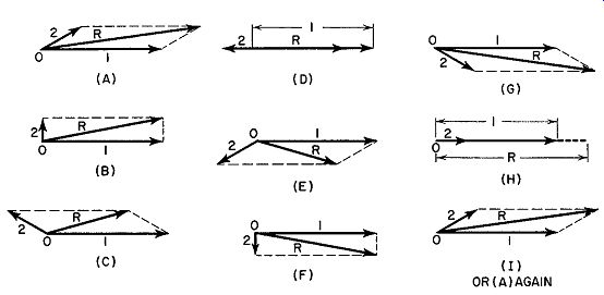
Fig. 3.2. The resultant wave (R) produced by the interaction of a strong
signal (1) and a weak interfering signal (2).
Their difference is 5000. Vector R will also rotate about O, but its speed will depend upon whether 1 or 2 is greater in amplitude. This will become evident as we proceed.
Since signal 2 has a slightly higher speed (frequency) than 1, it means that 2 will gradually move farther and farther away from its relative position shown in Fig. 3.2A. At one point in time, it may have advanced from vector 1, as shown in B; at some later instant it would be as seen in C (if we momentarily stopped the motion), then D, etc., until gradually it would work its way back to the position shown in A. The sequence is repeated for as long as the rotation is allowed to continue. If vector 2 has a lower frequency than vector 1, it would lose instead of gain a little each instant and so appear to move in the opposite direction with respect to vector 1.
The reader will note the similarity between this action and that of two cars speeding around a large oval. The speedier car will gradually increase its lead over the slower car. If this is allowed to continue long enough, then, in time, the faster car will be one full lap ahead of the slower car. At this point both cars are again racing alongside each other.
If we stop at each of the instants shown in Fig. 3.2 and draw the resultant vector, we see that it fluctuates about vector 1. At C it has shifted to its maximum position ahead of vector 1 and at E it has fallen to its maximum position behind vector 1. At other times it assumes some intermediate position. These fluctuations represent the phase modulation of vector R. As R rotates rapidly about point 0, it is also wobbling back and forth about the mean positions of vector 1. In other words, vectors R and 1 possess the same average frequency, but R differs in amplitude and phase from 1. The amplitude fluctuations are suppressed by the limiter stage (or stages), whereas the phase variations will, as already noted, cause frequency modulation. The in direct FM depends upon the maximum angular shift between 1 and R and the speed with which R fluctuates about 1. All this, it will be recognized, has been discovered before. That it appears here is partial evidence that we are on the same track.
In this first example, vector 1 was very much larger than vector 2. This was done purposely in order to show clearly the effect of a large desired signal. In the next case, let vector 1 remain larger than 2, but only slightly so.
Now let us see what happens. The action is illustrated in Fig. 3.3.
FIG. 3.3. The amplitude and phase variation of a resultant (R) carrier due to the interaction of two signals. The small arrows on R indicate whether its phase (with respect to the desired signal, 1) is going in a positive or negative direction.
The first evident conclusion to be drawn is that here the resultant fluctuates between wider limits. But since it still fluctuates about vector 1, its frequency is that of 1. If its frequency equaled that of 2, then it would follow this vector around, with 2 as its center position. This, however, does not occur. Hence, we conclude that by bringing the two signals closer in amplitude we only succeed in causing more phase modulation in the resultant vector R. Its average frequency is still the same as that of the larger signal. What we hear from the output of the receiver is signal 1, but with sufficient interference to cause distortion. This, it will be recalled, is another conclusion previously discovered.
Now, if we make signal 2 greater than signal 1, what will happen? We have merely to return to Fig. 3.2 and transpose the numbers 1 and 2 (vectors) to see the result. The resultant begins to fluctuate about vector 2 and the signal heard in the loudspeaker is determined primarily by 2, with a certain percentage of indirect FM added, due to signal 1. The transition from vector 1 to 2 is sharp and demonstrates why the predominant signal assumes control in FM systems. Once the ratio of the two signals reaches 2 to 1, the FM effect of the smaller on the larger, with wide-band FM modulation, becomes negligible. This is true whether the interfering signal is another station or just plain noise of any type.
ADJACENT CHANNEL INTERFERENCE
It is not at first apparent why any interference is caused by stations on the channels adjacent to the desired signal, but such interference is possible.
Due to this possibility, it is the practice of the F.C.C. never to permit stations to broadcast on adjacent bands in the same community. The closest that two stations in the same region can transmit (in frequency) is on alternate channels. Thus, if the three frequencies 90.1 mhz, 90.3 mhz and 90.5 mhz are available, only 90.1 mhz and 90.5 mhz would contain stations, at any one time, in any one service area. In some other region, however, it would be perfectly feasible to have a station assigned to the 90.3 -mhz frequency.
The interference between two stations transmitting on adjacent bands is a result of:
1. The type of selectivity curve designed for most commercial receivers.
2. The fact that sidebands of the two adjacent stations can interact to form audio frequencies at the output of the discriminator.
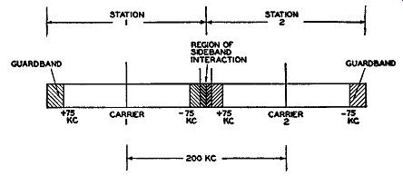
FIG. 3.4. In the darkened region between station 1 and station 2 it
is possible for their sidebands to interact and produce interference.
It was found in a previous section that FM interference produced when two stations operate on the same band is due to the introduction of phase variations. The frequency of the audio voltage developed from the phase modulation is equal to the frequency of separation of the two carriers. Obviously, if the interacting carriers differ by more than 15 khz, no audible interference appears at the loudspeaker. When one of the carriers arriving at the receiver is centered on an adjacent channel, the possibility of its creating audible interference in reception is non-existent because of the 200- khz frequency difference between the carriers. But consider the possibility of interference when the sidebands of each carrier react with each other. These would be capable of producing an audible note if both sets of sidebands extend into their respective guardbands. This can occur on strong modulation.
The region that is sufficiently close to an adjacent guardband to cause audible interference is indicated in Fig. 3.4.
The selectivity characteristic of the tuning circuits of the receiver must also be a partner to the action, since a sharp cut-off at the edge of the desired channel would prevent reception of adjacent channel signals (see Fig. 3.5).
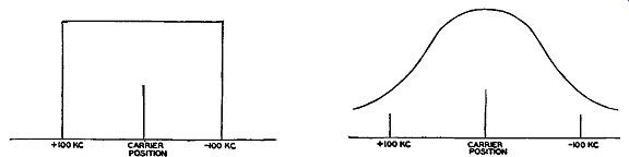
FIG. 3.5. Perfect response characteristic for receiver tuning circuits.
FIG. 3.6. Practical modification of Fig. 3.5.
In commercial receivers, the added expense necessary to include sharp cut-off resonant circuits is prohibitive. As a compromise we find the familiar tapered response shown in Fig. 3.6. With this form, it is quite possible to receive the sideband frequencies of adjacent channel stations. If, during any portion of the modulation, the adjacent signal is stronger at the discriminator than the desired frequencies, the desired signal will be ruined. On the other hand, if the desired signal has a greater intensity at the discriminator, no distortion will be present.
The solution of interchannel interference lies in good selectivity response of the receiver plus the prohibition of near-by adjacent channel stations.
The latter has been accomplished already by existing F.C.C. regulations and the former is a matter of individual design. As it is, the situation using FM is considerably better than the corresponding situation for AM for several reasons.
1. The use of a guardband on FM decreases the possibility of signals on adjacent bands interfering with each other.
2. The line-of-sight transmission characteristics of the higher radio frequencies limits the interference from stations in other areas. At the lower AM frequencies, long distance propagation is always possible, especially at night when the attenuation is less.
3. The inherent characteristics of the FM system where a 2 to 1 ratio causes the "practical" elimination of the weaker signal. Using AM, this does not occur until the stronger signal is 100 times more powerful than the weaker one.
In neither system are stations in the same service area placed on adjacent channels. However, because of reason No. 2 above, the advantage of such a condition benefits FM more than it does AM.
STATIC
Perhaps second in importance as a disturbing influence in radio reception is static. This is especially true during the six warmer months of the year when thunderstorms are more prevalent. During a local thunderstorm, only the very loudest programs can be heard, and even these with difficulty. The strength of the electrical waves set up is strong enough either to completely drown out radio signals or else present sufficient interference to destroy the clarity of reception. This is the existing situation with AM and its only solution, at the time of this writing, has consisted of the following:
1. The insertion of limiters in the audio section of the set. These stages limit the maximum amplitude of all signals and prevent thundering crashes of volume accompanying a strong outburst of lightning. The limiter, however, is quite ineffective when the incoming interference is of the continuous, crackling variety. As the name suggests, these devices only limit incoming bursts. The signal, during these moments, is still ruined.
2. Designing the receiver selectivity to include no more than the necessary commercial bandwidth, 10 khz wide. It has been discovered that the energy contained in a static outburst is spread over many frequencies, with the greatest concentration at the lower frequencies. Hence, the narrower we make the bandwidth to which the receiver will respond, the less static noise we will obtain.
Beyond these two refinements of an ordinary receiver, very little can be done to overcome the effects of static. With FM, we not only have the ad vantage of the 2 to 1 ratio, but also the advantage of frequency. Since most of the energy of an outburst is located at the low frequencies, very little reaches the high-frequency bands allocated to FM. In addition disturbances due to distant thunderstorms seldom, if ever, reach the receiver because of the limited transmission range of high frequencies.
THERMAL AGITATION AND TUBE HISS
Even in the complete absence of natural disturbances and interfering stations, there remains a practical limit to the weakest signal that can be received by any set. The limit is fixed at the first or second stages of a receiver and is due to two main sources, thermal agitation and tube hiss.
Thermal agitation arises from the random motion of electrons in any conductor. The movement of the electrons, in both directions, constitutes a current flow. Since there are usually a few more electrons moving in one direction than in the other, a voltage is set up across the conductor which is proportional to the net current flow and the value of the conductor resistance. The polarity of the voltage due to thermal agitation changes constantly, depending on the direction in which the maximum number of electrons are moving. Because of this, there is no definite pattern to the random voltage, or, for that matter, any one frequency at which the electrons move.
It has been found that the energy of the disturbance is distributed uniformly throughout the entire frequency spectrum used for communications.
The amount of voltage that is developed by thermal agitation in conductors can be computed from the following relationship:
where E2 (rms) = 4KTR X (/2 - Ji)
E = the rms value of the voltage generated across the resistance
K = a constant= 1.37 X 10^-23 watt-second/degree
T = the temperature of the conductors (it is expressed in absolute degrees, Kelvin, which is equal to 273 plus the temperature in degrees centigrade)
R = the value of the resistance of the conductor, in ohms
/2 - Ii= the bandwidth of the receiver (for FM, this would be equal to 200 khz). To compute the voltage, merely substitute the known quantities in the equation, take the square root of the answer, and this will be the rms voltage.
An inspection of the preceding formula indicates that, with all other factors constant, the wider the bandwidth which the set is designed for, the larger the amount of thermal agitation voltage developed. Hence, so far as this one point is concerned, narrow-band FM offers less intrinsic noise than wide-band FM. However there are many other advantages to be gained by the use of a wide band and this is the form of present-day FM receivers.
The other main source of internal noise is in the tubes. We obtain a series of many overlapping impulses due to the fact that the current flow from the cathode to the plate of a tube is not a continuous fluid but a moving congregation of separate particles, the electrons. This is known as the "shot effect." We obtain noise even when so-called steady current is flowing, because, at any single moment, more electrons are impinging on the plate than at some other moment. Over any time interval, the current is steady, but instantaneously it fluctuates quite rapidly because of its non-fluid nature.
The instantaneous fluctuations represent the noise component. Examination has revealed that the energy of the noise is distributed evenly throughout the frequency spectrum. In this respect it resembles the noise arising from thermal agitation. For the purposes of this discussion, we can combine thermal agitation and tube hiss under the general heading of random noise as a single form of interference.
RANDOM NOISE
Random noise consists of many frequencies unrelated in phase. In the absence of a carrier, the different frequencies beat with each other to produce an audible noise when the random voltages are demodulated at the discriminator. The loud hiss received when tuning between stations is due to the random voltages. This is true of FM and AM sets. In fact, with FM, the amount of interstation noise is greater because of the wider band pass of FM receivers. Many manufacturers eliminate interstation hiss by special silencer circuits that cut in whenever the station is tuned out. This makes for a quiet receiver.
A more important situation arises when a carrier is present. In this case we have interactions between each of the random noise voltages and the carrier plus the interactions of the random voltages among themselves. The first is by far the stronger of the two interactions, so that we can disregard the result of the action among the random voltages themselves.
The effect of the random pulses on the carrier is twofold:
1. Amplitude modulation of the carrier.
2. Phase modulation directly and, from this, frequency modulation in directly.
If we are considering frequency modulation, then the limiter stages will remove all amplitude variations. The indirect FM produced will depend, as before, upon the difference in frequency between the carrier and each random voltage plus the phase-angle variation of the resultant. The amount of frequency modulation is zero when the carrier frequency is the same as that of the random voltage. As the two separate, the FM produced increases and the output from the discriminator follows directly. The graph in Fig. 3.7 illustrates the situation. This is a graphic representation that the interference becomes stronger as the frequency difference between the carrier and the noise pulses increases.
Whereas the double triangular plot indicates the extent of the noise generated, not all of it is effective at the loud-speaker. The ends of each triangle extend to 75 khz, whereas the audio amplifiers (and our ears) cut off at about 15 khz. Hence, for practical purposes, we can discount that section of the plot extending beyond 15 khz.
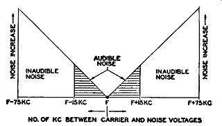
FIG. 3.7. Noise response of an FM receiver. The noise intensity increases
directly with frequency separation between carrier and interfering signal.
Now compare this situation with the corresponding AM case. To place AM and FM on a comparable basis we will assume that the full 15,000 cycles can be passed by the AM receiving networks. Each random voltage (of different frequency) will mix with the AM carrier to form a beat note. The amplitude of each note is the same because all random voltages have approximately the same strength. Thus, in place of the triangular response of Fig. 3. 7 we obtain the rectangular response shown in Fig. 3.8. This noise extends to 15 khz on either side of the carrier and then stops abruptly because of our aural limitations.
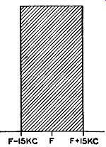
Fig. 3.8. The noise characteristic of an AM receiver.
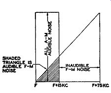
FIG. 3.9. A comparison between AM and FM noise characteristics. Note
that all the AM noise is audible, whereas only a small segment of the
total possible FM noise is effective.
In Fig. 3.9, half of each response curve is superimposed on the other to indicate the greater effectiveness of FM over AM. Only half the plots arc used because both halves of each curve are identical. A rough comparison readily indicates that the FM system gives less noise in the output. Just how much the difference actually is can be shown mathematically to be 18.75 decibels or an equivalent signal-to-noise voltage ratio of 8.65. In other words, because of intrinsic characteristics, an FM system is more effective against the ever-present noise interferences than the AM method of trans mission. All this, of course, in the presence of a carrier. Without the carrier, it has already been noted that the FM system is noisier.
Noise and the Deviation Ratio. The deviation ratio of an FM system has a direct bearing on its ability to suppress noise. By deviation ratio we mean the ratio of the maximum carrier swing to the highest audio frequency.
For the figures quoted previously, a deviation ratio of 5 was used; that is, a maximum carrier shift of 75 khz and an audio frequency of 15 khz.
Suppose, however, that the FM system is designed for a maximum frequency deviation of 60 khz. The highest audio frequency will be kept at 15 khz. The foregoing set of conditions limits the shifting of the carrier, under high level audio voltages, to 60 khz. At the receiver, with the same degree of noise present as before, we have less desired signal pushing through to override the noise. As a consequence, the signal to-noise ratio is lower and the ...
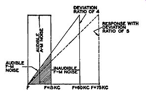
Fig. 3.10. The increase in noise in an FM receiver with decrease in
deviation ratio.
... effectiveness of FM has decreased. It is the ratio of the desired FM swing to the indirect FM swing produced by the interference that accounts for the efficacy of the system. For a deviation ratio of 4 (60 ..;- 15), the signal to-noise ratio reduces to 6.92, or a decibel value of 16.75. A comparison between this FM system and AM is shown in Fig. 3.10. It is quite evident that the effectiveness of the FM has diminished, as indicated by the larger proportion of the shaded triangle.
If we continue to limit the swing of the FM carrier, the signal-to-noise improvement (over AM) diminishes correspondingly. Comparison diagrams are shown in Fig. 3.11 for the instances where the FM shift is reduced to 45 khz, then 30 khz, and finally 15 khz. Note that even in the worst situation, with a total frequency shift of only 15 khz, we still obtain a better signal-to noise ratio than possible with AM. The advantage is 4.1875 decibels.
The importance of obtaining the highest deviation ratio is thus evident.
That the deviation ratio does not extend beyond 5 is due to the fact that the additional ether space required would permit less stations to be assigned operating licenses. If, for example, we permitted a deviation ratio of 7, then for a maximum audio-modulating frequency of 15 khz, we would need 105 khz on either side of the carrier. Add to this a 25- khz guardband and we have a total bandwidth of 260 khz. Since a deviation ratio of 5 has proved satisfactory, it has been established as standard.
Pre-Emphasis and De-Emphasis. In the analysis of many broadcast programs, it was found that most of the energy is contained at the lower audio frequencies. In addition, it has further been brought to light that the greatest irritating noise generated is located from 5000 cycles up. To reduce the effect of the noise, a pre-emphasis network is inserted in the audio section of the transmitter. The function of the circuit is to favor the frequencies above 1500 cycles. It accomplishes this by proportionately attenuating the lower frequencies more than the higher frequency components of the signals passing through the network.
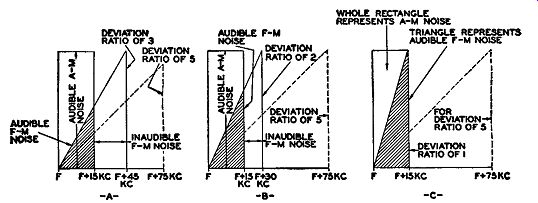
Fig. 3.11. Further comparisons between the noise in AM and FM systems
with various FM deviation ratios.
Pre-emphasis is applied to the audio signals at the first audio amplifier.
Beyond the pre-emphasis network, the audio voltages combine in the usual manner with whatever noise is present in the system. At the receiver there is a de-emphasis circuit with the reverse properties of the pre-emphasis circuit. The frequencies above 1500 cycles are reduced to their original values.
At the same time a similar reduction in noise occurs. The overall effect is a return of the signal to its proper relative proportions, but with a considerable reduction in noise.
A typical circuit which will favor the higher frequencies is shown in Fig. 3.12A. It consists of a resistor, R1 , and an inductance, L1.
The incoming audio signal, coming from a microphone, record player, or tape recorder, is made to pass through this network before it is applied to the audio amplifier.
R1 and L1 are in series and each applied voltage will divide between them in direct proportion to their impedances. L1, however, presents an impedance that increases with frequency (XL= 2wfL),. so that, as the signal frequency rises, more of its voltage will appear across L1 and less across R1. Since only the voltage that appears across L1 reaches V1, we can see that the higher frequencies will receive favored treatment.
A de-emphasis circuit is shown in Fig. 3.12B. The audio signal to be de emphasized is applied to the series combination of R1 and C1 . Again, this voltage will divide in direct proportion to the relative impedance of each component. C1 , however, presents a decreasing impedance with frequency (...) , so that the higher frequencies will develop less voltage here than the lower frequencies. If the pre-emphasis networks are properly designed, their effects will counterbalance and the original audio signal will appear at the receiver output.
Another beneficial effect of de-emphasis is concerned with the noise that is produced by another station or the ever-present random noise. As we have seen, the greater the difference between our carrier frequency and the interference, the greater the indirect FM formed (see Fig. 3.7). Through the use of the de-emphasis network, the triangular response of Fig. 3.7 is modified to that of Fig. 3.13. The de-emphasis action, by reducing the level of all frequencies above 1500 cycles, slices off a considerable portion of the noise.
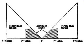
FIG. 3.13. Improvement in noise reduction due to pre-emphasis circuit
in transmitter.
IMPULSE NOISE
Impulse noise, as distinguished from random noise, consists of short, sharp bursts of energy caused by agencies, man-made or natural, external to the receiver. A very familiar example of such interference is the type of noise generated by auto-ignition systems or sparking in electrical machines. Al though the average value of these bursts is quite low, the peak value may exceed the signal and hence appear noticeably in the loudspeaker.
As long as the peaks exceed the signal, FM will be unable to override them. At best, all we can do is to minimize the effect of these peaks. For this purpose, the limiter stage can be very useful if designed to respond instantaneously to the rapidly recurrent pulses.
How this is accomplished will be made evident in Section 8.
HUM
Hum, in a receiver, may affect the desired signal at two points, in the radio-frequency stages and in the audio amplifiers. Hum, in the majority of instances, arises from insufficient filtering in the power supply, although any unshielded transformers and chokes in the power circuit may just as readily be the source, even if the final output from the unit is pure d-c.
Regarding the effect on the FM receiver output we find that the hum introduced by way of the audio amplifiers is the most annoying. Hum effect is negligible if arising in the R.F. or I.F. stages because the resulting amplitude modulation introduced is removed at the limiter and any phase modulation is generally exceedingly minute.
We must treat hum, present in the audio amplifiers, in exactly the same manner as we do in AM receivers. Once the FM signal has been converted to audio variations, it no longer has the protection of FM. Hence, anything that will affect its amplitude will be carried through to the loudspeaker.
Careful by-passing of all d-c connecting points is necessary, plus adequate shielding of transformers and chokes in the power supply. Filament or heater leads must be positioned as far away as possible from grid wires, plate leads and any other links in the audio channel that would affect the audio signal.
The methods are familiar to the radiomen who have encountered the same problem in AM sets.
EXAM
1. Name the most important types of interference that can affect radio reception and explain each briefly.
2. What is the cause of a beat-note whistle in an AM receiver? How is this eliminated in FM receivers?
3. Explain how phase and amplitude modulation arise from interference.
4. How does an FM receiver effectively deal with the phase and amplitude modulation produced through interference?
5. Of the phase and amplitude modulation produced through interference, which is the most troublesome to an FM receiver? Why?
6. In the expression, t::.F = f X t::.8, what does each symbol represent? Indicate the proper units for each symbol.
7. How much indirect FM is produced when two incoming signals differ in frequency by 5000 cycles and the maximum phase modulation produced is 60° ?
8. What are the advantages of wide-band FM as compared to narrow-band FM?
9. What effect does the frequency separation of the two interfering signals have on the amount of interference produced? Explain. For what frequency separation is the interference a minimum?
10. What is the significance of the 2 to 1 ratio in FM reception?
11. What factors limit the effect of interference in an FM receiver?
12. Can stations operating on adjacent channels interfere with each other? How?
13. What have the F.C.C. and the receiver manufacturers done to minimize interference arising from stations operating on near-by channels?
14. What is static? Why does it affect an FM receiver less than an AM receiver?
15. Under what general category can thermal agitation and tube hiss be placed? What is the frequency spectrum distribution for this type of noise?
16. "An FM receiver is noisier than an AM receiver." Explain under what conditions this statement is true.
17. Why is the noise characteristic of an FM receiver triangular whereas in an AM set it is rectangular?
18. What is the most difficult type of noise for an FM receiver to cope with? Why?
19. What is the relationship between the deviation ratio of an FM signal and its ability to suppress noise and interference?
20. When the deviation ratio of an FM signal is 1, is the FM system of modulation superior to AM modulation? Explain.
21. How does poor filtering in the power supply affect an FM receiver? How does this differ from its effect in an AM set?
22. Explain pre-emphasis and de-emphasis.
23. Why are pre-emphasis and de-emphasis beneficial to an FM receiver? Could the same networks be employed for AM transmission? Explain.
+++++++++++