Introduction. In this Section we shall discuss the manner by which the generated signal at the broadcast station is radiated and the means by which this signal is intercepted at the receiver.
The present allocations established by the Federal Communications Commission set aside the frequencies extending from 88 to 108 mhz for the trans mission of FM signals. Now, this band of frequencies is almost 70 times higher than the present standard AM broadcast band, and just as differences exist between AM and FM receivers because of the difference in operating frequency, so differences exist between low frequency and high frequency antenna systems. In order to understand why these differences exist, a general review of radio wave propagation will be undertaken.
An antenna is simply a wire or group of wires which is placed out in the open as far as possible from surrounding objects. Energy is fed to the antenna from the transmitter with the result that currents are established in the wires, flowing first in one direction and then in the other. The currents, in turn, establish magnetic fields which expand and contract about the wires in step with the periodic rise and fall of the rapidly alternating currents.
Now, if all the electromagnetic energy established by the antenna currents returned to the wires, no signal would be radiated. However, not all the energy is returned, and that portion which does not return represents the transmitted signal.
The purpose of the receiving antenna is to intercept some of this radiated energy, developing there from a voltage which is applied to the receiver terminals. Since the fields that the receiving antenna intercept are due to the transmitting antenna, we could quite logically state that the receiving antenna and the transmitting towers are coupled to each other. To be sure, the coupling is loose, because the two antenna systems are widely separated; but coupling exists. If we think back to our own experience with coupled coils in radio circuits, we know that maximum voltage is induced in the secondary coil when it is held in the same position as the primary coil. Minimum voltage is induced when the two are held at right angles to each other. By the same token, if the transmitter antenna wires are placed in a horizontal position, then the receiving antenna should be placed in the same relative position. Signals from antennas held in this position are said to be horizontally polarized. If desired, the antenna wires may be mounted vertically, in which case the electric component is said to be vertically polarized. Polarization of an antenna is important, as we shall see in the following discussion.
WAVE PROPAGATION
Types of Radio Waves. Radio waves radiated by an antenna system may follow one of two general paths to reach the receiver and are classified either as ground waves or sky waves, depending on the path that they travel.
Ground waves are those which either travel not far above the ground or else are actually guided by the ground. Sky waves are those which travel up ward away from the earth for distances sometimes as much as 250 miles before they are bent sufficiently to enable them to return to earth.
Although there is essentially only one mode for sky wave transmission, ground waves may be subclassified into surface waves, direct waves, and ground-reflected waves. Each of these subdivisions enters into the propagation picture in a different way. This will become clearer as we progress.
Surface Waves. Perhaps the best point at which to begin is the surface wave because propagation at low frequencies is accomplished principally through this medium. A surface wave is a wave which travels in contact with the ground, actually being guided by it. The wave must be vertically polarized because, to low and medium frequency voltages, the earth is a fairly good conductor, and a horizontally polarized wave would have the electric field parallel to the ground. The conducting earth would short-circuit the field, preventing its propagation for any appreciable distance.
The surface wave, as it moves over the surface of the earth, induces charges in the earth. The periodic change in wave polarity causes the charge concentration to vary from point to point. These concentrations can vary only by having electrons flow from point to point, and this, in turn, constitutes a current. Since the earth possesses resistance, forcing current to flow through it results in a power loss, the power being supplied by the trans mitted wave. As the frequency of the signal increases, the amount of power that is lost rises until, at about 2 mhz, the coverage obtained by means of the surface wave is confined to very short distances. However, surface propagation in this manner is extremely useful at lower frequencies. Ship-to shore installations operating below 500 khz use enormous antennas but are capable of transmitting steady signals for distances of 1000 miles or more with unvarying regularity. At the AM broadcast frequencies, 550 to 1600 khz, the primary and secondary service areas receive their signals almost entirely by the surface wave.
The other divisions of the ground wave, the direct ray and the earth reflected ray, do not become important until the signal frequencies rise above 30 mhz. Long-distance communication between 2 mhz and 30 mhz is accomplished principally by the sky wave.
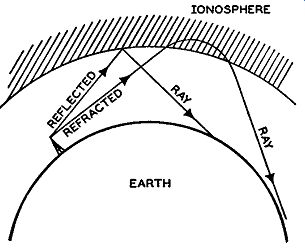
FIG. 4.1. Illustration of reflection and refraction of radio waves at
the ionosphere. Reflection occurs less frequently than refraction.
Sky Wave-Ionosphere. The energy radiated by an antenna which does not follow the contour of the earth travels upward through the air until it reaches a region where there exists a concentration of ions and electrons.
This region is the ionosphere. For those who are unfamiliar with this terminology, ionization is the process of separating a molecule (in this in stance a gas molecule) into a positive ion and one or more electrons. Molecules, of their own accord, seldom separate in this manner. However, by the application of sufficient energy from some outside source, separation can be achieved. In the ionosphere ultra-violet radiations from the sun arc this source of energy.
These rays, penetrating the gaseous layers surrounding the earth, supply enough energy to cause the electrons to separate from their molecules, the result being a concentration of negative electrons and positively charged ions. Radio waves traveling up from the antenna enter this ionized region and, by the interaction of the wave energy and the free electrons, are bent back toward earth. This process is essentially one of refraction, similar to the effect prisms have on light rays. However, reflection from the ionosphere also occurs, although to a considerably smaller extent. Both methods are illustrated in Fig. 4.1.
The layers of ions, or ionosphere as they are collectively called, are found at distances of from 70 to 250 miles above the surface of the earth. Analysis of this region has disclosed that, although there is ionization of the gas molecules throughout the entire area, there are distinct layers in which the ion concentrations rise to a maximum. The layers are distinguishable and have been given specific designations. The lowest layer, called the E layer, is found about 70 miles above the earth, and this height is fairly constant.
The next region of maximum ion concentration occurs at a distance of about 185 miles above the earth. This layer has been labeled the F layer, but it exists as one layer only at night, after sunset. During the day it separates into two distinct groups of ions, labeled F1 and F2 , respectively. The F1 layer is usually found 140 miles above the ground while the F2 layer forms at about 225 to 250 miles. At night, of course, the two regions combine again to form the single F ionized layer. The three are shown in Fig. 4.2 together with the lower E layer. The F2 layer has the greatest degree of ionization and electron density. It is the layer that refracts the radio waves of higher frequency, the waves that other layers cannot turn back. If a wave does not receive sufficient bending in this final (F2) layer, it continues into empty space.
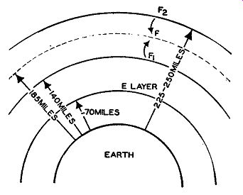
Fig. 4.2. The various layers of the ionosphere. The distances shown
are only approximate values since the exact heights vary from day to
day.
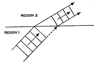
Fig. 4.3. Refraction of radio waves entering the ionosphere.
Wave Bending. When a radio wave enters the ionosphere, the electric field of the wave acts on the charged ions and electrons, causing them to vibrate in accordance with the changes occurring in the electric field. The important vibrations arc those of the electrons since they have a mass which is roughly 1800 times less than the ions, and there fore they are capable of executing greater vibrations than the ions.
The frequency of these vibrations are the same as the frequency of the wave. Since moving electrons constitute an electrical current, we have, in effect, a large number of minute antennas, each radiating a signal having a frequency equal to the frequency of the arriving wave. At the start, when the electric field of the radio wave acts on an electron, the result is a vibratory motion which is parallel to the electric field. However, once the electron starts to move, it reacts with the earth's magnetic field, causing it to leave its straight line path and to travel a more or less spiral path. The energy that is radiated by the electron has now changed direction. In the conditions existing in the ionosphere, this change in direction is such that the energy is reradiated partially or wholly toward the earth. We obtain the same effect as though the arriving radio wave had been bent around as in Fig. 4.3. The process of bending the radio wave is known as refraction.
The degree of bending that a wave receives depends primarily upon three factors: the angle at which the wave enters the ionosphere, the frequency of the wave, and the electron density of the layer. The importance of the angle may best be seen by reference to Fig. 4.4. The greater the angle <f,, the more the wave has to be bent, or refracted, in order that it return to earth. Waves entering at very small angles require only a slight amount of bending to have their direction changed sufficiently to cause them to return to earth again.
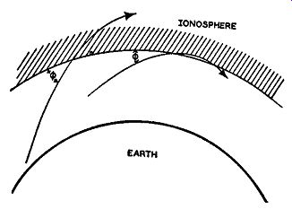
Fig. 4.4. As the angle q, which the radio wave makes with the ionosphere
increases, more bending must occur before the radio wave is bent back
to earth.
The frequency of the wave is important because it determines the type (and length) of the path followed by the vibrating electron.
When the frequency is high, the electron direction must reverse it self so rapidly that the electron never achieves a very high velocity.
Its interaction, then, with the earth's magnetic field is correspondingly slight, resulting in only a small change in electron path. Consequently, the energy reradiated by the electron does not differ appreciably in path direction from that followed by the original wave. However, as the frequency decreases, the velocity of the electron increases because the time between reversals is greater. Its path now is more truly spiral, and the electron direction is altered more by the earth's magnetic field. The reradiated energy thus shows a greater bending effect.
Finally, the density of the charged particles in the layers themselves will determine, in the final analysis, just how much the wave is bent. As the density increases, the amount of refraction increases for any one wave.
Critical Frequencies of Ionosphere. Radio waves may be sent upward at almost any desired angle, but the wave that will require the greatest amount of bending is one that is sent vertically upward or, what is the same thing, at right angles to the earth's surface. The frequency of the wave that is bent back after entering a certain layer at that vertical angle is known as the critical frequency for that particular layer. If a wave of high frequency enters this ionosphere layer at right angles, it will usually not be refracted enough to make it return to earth and will continue upward. How-ever, this wave of higher frequency may enter the ionosphere at a smaller angle, say 50°, and have a better chance of being returned to earth. Of course, if the frequency is very high, not even a small angle of incidence will help, the wave in this case continuing out into space. At various times in the day and during the year the density of a given layer will change, where upon its critical frequency changes. Should the density increase, the critical frequency value would rise. Should the density decrease, it would be necessary to lower the critical frequency. The critical frequency may thus be looked upon as an index of the ability of the ionosphere to return a wave to earth. All lower frequencies will be refracted to earth no matter what the angle used to transmit them upward, whereas higher frequencies may be re turned only if the proper angle is used. The lowest angles achievable in practice are about 4° to 6° with the horizon. If a wave cannot be returned at this elevation, sky wave transmission cannot be used for this particular wave length.
Sporadic E. The discussion thus far has confined itself to what might be called normal conditions. Under these circumstances, frequencies as high as 30 to 35 mhz can regularly be refracted by the F2 layer. For frequencies beyond 35 mhz, sky wave transmission becomes useless, the waves receiving insufficient bending to return to earth. However, every once in a while it is found that frequencies as high as 60 mhz are refracted back to earth by the ionosphere. As this is an unusual occurrence, it is necessary to look for conditions in the ionosphere that are present only at these times and then disappear. Investigation has revealed that at these times portions of the lower E layer contain unusual concentrations of electrons, and it is these patches which refract the higher frequencies. The name given to these small, well defined regions within the E layer is Sporadic E spots. These spots occur rather frequently, especially in summer, and are used to good advantage by the amateurs operating on the 56 -mhz band. They may last from a few minutes to many hours and may remain in one locality or travel about at high speeds. The time of the day or night does not appear to have too great a bearing on their appearance since long-distance communications have occurred at all times.
Another phenomenon that occurs frequently is the intense magnetic "storm" that disturbs long-distance communications for periods of from 3 to 5 days. During these storms the earth's magnetic field fluctuates widely in intensity and then gradually settles down to its normal value. The origin of these storms appears to be in the sun where certain types of solar disturbances cause the emission of clouds of electrons and other charged particles.
These particles travel from the sun to the earth, penetrating through the F layers and reaching the E layer. The effect of these clouds of charged particles on our own ionosphere depends on their intensity and the extent of the clouds. Under a severe invasion, the layers of the ionosphere lose their distinctiveness, varying widely in density, height, and refractive power. The F2 layer may even disappear for a short time. Long-distance communication during these periods of turbulence is erratic.
The terms "reflection" and "refraction" have been previously illustrated (Fig. 4.1), and it is seen that when a wave is reflected from a surface its direction is sharply altered whereas when a wave is refracted, the change in direction occurs gradually. Most wave-bending in the ionosphere is achieved by refraction. However, when the frequency of the signal is sufficiently low, and the ionized layer sufficiently dense, the wave does not penetrate the layer to any appreciable extent, and change in direction occurs through reflection.
The line of demarcation between reflection and refraction is not too distinct, and throughout the literature both terms are used interchangeably, especially when describing the phenomenon that occurs during periods of ionospheric disturbances.
H.F. Propagation. The discussion, thus far, has concerned itself exclusively with radio communication using frequencies up to approximately 30 to 35 mhz. These are the highest frequencies that will be refracted by the F2 layer under what may be termed normal conditions. For Sporadic E refractions it is possible to go as high as 60 mhz although odd conditions are encountered. While Sporadic E refractions occur quite frequently, they can not be depended upon for any regularly scheduled traffic. From here to the end of this Section, frequencies in the very high region will be emphasized, extending beyond 30 mhz.
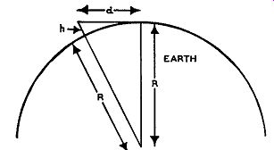
Fig. 4.5. How to calculate the line of sight distance.
Three Components of H.F. Propagation. High frequency wave propagation can be broken down into three categories, each of which is responsible for the reception of these signals by a ..._c1.~ different means. First is the so-called "line-of-sight" method which embodies both a direct ray and an earth reflected ray; second, there is refraction in the region of the troposphere; and last, there is diffraction around the curvature of the earth. These three methods are generally independent of each other. Although it may happen that all of these methods combine to lay down the same transmitted signal at the same point, it does not occur often. Usually the last two modes of propagation are responsible for signals appearing beyond the horizon, whereas the first method deals with the distances such that the receiving and transmitting antennas are in a direct line above the curvature of the earth.
Line-of-Sight Method. In this method of wave propagation, energy from the transmitting towers travels on a direct line to the horizon. Beyond the horizon, an extension of the straight line from the transmitter shows that the energy travels into the ionosphere and on into outer space. Unless this energy is intercepted by a receiving antenna before it travels away from the earth, communication by this method becomes impossible.
The following simple derivation will indicate how to determine the distance from the transmitting tower to the horizon. To simplify the mathematics, it will be assumed that the earth is flat over that small portion of its surface. This assumption results in a right triangle. (See Fig. 4.5.) From elementary geometry it is possible to write the following equation: d2
+ R2
= (R + h) 2
= R2
+ 2Rh + h2
Since h is very small compared to the radius of the earth, the h2 term can be neglected. This gives us d2
+ R2
= R2
+ 2Rh or d2
= 2Rh
In this equation, R is most conveniently stated in miles, h is best given in feet. In order for d to be given in miles, h must be divided by 5280 to convert to miles and keep the units on both sides of the equation identical. The equation now becomes 2Rh a 2
= 5280
The radius of the earth is approximately 4000 miles. If we substitute this value in the above equation, we obtain d = 1.23\!h where d is in miles and h is in feet. To show the relationship between d and h for various values of h, a graph of the equation has been drawn and is shown in Fig. 4.6.
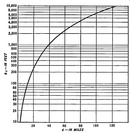
FIG. 4.6. The relationship between the height of the transmitting antenna
(in feet) and the distance in miles from the antenna that the ray may
be received.
FIG. 4.7. Increasing the line-of-sight distance from the receiving antenna to the transmitter by raising both structures as high as possible.
It is assumed in the foregoing that the receiving point is at ground level, and the result indicates the distance from the transmitting antenna to the horizon. However, if the receiving antenna is not at ground level but is raised into the air, it should be evident that the direct-line distance between the two antennas can be made greater before the curvature of the earth again interferes with the direct line. (See Fig. 4.7.) By means of simple geometrical reasoning, the maximum distance between the two antennas is now in creased to
d = 1.23(\!ht + yh,)
where d is the distance between antennas in miles, h1 is the transmitting antenna height in feet, and hr is the receiving antenna height in feet. Be cause raising the antenna height increases the direct-line distance, transmitting antennas for FM and television stations are placed atop tall buildings or on high plateaus. There may be other obstacles in the path of the direct rays which would result in absorption of the signal energy and hence tend to weaken or distort the received sound or picture. These obstacles assume great importance for television stations where the interfering influences may result in distorted images on the cathode-ray tube screen.
The signal developed at the receiving antenna is due not only to the direct ray but, in addition, to a ground reflected ray. In Fig. 4.8, the waves reaching the receiving antenna may do so by one of two paths: by going directly to the receiving antenna; or by arriving there after reflection from the surface of the earth. Whether or not a good clear signal will be received depends upon the phase relationship of the combining signals. To illustrate this point further, note what happens to the reflected wave. At the point where the reflected ray impinges on the earth, a phase reversal of 180° and, in addition, an absorption of energy in an amount dependent upon the conductivity of the earth at this point have been found to take place. The phase shift produces a wave at the receiving antenna which acts in a manner opposite to the direct ray, lowering its signal level. Fortunately, two conditions act against this de crease by the reflected ray. One is a weakening of the wave due to absorption at the point where the wave grazed the earth; the other results from an additional phase change (not the 180° just mentioned) arising from the fact that the length of the path of the reflected ray is longer than that of the direct ray. Thus, there is a total phase shift of 180° plus whatever else may have been added because of the longer path. As a result of these factors, the strength of the direct signal is not decreased as much by the reflected wave as one would at first expect. It has been found that the received signal strength increases with height of both antennas. At the same time, a decrease in noise pick-up occurs. For FM and television signals this decrease is most important. By raising both antennas, we can increase the difference between the lengths of the paths that the direct and earth reflected rays travel and thus bring their phase difference closer to 360°. When a phase difference of 360° occurs be tween the signals, they add, producing a field strength which is approximately twice that obtainable from the direct wave alone. In general, the higher the antenna, the stronger the signal received.

Fig. 4.8. The reflected radio wave, arriving at the receiving antenna
after reflection from the earth, may lower the strength of the direct
ray considerably.
The combination of a direct wave and an earth reflected ray is sometimes referred to in the literature as a space wave. It is not important in AM broadcasting because the relatively long wave lengths used make the difference in paths between the two rays negligible. The waves are then nearly 180° out of phase because of the phase reversal in the earth reflected ray, and they effectively cancel each other completely. Hence, only the surface wave is important. However, as the signal frequency increases, and the wave length decreases, path differences between the direct and earth reflected ray become more significant. At the same time, the effect of the surface wave diminishes.
Vertical Versus Horizontal Antennas. The relative merits of vertical versus horizontal polarization have been intensively studied, and it has been found that for antennas located close to the earth the vertically polarized rays yield a stronger signal. Upon raising the receiving antennas about one wave length above the ground, both types of polarization are equally good.
Further increase up to several wave lengths has shown that the horizontally polarized waves find a more favorable signal-to-noise ratio and are therefore to be desired. Hence all FM transmissions are done with horizontally polarized waves.
If signals were received only in accordance with the foregoing formulas and reasoning, the study of ultra-high frequency propagation would have ended there. But signals were consistently received at points beyond the horizon in usable quantity and evidently not due to any unusual phenomena.
The reasons for these added field strengths are laid to two definite causes: refraction in the lower atmospheric regions and diffraction by the surface of the earth at the horizon.
These two effects tend to increase the range of an FM signal for some distance beyond the horizon. A good approximation of the actual distance covered is to modify the line-of-sight equations by a factor of 1.41 instead of 1.23. Thus the previous equation of d = 1.23\jh and d = 1.23(yh1 + yh,) become d = 1.41yh and d = 1.41 (\Jhi + yh,)
With this understanding of the behavior of high frequency waves in the FM band, we are in a position to appreciate better the reasons for the choice of receiving and transmitting systems.
Receiving Antennas. The primary purpose of an FM receiving antenna is to develop as much voltage as possible of the desired signal. Now, the amount of voltage which the passing field induces in an antenna wire depends essentially upon two factors: ( 1) the manner in which the wire is held; and (2) the length of the wire. Technically, (1) is referred to as the polarization of the wire and (2) as its resonant frequency. The first factor, polarization, has already been considered, and it was seen that both receiving and transmitting wires should have similar polarization. In FM reception, this means horizontal polarization.
The second factor that governs the amplitude of the induced voltage is the resonant length of the receiving antenna. Every length of wire contains resistance, inductance, and capacitance. The longer the wire, the greater the inductance. The capacitance of an antenna is the capacitance formed between the various sections of the wire itself. (see Fig. 4.9.)
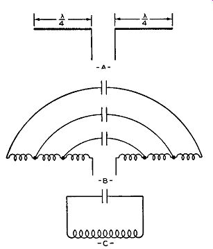
FIG. 4.9. (A) A half-wave dipole antenna. (B) The actual inductance
and capacitance in the antenna wires. (C) The equivalent conventional
L-C-circuit.
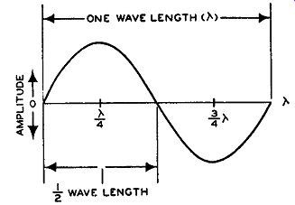
FIG. 4.10. The wave length of an electromagnetic wave.
The resonant frequency of the antenna depends upon its inductance and capacitance just as it does in any conventional tank circuit. Since inductance (which predominates) increases with antenna length, increasing the length of the antenna decreases its resonant frequency. By the same token decreasing the antenna length in creases its frequency. If the wave length of the received wave is known, it becomes a simple matter to compute the required length of the line. Thus, an antenna is similar to a resonant tank circuit, and its resonant frequency will vary with its length.
Tuned circuits are more sensitive to signals at their resonant frequency than at any other frequency. Hence, antennas designed for FM are cut to specific lengths. The extent of the FM band is 20 mhz, and the antenna should be capable of receiving all frequencies within this band with equal response. However, whether a single frequency is to be received or a band of frequencies, a tuned antenna still provides the best results. In the case of a band of frequencies a compromise frequency is chosen generally at the center of the band and the antenna made resonant to it.
Wave Length. The distance covered by 360° of an electromagnetic wave is called one wave length and this is designated by the symbol A (lambda). (See Fig. 4.10.) A wave length is equal to the velocity of travel of the wave divided by its frequency. Thus, V A= f where A= the wave length in feet
V = the velocity in feet per second f = the frequency of the wave in cycles per second
We can use 984,000,000 feet per second for the quantity V because the velocity of the electromagnetic wave is the same as light. Hence the foregoing formula becomes 984,000,000 A
-----
The use of the formula is illustrated by the following example:
EXAMPLE: What is the wavelength of a 90 -mhz wave?
Answer: 984,000,000 A= 90,000,000
A= 10.9 feet
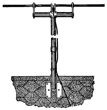
Fig. 4.11. Dipole antenna assembly used extensively for television receivers.
Half-wave Antennas. An ungrounded wire, cut to one-half the wave length of the signal to be received, represents the smallest length of wire that can be made to resonate at that frequency. The half-wave length antenna is most widely used because it is small, compact, and usually provides the receiver with sufficient signal. In troublesome areas it may be necessary to erect more elaborate arrays possessing greater gain and directivity than the simple half-wave antenna. They are, however, more costly and more difficult to install.
A simple half-wave antenna is erected and supported as indicated in Fig. 4.11. Metallic rods are used for the antenna itself, mounted on the supporting structure and placed in a horizontal position (parallel to the ground). Each of the rods is one-quarter of a wave length long, both together being equal to the necessary half wave length. In this arrangement, also known as a dipole antenna, the transmission lead-in wire is connected to the rods, one wire of the line to each rod. The line then extends to the receiver. Care must be taken to tape the line at several points to the supporting mast so that it does not interfere with the operation of the antenna. Taping also prevents the line from flapping back and forth in the wind. Any such motion could weaken the connections made at the rods.
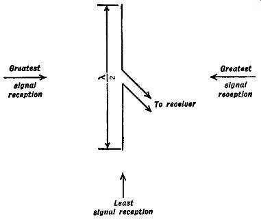
FIG. 4.12A. Dipole antenna, of the type shown, receives signals best
from the directions indicated.
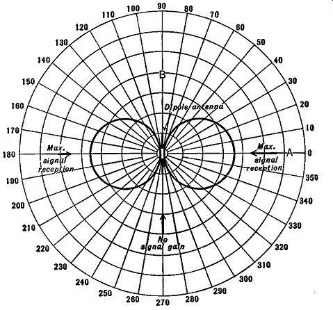
Fig. 4.12B. The directional response curve of a dipole antenna.
When the properties of a dipole antenna are investigated, it is found that signals are received with greatest intensity when the rods are at right angles to the direction of the signal. This is illustrated in Fig. 4.12A. However, signals approaching the antenna from either end are very poorly received.
To show how waves at any angle are received, the graph of Fig. 4.12B is commonly drawn. It is an overall response curve for a dipole antenna.
From the diagram, with the placement of the antenna as shown, the strongest signal would be received from direction A. As the angle made with this point is increased, the strength of the signal voltage decreases, until at point B (90°) the received signal voltage is at a minimum (or zero). The reader can determine the reception for waves coming in at other angles by inspection of the graph. Notice that good signal strength is obtained from two directions and, because of this, the dipole response may be called bi directional. Other systems can be devised that are uni-directional, non directional, or having almost any desired properties. For each system, a response curve would quickly indicate its properties in any direction.
As stated, an antenna must be tuned in order to have the strongest signal develop along its length. Hence it becomes necessary to cut the wire ( or rods) to a specific length. The length will vary with each different frequency, longer at the lower frequencies, and shorter at the higher frequencies. It might be supposed, then, that an FM set, capable of receiving signals with frequencies ranging from 88 to 108 mhz, would need several antennas. It is not necessary, however, to go to such extremes and, in nearly all instances, one antenna is sufficient, if tuned to a middle frequency.
Antenna Length Computations. With the FM range of frequencies, a middle value of 98 mhz might be chosen. Although an antenna cut to this frequency would not give optimum results at the extreme ends of the band, the reception would still be satisfactory.
To compute the length needed for the 98 -mhz frequency half-wave antenna, the following formula is used:
Lr...,t = -
468 / fm<'
With f set equal to 98 mhz, the length would be equal to 468/98, or 4.7 feet.
Practically, 5 feet might be cut, with each half of the half-wave antenna 2.5 feet long. For a full-wave length antenna, approximately 10 feet is needed. In congested areas, antenna length must be as short as possible, and only half-wave antenna systems are generally found. If longer lengths are desired, the equation should be modified by the proper factor. A full wavelength antenna requires a factor of 2; a wave length and a half re quires a factor of 3, etc.
A little thought will show that a half-wave dipole, no matter in what position it is placed, will always radiate a maximum amount of energy at right angles to the wire axis. When the wire is held vertically, right angles to the wire is the horizontal plane and since this plane exists at all points around the wire, the radiation pattern is non-directional. However, when the wire is laid on its side or held horizontally, there are only two points in the horizontal plane that are at right angles to the wire. All other points in the horizontal plane make an angle of less than 90° with the wire, and the energy radiated in that direction varies accordingly.
If we were to illustrate the complete radiation pattern of a half-wave antenna in all directions, the radiation pattern would possess a doughnut shape. (See Fig. 4.13.)

Fig. 4.13. (A) The doughnut-shaped pattern of a vertically placed dipole.
(B) A cross section of the doughnut pattern. (C) A cross section when
the antenna is horizontal. Compare (C) with Fig. 4.12B.
Connection to a half-wave dipole is made at its center terminals. The two conductors at one end of a transmission line connect here, as shown in Fig. 4.14, while the other end of the transmission line is connected to the input terminals of the receiver. The impedance which is present across the two antenna terminals is 72 ohms and, for maximum transfer of energy from the antenna to the transmission line, the impedance of the line should also be 72 ohms. (The various types of transmission lines suitable for this purpose will be indicated presently. At that time, the significance of impedance matching will also be covered.)
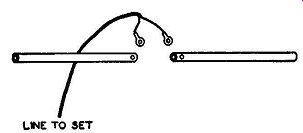
Fig. 4.14. How the transmission line is connected to the dipole antenna.
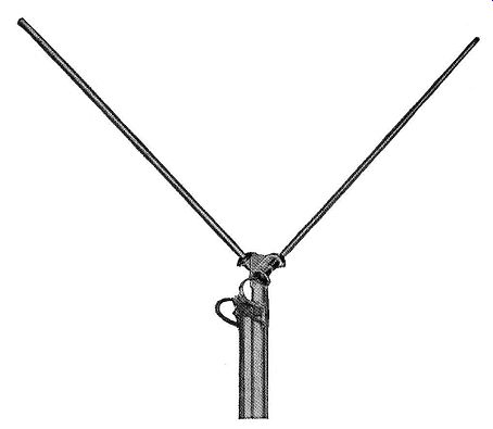
Fig. 4.15. The "V" antenna.
A variation of the dipole is the "V" antenna shown in Fig. 4.15. Actually, this antenna is simply a half-wave dipole whose two arms are bent at an angle to each other. FM transmitters emit horizontally polarized waves.
However, near the receiving antenna, because of reflections from tall trees, buildings, and other obstructions, there may be a vertical component which, when combined with the horizontal component, will alter the angle of polarization above the horizontal plane. Under these conditions, dipole antennas possessing the shape shown will receive the signals better than an antenna whose elements are perfectly horizontal. In the "V" antenna, the angle be tween the elements is adjustable over a wide range.
In strong signal areas, where roof antennas are either prohibited or impractical, an under-the-rug antenna of the type shown in Fig. 4.16 may prove useful. The antenna is stretched out on the floor and its transmission line attached to the receiver. The unit is then moved about until a good clear signal is obtained. At this point, the antenna is placed underneath the floor.
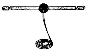
Fig. 4.16. An "under-the-rug" antenna.
Half-wave Dipole with Reflector. The simple half-wave system provides satisfactory reception in most locations within reasonable distances of the transmitter. However, the signals reaching receivers situated in outlying areas are correspondingly weaker, and noise and interference have a greater distorting effect on the sound. For these locations more elaborate arrays must be constructed-systems that can develop more voltage and provide better discrimination against interference.
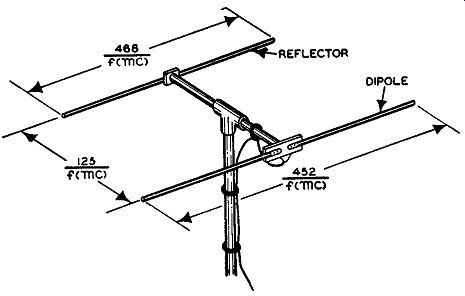
Fig. 4.17. A half-wave dipole and reflector. The length of each element
and the spacing between them is given also.
A simple yet effective antenna is shown in Fig. 4.17. The two rods are mounted parallel to each other, cut to the dimensions indicated by the formula, and spaced as shown. The action of the second rod (the reflector), which is not connected to anything, is twofold. First, because of its position, it tends to concentrate signals reaching the front wire. Second, it acts to shield the front rod from waves coming from the rear. The signal voltage developed by this antenna is generally 5 db greater than that obtainable from a single half-wave antenna.
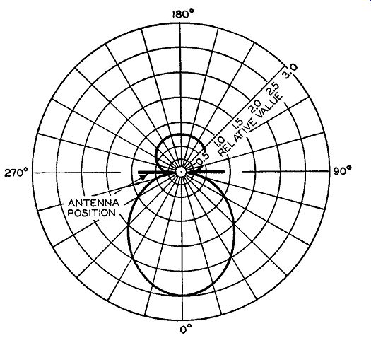
Fig. 4.18. The response characteristic of a dipole antenna with reflector.
The reflector, not shown, would be placed behind the dipole, facing 180°.
The response curve of a half-wave dipole and reflector is shown in Fig. 4.18. While not all of the signals reaching the antenna from the rear are suppressed, they are diminished sufficiently to render the response of the array essentially uni-directional. This is advantageous in reducing the number of reflected rays that can affect the antenna. Finally, partial or complete discrimination is possible against interference, man-made or otherwise.
The method of erecting the antenna is similar to that of the half-wave dipole, although the adjustment of the position of the wires is more critical.
A small displacement, one way or another, may alter the strength of the received signal appreciably. Many commercial antenna kits do not provide adjustment of the spacing distance between the two wires. However, if an adjustment is possible the spacing may be changed if experimentation indicates that it would result in better reception.
Gain. The gain of an array is a comparison of the signal power which this array would develop across its input terminals to the power which a standard or reference antenna would produce if placed at the same point in space as the directional array. The standard or reference antenna frequently chosen is the half-wave dipole.
Thus, when a certain array is said to possess a gain of 10, it means that this array will develop 10 times as much signal power as a half-wave dipole if it were positioned at the same point in space.
Often, the decibel is used as the unit of gain. In this case, since power is being employed, the formula is:
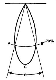
Fig. 4.19. The beam angle 8 of an antenna is the angle between two points
on its response curve at which the signal voltage is 70.7% of its maximum
value.
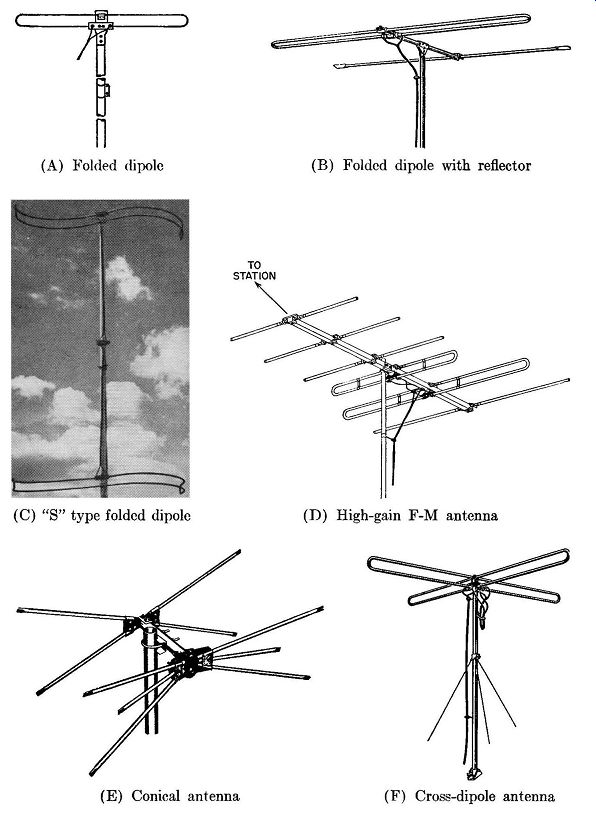
Fig. 4.20. Other popular FM antennas. (A) Folded dipole (B) Folded dipole
with reflector (C) "S" type
folded dipole (D) High-gain FM antenna (E) Conical antenna (F) Cross-dipole
antenna
A ratio of P1 and P2 of 100 would give the equivalent decibel rating of 20. This follows from that fact that the log_10 100 = 2, and 2 X 10 equals 20 db.
Directivity. When speaking of the directivity of a directional antenna, we mean the sharpness with which the signal is confined or directed to a particular direction. It may, in a sense, be compared with the selectivity of a receiver in allowing one signal to pass through and rejecting all others. The more selective the set, the sharper and more peaked its tuning curve.
In radio sets, sharp selectivity can usually be attained only when several tuning circuits are used in conjunction with each other. One coil and capacitor combination, by itself, would not be adequate. It is much the same with antennas.
Ordinarily several radiators must be used before a highly directive pattern is obtained. Just one or two elements, by themselves, might show definite directive effects, but these would not be as clear-cut as those obtained when a greater number of antennas are used. Again if a system of wires possesses a marked directional pattern for sending, the same antenna will show similar directivity when receiving.
When speaking of antenna directivity, the term "beam angle" is often employed. Beam angle is the angle between the two points on the radiation curve at which the signal voltage is 0.707 (or 70.7%) of its maximum value. In Fig. 4.19, the angle between points A-B, or the angle 8, is the beam angle for this radiation pattern. At each of these points (A and B), the signal strength is 0.707 of its value at point C. Points A and B are also known as the half-power points because the radiated power here is one-half of its value at point C. This is an equivalent expression because power is proportional to the square of the voltage and (0.707) 2 is approximately equal to 0.5.
Other Receiving Antennas. The two antenna systems described are the most widely used. Other types are found, however, and the more popular of these are shown in Fig. 4.20.
1. Folded Dipole, Fig. 4.20A. This consists of two dipole antennas connected in parallel, each dipole being a half wave length long. The separation between the two sections is approximately 3 inches. The folded dipole has the same bi-directional pattern as the simple dipole. Its gain, however, is somewhat greater.
2. Folded Dipole with Reflector, Fig. 4.20B. The addition of a reflector has the same effect here as with the simple dipole. Reflector spacing and length are identical with the figures previously given for the simple dipole with reflector.
3. "S" Type Folded Dipole, Fig. 4.20C. This array uses the basic folded dipole, but by twisting the elements into the position shown, essentially omni-directional reception can be achieved. The input impedance and gain of this array is similar to that of the folded dipole.
4. High-Gain Antenna, Fig. 4.20D. There are two folded dipoles, one rear reflector and three directors in this array. These provide considerably more gain than a folded dipole. However, the antenna has a very narrow directivity pattern and, therefore, must be oriented accurately in the direction of the FM stations.
One of the folded dipoles is tuned to the high end of the FM band and one dipole is resonated to the low end. The combination, interconnected, provides a fairly even response over the entire band.
5. The Conical Antenna, Fig. 4.20E. Contains two or three rods on each side of the feed point. This serves to broaden the frequency response. Has basically the same directional pattern as the dipole. Each rod is one-quarter wave length long.
6. The Cross-dipole Antenna, Fig. 4.20F. When signals come from widely separated directions, it may be desirable to have a non-directional antenna. This is true of the unit shown in Fig. 4.20F and consists of two folded dipoles set at right angles to each other. A quarter-wave section (at the operating frequency of the antenna) of a twin-lead transmission line having a characteristic impedance of 300 ohms is then connected between the input terminals of the two dipoles. To transfer the signal from the dipoles to the receiver, a transmission line is connected from one of the dipoles to the FM receiver.
After the particular antenna has been chosen, the following points should be kept in mind before installing the antenna.
1. The higher the antenna, the stronger the signal received.
2. The antenna should be set-tested with an actual connection to its receiver before the supports are fixed in place permanently.
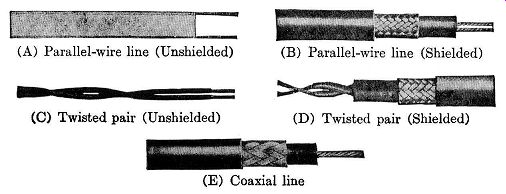
Fig. 4.21. Various types of popular transmission lines used for FM and
television installation. (A) Parallel-wire line (Unshielded) (C) Twisted
pair (Unshielded) (D) Twisted pair (Shielded) (E) Coaxial line
Transmission Lines. With the antenna system in position the next problem is the transmission line that conducts the signal from the antenna to the receiver. Although many differently constructed transmission lines have been designed, only five types find any extensive use in FM installations.
These are the two parallel-wire types, the concentric or coaxial cable, and the twisted pair.
Probably the most popular transmission line is the parallel-wire trans mission line shown in Fig. 4.21A. It is popular because its cost is relatively low, it is easy to work with, and it possesses a low attenuation. Physically, the two wires of this transmission line are encased in a polyethylene strip which serves to hold the wires in place and act as a protective covering. It has excellent electrical and physical characteristics, being a flexible material that is not affected by sunlight, water, cold, or alkalies. At 50 mhz, the line loss is less than 0.8 db per hundred feet of line. Its characteristic impedance ranges from 75 to 300 ohms and will match a folded dipole antenna. The line is balanced, which means that both wires possess the same average potential with respect to ground. It is, however, unshielded and therefore not recommended for use in locations where extraneous electrical signals are present.
A parallel-wire transmission line that is completely shielded is shown in Fig. 4.21B. The two wires are enclosed in a dielectric, possibly poly ethylene, and then the entire unit is shielded by a copper braid covering.
As a protection from the elements, an outer rubber covering is used. Grounding the copper braid converts it into a shield which prevents any stray interference from reaching either conductor. Furthermore, the line is balanced against ground. It is built with impedance values ranging from 95 to 300 ohms. The line loss is greater than the unshielded parallel pair, being on the order of 2.5 db per hundred feet at 50 mhz.
The twisted pair of transmission line, Fig. 4.21C, is made by twisting wires about each other in the same manner as twisted lamp cord. It is an economical line, but it has the greatest loss and becomes impractical for lengths beyond 50 feet. The characteristic impedance ranges from 50 to 150 ohms and, at 50 mhz, the db loss is 4 for each hundred feet of line. Unless this line is specially constructed, it will deteriorate in time under the ravagct5 of the atmosphere. A shielded twisted pair line is shown in Fig. 4.21D. This line has more desirable characteristics than the unshielded twisted pair, but its cost is greater.
The transmission line shown in Fig. 4.21E is the coaxial or concentric cable. It consists of insulated center wire enclosed by a concentric metallic covering, which is, generally, flexible copper braid. The inner wire is held in position by a solid dielectric, which is chosen for its low-loss properties.
The signal carried by the line is confined to the inner conductor, with the outer copper-braid conductor grounded so as to serve as a shield against stray magnetic fields. Because of this arrangement, the line is unbalanced and the input coil of the receiver must be connected accordingly. Coaxial cables are available in a range of impedances from 10 to 150 ohms .
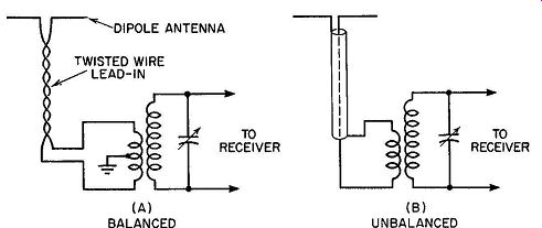
FIG. 4.22. Methods of connecting lead-in wires to the input coil of
a receiver.
At the receiver, the connections for balanced and unbalanced line differ, as shown in Fig. 4.22. For a balanced line, the input coil is center-tapped and grounded at this tap. Stray fields, cutting across both wires of a balanced line, induce equal voltages in each line. The similar currents that flow because of the induced voltages are in the same direction on the two conductors of the line and they neutralize each other. In the unbalanced line, the outer conductor of the coaxial cable is grounded, thereby shielding the inner conductor from interference.
Impedance Matching. At two points in the antenna system, connections must be made to the transmission line. One point is at the antenna, and the other is at the receiver input. For the maximum transfer of power, the antenna impedance should match the transmission line impedance, and a similar matching of impedances should occur at the receiver input.
The input impedance of most FM receivers is about 300 ohms. To match this, a 300-ohm parallel-wire previously discussed would serve nicely. At the antenna, a match to the 300-ohm line could be made by using a folded dipole antenna. Thus there is a matching of impedances at all connecting points in the antenna system, providing assurance of a maximum transfer of power.
Although this situation is fairly common, it does not represent, however, every type of installation that will be encountered. Suppose that, in the preceding example, the antenna is a dipole with an input impedance of 72 ohms. What would be the effect of connecting the 300-ohm line directly to the antenna? The answer to this question will depend upon the strength of the signals present in this particular area. If the signal intensity is of the order of 100 microvolts or more, then it is doubtful if the mismatch will have any noticeable effect upon the receiver output. True, a certain amount of the signal will be lost, but there is sufficient signal available so that the loss will not be noticed by the set listener.
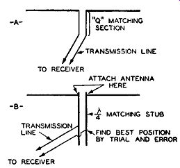
Fig. 4.23. Two methods of matching antennas to transmission lines.
However, if the signal level is appreciably below 100 microvolts it may readily happen that insufficient signal voltage will reach the set because of this mismatch. In this instance, use of a matching section between transmission line and antenna is highly desirable.
One method of achieving such a match is through the use of a special matching section called a "Q" section.
A section of transmission line, electrically one-quarter wave length long, is inserted between the transmission line and the antenna. (See Fig. 4.23A.) The line is then connected to one end of this quarter-wave section, and the antenna is connected to the opposite end. In order to match the antenna to the line, the characteristic impedance of the "Q" section must be the geometric mean between the characteristic impedances of the antenna and the transmission line. It can be found by the formula:
Zo = \/Za X Zt
…where Za = impedance of the antenna
Zt = impedance of the transmission line
Z0 = impedance of the matching section
To illustrate the use of this formula, let us apply it to the problem on hand, namely, that of matching a 72-ohm antenna to the 300-ohm line. In this case, Za = 72 ohms
Zt = 300 ohms
Zo = ? ( to be found)
Z0 = y21,600 = 147 ohms
147 ohms is an awkward value for a transmission line, but 150 ohms will do as well. Therefore, procure a 150-ohm parallel wire transmission line, cut it to a quarter wave length at the frequency used to design the antenna, and connect it between the line and the antenna, as shown in Fig. 4.23A.
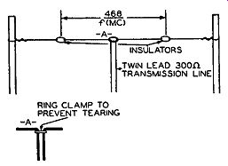
Fig. 4.24. A simple antenna constructed from a twin-lead transmission
line. This can be successfully used in areas of high signal intensity.
Another solution is to use a quarter wave matching stub. The stub consists of two rods or wires, their length being equal to a quarter wave length at the frequency used to design the antenna.
In any such quarter-wave section, the impedance varies from a low of 60 to 70 ohms at one end to several thousand ohms at the other end. Clip the antenna terminals to one end of each cord (or wire) of the quarter-wave section, and then experimentally shift the ends of the transmission line back and forth along each rod ( or wire) until maximum signal is reported at the receiver. Since the quarter-wave matching sections have a continuously varying impedance between 70 ohms to several thousand ohms, a point will be found where the impedance of the transmission line is matched. Fig. 4.23B illustrates the arrangement of the several components. Note that with this method any type of two wire line may be used for the matching stub. Its characteristic impedance can be of any value.
When the receiver is situated in a vicinity where the signal level is high (close to the transmitting station), the simple and economical lead-in antenna of Fig. 4.24 can be used. The twin-lead transmission line is slit down the center and suspended from two insulators to form a dipole antenna. A ring clamp is used to prevent the transmission line from tearing farther.
To summarize:
1. The input system should be matched at each point, i.e., the antenna to the transmission line and the line to the receiver.
2. For strong input signals, mismatching as much as 5 to 1 is permissible.
3. For nominal strength signals, a 2 to 1 mismatch is tolerable.
4. If a choice exists as to which point in the input system is to be mis matched, it is preferable that this occur at the antenna rather than at the receiver.
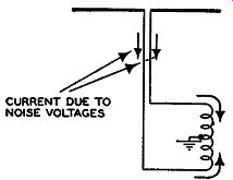
Fig. 4.25. With a parallel-wire transmission line, a balanced in put
coil is more effective in reducing the effect of noise voltages than
an unbalanced coil.
In noisy locations, where the transmission line must pass through areas where the noise generated by man-made machines is high, the use of a shielded lead-in is recommended. There is available shielded twin-lead trans mission lines ranging in characteristic impedance values from 95 to 300 ohms. When these are used, care should be taken to see that the metallic braid which is wound around the outside of the line, and which acts as the shield, is carefully grounded at several points along its path from the antenna to the receiver. It is also important that this shield be grounded at each end. Failure to observe these precautions will reduce the effectiveness of the shield and permit external voltages to reach the inner line.
Where the noise is only of mild intensity, its effects may be minimized if the 300-ohm unshielded line is twisted about every two feet on its way to the receiver. The purpose of this is to cause noise voltages to appear in equal strength in both conductors of the line. Since the currents developed by the noise voltages will flow in the same direction along both wires, cancellation at the receiver input will occur. (See Fig. 4.25.) Note that this will be true only when the receiver contains a balanced input, for then the two noise currents, made to flow through each half of the input in opposite directions, will effectively cancel each other. How well this cancellation is achieved will depend upon how well the input of the receiver is balanced.
There are some FM receivers which have an unbalanced input. For these sets the input impedance is generally 75 ohms, and a 72-ohrn coaxial line is recommended. At the antenna, direct connection of the inner lead of the coaxial line to one rod, and the outer shield to the other antenna rod, will provide satisfactory results if the signal level is high. Note, however, that only half the antenna is being utilized: that section which is connected to the inner coaxial cable. The other half of the antenna is grounded out by its connection to the outer conductor of the cable, which itself is grounded.
When this system is to be used in a weak signal area, better results can be obtained by a converter at the antenna which will provide a match be-tween the unbalanced 72-ohm coaxial cable, on the one hand, and the balanced impedance of the antenna, on the other. Such units are available at most of the large radio supply houses and consist of properly wound transformers.
FM TRANSMITTING ANTENNAS
The design and shape of FM transmitting antennas are governed (and, in the same sense, limited) by the following major considerations:
1. Horizontal polarization.
2. Location at center of service area.
3. Frequency allocations from 88 to 108 mhz.
The F.C.C. established horizontal polarization as standard for all FM broadcast signals, which requires, in general, that the radiating elements themselves be horizontally placed.
Antenna location at the center of the station service area is usually dictated by convenience, both with regard to studio placement and the relatively high expense of incorporating phasing networks to produce non-symmetrical radiational patterns. By placing the antenna at the center of its service area, a non-directional pattern is required.
Finally, there is the allocation of the FM broadcasting services to the frequency band extending from 88 mhz to 108 mhz. As noted previously in the discussion of wave propagation, signals with frequencies extending above 35 mhz are limited to the line-of-sight distance from the transmitting antenna to the horizon. This means that the extent of the area served by any one station depends upon the height of the antenna structure above the ground.
The higher the antenna, the greater the area over which its signals can be received. Now, one of the simplest methods of achieving height is obtained by erecting the antenna atop a high building. To do this effectively, how ever, requires that the antenna structure be light in weight and fairly compact. Furthermore, precautions must be taken to prevent the antenna structure from becoming an obstruction to aircraft, from accumulating too much ice, from becoming targets for static discharges and lightning, and from buckling under the strain of high wind velocities.
While the height of the antenna determines the line-of-sight distance to the horizon, full use of that area is not possible unless sufficient power is radiated by the antenna. High frequency operation imposes certain limitations on the amount of power that can be economically generated in the transmitter. To overcome this limitation to some extent, it has become general practice to design antennas which can concentrate whatever power they are given only in the desired plane, thereby reducing to a minimum the amount of power which is radiated in undesired directions. In the latter category would fall any power which is radiated vertically upward, since energy transmitted in this direction does not, at the present FM frequencies, return to earth. To achieve this concentration of energy in the horizontal plane requires the vertical mounting ( or stacking) of a number of units.
In the following pages, commercial FM antennas will be analyzed to determine how the foregoing specifications are attained. Fortunately, in the range from 88 to 108 mhz, such designs can be achieved with structures of moderate dimensions.
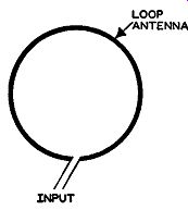
Fig. 4.26. A loop antenna.
The Cloverleaf Antenna. A very simple type of antenna which is capable of radiating a horizontally polarized wave to all points about the antenna in the horizontal plane is the loop antenna. (See Fig. 4.26.) The radiated field will be uniform if the current flowing around the loop is uniform, both in amplitude and phase.
To achieve this uniformity, the length of the loop (around its circumference) should not be greater than 1/8 lambda long. At the AM standard broadcast frequencies this restriction can be observed quite readily, even when the loop contains more than one turn. To remain within this restriction at the FM frequencies, however, requires that the loop diameter be extremely small, causing its input impedance to become quite low, and thereby making it difficult to feed power to the loop efficiently. Fortunately, the desirable radiation and polarization characteristics of the loop can be obtained without actually using a continuous loop. Instead, it is possible to employ a group of radiators which, when electrically combined, present the same electrical equivalent circuit as a loop. One such construction is the Cloverleaf antenna, shown in Fig. 4.27.
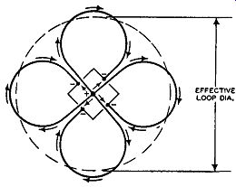
FIG. 4.27. Arrangement of four radiating elements constituting a radiating
unit of the Cloverleaf antenna. Arrows indicate assumed instantaneous
directions of current. (Courtesy I.R.E.)
The Cloverleaf antenna consists of four half-wave curved radiating elements. One end of each of the radiating elements is connected to a common central conductor of a coaxial line, while the other end of each of the four radiating elements is attached to a separate post of the tower structure which serves as the return conductor. With this arrangement, the currents coming up through the center conductor will, at point X, divide equally between the four radiating elements in the manner shown in Fig. 4.27. If we consider only outer portions of each curved radiator, we note that the current flows in the same direction in each one, producing effectively a circular flow of current. Points on each radiator which extend in toward the center of the Cloverleaf have currents flowing in them which are in opposition to the currents flowing in the adjacent radiator, with the result that the fields due to this portion of the antenna current flow cancel each other. Thus, only the currents flowing in phase at the outermost portions of each half-wave antenna are effective in developing the radiational pattern for this array.
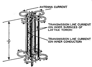
Fig. 4.28. A section of a Cloverleaf antenna showing two sections. Usually
a commercial structure contains four or five sections.
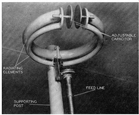
Fig. 4.29. A close-up view of a circular FM antenna. (Courtesy G.E.)
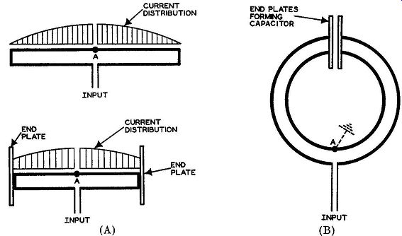
Fig. 4.30. Development of the circular FM antenna from a folded dipole.
To minimize the vertical radiation of the Cloverleaf, a series of four or five similar units are stacked one above the other, separated by distances of approximately one-half wave length. Two such units are shown in Fig. 4.28.
Since there is a voltage phase reversal at half-wave intervals along a trans mission line, the direction in which the individual radiating elements comprising each unit are curved is reversed. In this way the current flowing in all units all along the array do so in the same direction, and the field radiated by all sections is everywhere in phase.
Circular FM Antenna. Another approach to a loop antenna is the circular antenna shown in Fig. 4.29. This unit may, in a sense, be considered as a circular folded dipole. In a folded dipole, shown in Fig. 4.30A, the cur rent is maximum at the center, diminishing gradually to zero at the two ends of the dipole. (In contrast, the voltage is minimum at the center, increasing gradually toward the ends.) If, now, we place conducting plates at either end of the folded dipole, we accomplish two things. First, the overall length of the dipole decreases due to the capacitative effect of the end plates. Second, the current variation from the center of the folded dipole to either end is not as great as it is in the unloaded folded dipole. (See Fig. 4.30B.) Finally, by bending the dipole rods into circular form, a loop antenna is produced. The current distribution around the loop is now fairly uniform, producing a uniform field at all points around the antenna.

Fig. 4.30. Development of the circular FM antenna from a folded dipole.
By adjusting the separation between the two end plates, which form a capacitor, the resonant frequency of the antenna can be varied over the frequency range for which the unit is designed. This can be done without any change in the main physical structure of the antenna loop.
Since the voltage at the center of the folded dipole (point A of Fig. 4.30B) is very low, connection of a ground here will not noticeably affect the operation of the unit. Such connection is made in actual installations, with point A attached directly to the supporting pole. A transmission line then brings the transmitter power to the input terminals.
To minimize vertical radiation from the array, four to six circular antennas are stacked vertically.
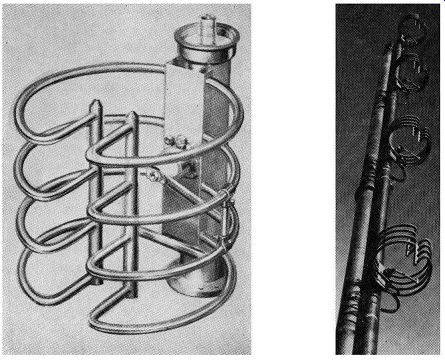
Fig. 4.31. Broadband dipole FM broadcast antenna. Left: A single bay.
Right: Four bays, vertically stacked. (Courtesy RCA)
RCA Broadband Antenna. The RCA broadband antenna, shown in Fig. 4.31, consists of four dipoles bent into the shape of a ring. Instead of connecting plates to the ends of the dipoles to form a resonating capacitor, the RCA unit achieves the same purpose by curving in the ends of the dipoles.
Of the four dipoles used for each section, only the center two are powered.
The remaining two end elements are parasitic; their purpose is to broaden the response of the driven elements so that uniform transmission can be achieved over any channel in the 88-108 mhz band. This is useful in multiplex broadcasting where two signals are transmitted simultaneously. Each shares the band normally utilized by one signal.
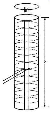
Fig. 4.32. The Pylon antenna may be considered as being made up of a
large number of circular elements, each of which radiates.
To insure uniform transmission of both signals, a wide-band antenna is needed, one that can provide close matching to the transmission line over the full 150- khz channel. When only a single signal is being transmitted, the matching requirements are less severe.
A 50-ohm coaxial transmission line feeds each broadband section. Both driven elements are fed in parallel, with the feedpoint located as shown in Fig. 4.31 (left) to obtain the proper impedance match. Furthermore, since the feed line is mechanically rigid, it also serves to act as a strengthening support for the dipole elements.
The Pylon Antenna. The operation of the Pylon, or slotted tubular antenna, also is based on the loop. In appearance this antenna is a cylinder, each section of which is approximately 13 feet high and 19 inches in diameter with a narrow slot cut from top to bottom. The cylinder is fed by a single transmission line running up the inside of the cylinder to the midpoint of the slot.
To understand the operation of the Pylon, consider it to be composed of a large number of circular elements, each of which functions as a loop antenna.
(See Fig. 4.32.) When power is fed to the slot, it functions as an open wire transmission line, establishing a voltage distribution along the length of the slot as shown in Fig. 4.33, and causing currents to flow around the surface of the cylinder. Since these circumferential currents are very nearly in phase throughout the length of the cylinder, a field is radiated which is very nearly the same at all points in the horizontal plane. (See Fig. 4.34.) Pylons may be stacked in one, two, four, or eight sections, the gain in creasing with the number of sections. Furthermore, as the number of sections increase, the power radiated in the vertical direction decreases. It is important that each Pylon section is fed in phase, and this is accomplished by using suitable lengths of transmission lines.
Mechanically the Pylon cylinder is rolled from a single sheet of metal.
It is capped on each end with a cast base to give the unit greater mechanical stability.
The Square-Loop Antenna. The circular radiation pattern of the loop can be obtained even when the shape of the loop is not circular or the cross section of the radiator is not round. In fact, the loop elements can be square, rectangular, or even triangular, without modifying the essential electrical behavior of the loop. Advantage is taken of this in the square loop FM antenna. (See Fig. 4.35.) To understand the electrical and physical construction of the square loop antenna, consider the two half-wave radiators, A-B, and C-D, in Fig. 4.36A. Each radiator is fed from a common point, E, and since the distance, E-A, is equal to the distance, E-C, the instantaneous voltage polarity at points A and C will always be the same. Hence, the currents flowing in A-B and C-D will, at any instant, be flowing in the same direction as indicated by the arrows, producing the equivalent of an in-phase cur rent all around the circular path.
If the feeder line AEC is exposed, it, too, will radiate, tending to destroy the desired circular radiation pattern of the loop sections, A-B and C-D. To prevent this, the arrangement shown in Fig. 4.36B is employed. A coaxial transmission line is used for the feeder, and sections A-B and C-D are made rectangular in shape, with their center hollow. To feed section A-B, the inner conductor from point E goes to point G, where it enters at the center of section C-D and travels through the interior of this section until it reaches point A. At this point it makes electrical contact with section A-B.
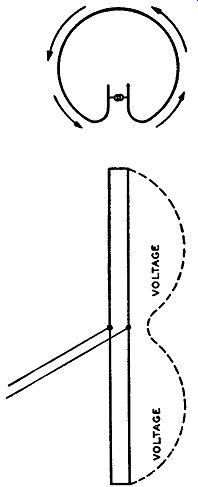
Fig. 4.33. Power is fed to the slot which functions as a transmission
line. Currents flow around the circular path as shown.
To feed section C-D, another inner conductor extends from point E to point H, enters at the mid-point of section A-B, travels through the interior of A-B until point C is reached where electrical connection is made to section C-D. Thus, both feed lines from E are shielded until they actually reach the rectangular radiating sections, A-B and C-D. The current distribution from end to end of each section (A-B or C-D) is maximum in the center, diminishing to a minimum at either end. By making the length of each section somewhat less than a half wave length and utilizing the end effect of each section, the difference between maximum and minimum current is only 12 percent. This results in a radiation pattern which is very nearly circular.
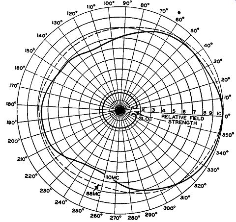
FIG. 4.34. The horizontal field pattern of the Pylon for frequencies
at either end of the FM band.
While the current at the center of each section is a maximum, the voltage here is very low, and actually grounding this point to the supporting structure does not noticeably affect the operation of the antenna. The outer conductor of the feeder coaxial cable also connects to the radiating section at this mid-point, while the inner conductor extends into the center of the radiating section.
In one commercial application of this FM antenna, the number of sections is not two but four, permitting the circumference to be increased to approximately two wave lengths. The electrical transition from the two sections discussed above to four sections is shown in Fig. 4.37. As seen, the instantaneous current along the radiating members are always in the clock wise or counterclockwise direction.
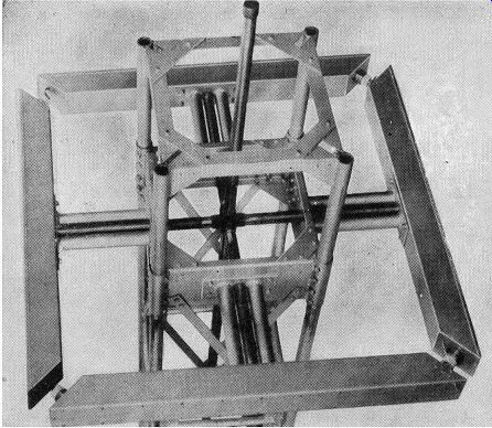
FIG. 4.35. A square-loop FM antenna.
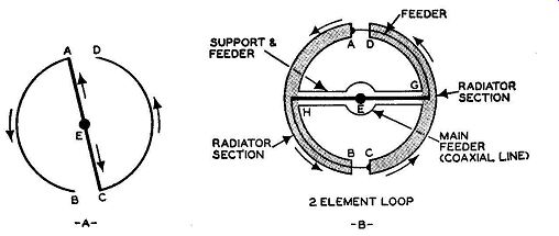
FIG. 4.36. Two steps in the development of the square-loop antenna.
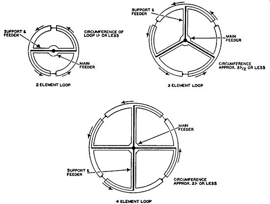
Fig. 4.37. Evolution from a two element to a four element loop. For
ease m understanding, the loops are shown as circular, although in the
FM antenna of Fig. 4.35, the loop is rectangular.
The Turnstile Antenna. An FM antenna which has been widely used is the turnstile antenna shown in Fig. 4.38. Essentially this antenna consists of two half-wave dipole antennas, positioned at right angles to each other, and fed 90° out of phase. The radiation pattern from each dipole is the familiar figure-8 pattern. However, by positioning the two half-wave dipoles at right angles to each other and then feeding them as indicated, we obtain an overall pattern which is closely circular. Furthermore, the energy radiated by this system is horizontally polarized, which makes it suitable for FM broadcasting. Finally, to minimize radiation in the vertical plane, a series of 3 to 5 turnstile units are mounted above each other, spaced by distances of approximately one-half length.
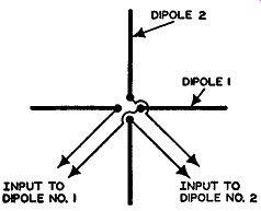
Fig. 4.38
The turnstile, as originally designed, contained simple dipoles as the radiating elements. However, folded dipoles may be used as well and, in fact, have so been used. (See Fig. 4.39.) The folded dipole possesses a higher point input impedance than the simple dipole and for this reason is more desirable from the standpoint of impedance matching and power transfer from the transmitter to the antenna system. Furthermore, the transmission line feeding system for the folded-dipole turnstile array can be designed so that the center of the folded dipole may be grounded to the supporting mast, affording protection against lightning and static discharges. The radiation pattern of a folded dipole is the same as that of a plain dipole.
The super-turnstile antenna represents a further improvement in turnstile antenna design.
In place of the simple dipole arms, solid radiating sheets approximately one-half wave length high are used. (See Fig. 4.40A.) In actual construction, the solid sheets are replaced by an open framework as shown in Fig. 4.40A and 4.40C because it was found that essentially the same results could be obtained.
The operation of the super-turnstile antenna and the reason for its peculiar shape may be understood by considering that a pair of super turnstile radiators form a large plane surface containing a slot. In Fig. 4.41 such a slot is shown, the length of the slot being one-half wave length long, with the ends of the slot grounded.
If, now, we connect a generator across the center of the slot, the voltage potential which will be established along the slot is indicated by the distance of the dotted lines from the sides of the slot. It is evident that the voltage potential will be greatest at the center of the rectangular slot, gradually diminishing to zero at the ends of the slot. Currents will flow in the plane surface with a magnitude and instantaneous direction as shown by the arrows. This same distribution of voltage and current will be obtained whether a solid metallic sheet is used for the plane surface or an open framework.
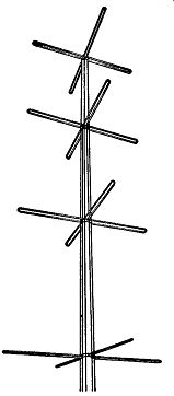
Fig. 4.39. A turnstile antenna array using folded dipoles.
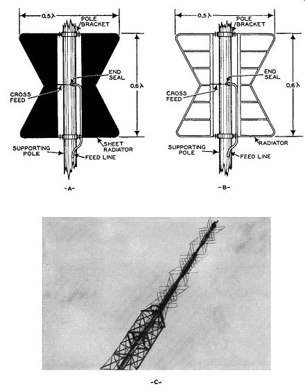
Fig. 4.40. (A) The original form of the super-turnstile antenna using
solid sheet radiations. (B) The present commercial appearance of the
super-turnstile using an open framework. (C) An actual photograph of
a super-turnstile antenna. (Courtesy RCA)
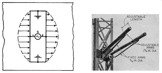
Fig. 4.41. Currents and voltages in the region of the half-wave slot
in a large conducting surface.
Fig.4.42. The Multi-V, FM broad cast antenna. (Courtesy Andrew Corporation)
The radiators are attached to the supporting pole at the top and bottom.
The R.F. currents in the side rods will radiate proportionately to the length of each rod and to the current in that rod. Hence, to obtain uniform radiation from each rod, the length is made inversely proportional to the amount of current flowing in the rod. Thus, at the center, where the current distribution is high, the rod length is made small; to obtain the same amount of radiation near the ends of the slot, where the current is small, the length of the radiators is increased. In this way, a very close approximation to the radiation pattern of two simple dipoles, spaced one-half wave length apart, is obtained.
To obtain a circular radiation pattern, each super-turnstile bay contains a pair of radiators facing north and south and a pair facing east and west.
Energy concentration in the horizontal plane is achieved, as in previous arrays, by mounting several bays above each other. Feeding of each pair of radiators is done at the center of the unit.
Multi-V Antenna. The Multi-V antenna is a lightweight transmitting array formed into the shape of a V. (See Figure 4.42.) This configuration gives a horizontal radiation pattern which is very nearly circular.
In order to achieve the desired input impedance, a folded dipole V is utilized. This gives rise to two sets of arms for each leg of the V. One of these arms is fixed and has a diameter of 5/8 inches. The other arm of each set is adjustable, with a telescoping end section for frequency variation. Diameter of this arm is 1 ¾ inches. By this arrangement, a simple adjustment tunes the antenna to resonance anywhere in the FM band without appreciably affecting the input impedance.
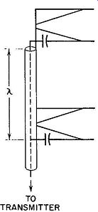
Fig. 4.43. Method of feeding the Multi-V antenna.
Another advantage of this tuning arrangement is that the two ends of the V are far enough apart to permit 5 kw or more of power to be fed into the array.
Since this is basically a half-wave antenna, maximum R.F. voltage appears at the ends. In the V antenna, these points are separated sufficiently to prevent arc-over.
As commonly employed, several V sections are positioned one above the other. R.F. energy from the transmitter is then brought to each bay by means of a 51.5-ohm coaxial cable, as shown in Fig. 4.43. Three of the four elements of one V array connect to the outer coaxial conductor; the other conductor is capacitative connected to the coaxial inner conductor. In or der to feed the two bays in phase, they are separated by one wave length along the coaxial cable. The actual distance is somewhat less than one full free-space wave length because of the reduced velocity of electromagnetic waves along the cable.
EXAM
1. Name the various categories into which radio waves can be divided.
2. What is the ionosphere and of what use is it?
3. Describe the convention regarding the polarization of radio waves.
4. Name the three general layers in the ionosphere. At what average heights can they be found?
5. Why is the ionosphere useful for long-distance communication? Which layer is responsible for the bending of 35-mhz waves? Why?
6. What is the difference between reflection and refraction?
7. Name three conditions upon which ionospheric refraction depends.
8. What is meant by the critical frequency of an ionospheric layer?
9. What is the Sporadic E layer? What is its significance?
10. Does U.H.F. propagation differ from low-frequency radio wave travel? Explain.
11. Name the three methods whereby U.H.F. waves are propagated.
12. What is the range of frequencies that can be normally refracted by the ionosphere?
13. Discuss the line-of-sight method of propagating U.H.F. waves, deriving the equations applicable to this method.
14. What primary factors determine the amount of voltage developed in a receiving antenna?
15. What is the wave length of a 100-mhz wave?
16. What would be the length of a half-wave dipole tuned to 106 mhz?
17. A half-wave dipole antenna designed for 108 mhz is to be used at 88 mhz. By how much should its length be altered?
18. Name and sketch five different types of antennas that could be employed to receive FM signals.
19. What precautions must be observed in choosing and installing a transmission line?
20. Define antenna gain and antenna directivity.
21. Illustrate a balanced and unbalanced input system.
22. Name and describe four types of transmission lines.
23. Discuss briefly the effects of impedance mismatch in the antenna system.
24. Describe two methods of matching impedances between the antenna and the transmission line.
25. What general factors determine the design and shape of FM transmitting antennas? Discuss each item briefly.
26. Sketch the Multi-V antenna and describe its operation.
27. How is the amount of energy radiated vertically by an antenna minimized?
28. Explain the operation of the antenna in Fig. 4.29.
29. Compare the operation of the Pylon and square-loop antennas.
30. Explain the operation of the turnstile and super-turnstile antennas.
+++++++++++