Design Factors of I.F. Amplifiers. The superiority of the superheterodyne lies in its I.F. amplifiers. The incoming signal frequency is purposely lowered to a level where a large degree of amplification is more readily, and efficiently, achieved, using conventional radio components. In addition, it permits the designing of fixed tuned circuits with a bandspread sufficiently wide to include all the sideband frequencies arising from modulation. An engineer, designing a tuned circuit for use at one frequency only, can better obtain the maximum amplification than when he is faced with the prospect of having to adapt the circuit for uniform operation over a range of frequencies. A coil designed to function over many frequencies, such as is necessary in the input stages of a receiver, generally produces uneven amplification over the entire band. In Fig. 7.1 is shown a curve illustrating the variation in the Q of a coil (wL/R) with frequency over the standard broad cast band. Note that the Q has a high value at the beginning and then drops fairly rapidly at the higher frequencies. This latter decrease is due to the fact that R increases more rapidly than wL with the rise in frequency. R represents a combination of:
1. Losses in the form on which the coil is wound.
2. Skin effect, which confines the current to a narrow layer near the surface of the wire.
3. Eddy current losses in near-by metallic objects.
Through the use of a circuit tuned to one fixed frequency, the amplification and selectivity may be held constant-adding to the stability of the receiver.
In the design of an I.F. amplifier, or an I.F. system containing several stages, three basic factors must be considered:
1. Frequency of the I.F. stages.
2. Gain.
3. Selectivity.
These quantities are certainly interrelated, but the general procedure is to choose first the operating frequency and then to consider the problems of gain and selectivity together.
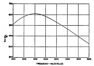
Fig. 7.1. The variation of Q (of a coil) with frequency.
Choosing the Intermediate Frequency. The choice of an intermediate frequency may appear, at first, to be quite simple since we know that at the lower frequencies it is easier to arrange and design circuit components to obtain high gain. However, there is a limit to the low frequencies that can be used because of the stability of the oscillator and other circuit components located ahead of the I.F. stages in the receiver. When a set is first put into operation, it may require as much as an hour or so before the oscillator frequency becomes stable. When ordinary parts are used in the construction of a receiver, the oscillator may drift as much as 0.2 percent in frequency. At 95 mhz, this means a drift of 190 khz. With a low value of I.F., the station would soon drift outside of the I.F. range. Through compensation of an oscillator, such as the use of low-loss tube sockets, careful wiring, capacitors with negative temperature coefficients, etc., the amount of drift can be lowered to a figure of 0.05 percent of the carrier frequency or 48 khz.
This is a considerable improvement over the previous uncompensated figure.
Further improvement can be achieved only at much greater cost, perhaps involving specially constructed components or the use of crystal-controlled oscillators.
A second limitation on the use of a low I.F. is the tendency of most oscillators (excepting, possibly, crystal oscillators) to lock-in with other more stable oscillators when they are quite close in frequency. With a low I.F., a strong signal could readily pull the oscillator out of its desired position into the same frequency as the signal. As might be expected, under these conditions, no difference or intermediate frequency will be produced.
Still another consideration governing the choice of an I.F. value is the spread of the incoming signal. An FM broadcast, fully modulated, occupies a frequency bandwidth of 200 khz. Obviously, it would be ridiculous to use any I.F. below this figure, for then how would it be possible to vary an I.F. of say 125 khz plus and minus 200 khz? There are no negative frequencies.
Hence, an LF higher than 200 khz is necessary. But how much higher? 400 khz? 800 khz? 1 mhz? or still higher? Before we definitely answer this question, let us investigate the different types of spurious responses capable of affecting a receiver and their influence on the choice of an intermediate frequency.
Spurious Responses. A spurious response is defined as the reception of a signal at a point other than desired on the dial. For example, a station may be received at more than one point on the dial, or two or more stations obtained at the same time when only one should be present. In using the phrase "spurious response," we refer only to interference caused by stations appearing at undesired points of the dial. Atmospheric and man-made noises are not included.
The most important spurious responses to which an FM set is subjected arc:
1. Image response.
2. Response of two stations separated in frequency by the I.F. value.
3. Direct I.F. response.
4. Combination of harmonics from oscillator and signal.
We may pause here and note that the appearance of any of these spurious responses is in no way connected with the noise-reducing qualities of frequency modulation discussed in Section 1. Any interfering signal, either arising from one of the sources listed above or from another station on the same channel, will be completely suppressed if the desired signal is at least twice as strong as the interference. However, the danger lies in the fact that this relationship may not exist. In fact, the undesired signal may be many more times stronger than our desired signal. In such an event, the desired signal could be either badly distorted or else completely obliterated. The choice of an I.F., coupled with proper design, will do much to minimize the interference from the four main sources of spurious responses.
Image Response. Image response is due to the mixing of an undesired signal with the oscillator voltage in the converter stage to produce a voltage at the intermediate frequency. Since a frequency equal to the intermediate frequency is produced, this signal will be accepted and passed by the I.F. amplifiers. To understand how this may occur, suppose that a receiver is tuned to a station at 95.3 mhz. With the oscillator set at 99.3 mhz, the difference (4.0 mhz) which is also the intermediate frequency will be produced in the frequency converter or mixer plate circuit and fed into the I.F. stages.
Modulation would swing the carrier ±75 khz about the center value.
Now suppose-and this may readily happen-that there is another powerful station in the vicinity operating on a frequency of 103.3 mhz. If sufficient selectivity is not provided ahead of the converter stage-or an R.F. stage of amplification is not included in the set-then an appreciable amount of the signal voltage from the 103.3 -mhz station may appear at the converter grid. Subsequent mixing with the 99.3 -mhz voltage from the oscillator will produce a difference frequency of 4.0 mhz which is also equal to the I.F. This second interfering signal is referred to as an image station.
It makes little difference-so far as the production of image response is concerned-whether the oscillator frequency is higher or lower than the de sired station. In the preceding example, the oscillator was operating above the desired signal. It may also be located lower in frequency by an amount equal to the I.F. In fact, most manufacturers prefer the lower oscillator frequency because of the increased stability of oscillators at lower frequencies.
Using the last example, but with the oscillator below the desired signal, say at 91.3 mhz, an image response will be obtained if the signal is below the oscillator by an amount equal to 4.0 mhz. In this instance, this would mean a station at 87.3 mhz. Under present allocations, the FM band starts at 88 mhz and no FM station is located at 87.3 mhz. However, if we tuned the receiver to another station, say at 97.3 mhz, then with the oscillator at 93.3 mhz and the image station at 89.3 mhz we create a possibility for an image response.
It will be noted that, whenever the oscillator frequency is higher than that of the desired station, the image is above the oscillator by an amount equal to the I.F. On the other hand, the image station is lower in frequency than the desired station when the oscillator is also lower. The image station and the desired signal are always separated from each other by an amount equal to twice the I.F. value. This is shown in Fig. 7.2.
One solution for minimizing interference due to images is increasing the selectivity of the tuned circuits preceding the converter stage. Not only is the number of tuned circuits important but also the attenuation they impose on any signal extending beyond the ±100- khz limits of the desired station.
It is generally operationally difficult and most times economically impractical to develop in these high frequency input circuits a high degree of selectivity. At the low frequencies, one megacycle separation between signals represents a considerable percentage of the carrier frequency. Thus, for ex ample, two stations separated by one megacycle at 15 mhz could be resolved readily, without interference, by a circuit possessing a much lower Q (and, hence, selectivity) than if the carrier frequency is raised to 90 mhz. It is not the numerical frequency difference between stations that is important but the percentage difference. In the first case, the percentage separation is approximately 6. 7 percent; at 90 mhz, a 1-mhz separation represents a percentage separation of approximately 1.1 percent. Two tuned circuits possessing the same selectivity could be more economically manufactured at the low frequencies than at the high frequencies.
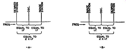
Fig. 7.2. The relationship between the desired and image stations when
the oscillator frequency is above (A) and below (B) the signal frequency.
The foregoing illustration is one reason why superheterodynes have proved so popular. In a superheterodyne, the signal on reaching the receiver is converted or "stepped-down" to a lower frequency which is known as the intermediate frequency. Once the frequency is lowered, we can better apply selectivity and gain to the signal than if it had remained at 90 or 100 mhz, its incoming value. No lowering occurs in tuned radio-frequency receivers which are practically out of production except in very cheap sets built to receive the standard broadcasting frequencies. Despite additions of R.F. amplifier stages to a receiver and despite any sharp selectivity of the input resonant circuits, it is still the I.F. amplifiers which are chiefly responsible for the selectivity or sensitivity obtainable from a superheterodyne.
The choice of an I.F. has a direct bearing on the amount of image response to which a set is subjected. If the I.F. is too low, say 1, 2, or 3 mhz in value, then the possibility of interference from image stations is correspondingly increased because of the small percentage difference between the de sired signal and an image signal. Raising the I.F. provides a greater separation between these signals and makes it easier for the preliminary or input circuits to weaken the interfering signal-weaken it probably to the point where the desired signal could normally override it. In practice, it is common to make the I.F. slightly greater than half the width of the entire FM band. Thus, since the band extends for 20 mhz--from 88 mhz to 108 mhz--an I.F. of 10.7 mhz would eliminate interference from image stations entirely.
The reason is quite simple. We have just noted that the desired station and the image station are always separated by 2 x I.F. value (see Fig. 7.2). But, if 2 x I.F. value is greater than the width of the entire broadcast band, then it is obvious that the reception of image signals, within that particular band, is impossible.
Of course, we must not overlook the possibility of stations on adjacent bands causing trouble. Thus, for instance, adjacent to the FM band, 88 108 mhz, at the lower side is the television band, 82-88 mhz. However, sufficient discrimination is provided by the input resonant circuits to make this possibility small.
Stations Separated by the Intermediate Frequency. The second source of spurious response listed is interference arising when two signals mix, both separated in frequency by an amount equal to the I.F. of the receiver. In this situation, one incoming signal acts as the mixing oscillator for the other signal, their difference frequency appearing at the output of the mixer or converter stage as the intermediate frequency. As an illustration of this type of spurious response, consider a receiver where the input selectivity is such that two signals, say 90.3 mhz and 99.4 mhz, are present at the converter grid in appreciable strength. When these mix with each other, in the converter circuit itself, a difference frequency of 9.1 mhz (the I.F., say) will appear. The oscillator of the set itself does not enter into this action, and with poor input selectivity these two stations will be present no matter where the set is actually tuned. Hence, they will be heard all over the dial.
There are two solutions to the problem. One is to provide sufficient discrimination in the circuits preceding the mixer that they will reject two signals so widely separated in frequency. The other is to provide a high I.F., preferably an I.F. slightly greater than the entire bandwidth. In present-day operation, this would mean an I.F. above 20 mhz. By so doing, we make it impossible for any two stations within the band to mix with each other at the converter (providing they reach this stage) to produce a difference frequency equal to the receiver I.F. Direct I.F. Response. The third type of spurious response that may arise is due to direct reception of a frequency equal to the receiver I.F. itself.
If some station or service is transmitting at the I.F. value used in the receiver, this signal could easily reach the I.F. amplifiers either through the usual input channel or else directly by the development of the signal voltage on the grid of the first I.F. amplifier when adequately shielding is not provided. That this can be a serious source of trouble has been demonstrated by many tests.
To forego the need of incorporating special filters, wave traps and shielding to prevent interference from the latter source, an I.F. is chosen whose frequency is seldom that of any commercial transmission. This accounts for such seemingly odd figures as 4.3 or 10.7 mhz for the value of an I.F. On many frequencies, the only traffic is ship-to-shore messages or perhaps traffic between mobile experimental equipment, etc. These frequencies have been set aside by the government for the particular services. Since the stations operating at these frequencies are not very powerful, the possibility of their interfering with our home receivers is fairly remote. Hence, these frequencies are chosen for the I.F. in the receiver.
Harmonic Spurious Responses. The fourth and final item on the list of spurious responses is the production of interference from harmonic relationships occurring between signal and oscillator voltages that could pro duce a voltage at the I.F. value. Perhaps the best way of demonstrating this source of spurious response is by an actual example. Suppose the oscillator is at 95.1 mhz. Its second harmonic would be at 190.2 mhz. If a strong signal of 89.7 mhz overloads the input of the receiver, a very good chance exists that its second harmonic would be formed, the frequency being 2 X 89.7 mhz, or 179.4 mhz. The difference between 190.2 mhz and 179.4 mhz is 10.8 mhz. This would reach the plate circuit of the converter stage and be accepted by an I.F. amplifier designed for 10.7 mhz.
The probability of the foregoing situation occurring in a receiver depends to a great extent upon the care taken in the receiver design. Since the appearance of this form of spurious response depends upon the generation of secondary harmonics of both a signal and the oscillator, the obvious solution is to minimize the possibility of such harmonics. In the oscillator, it is almost impossible to prevent the appearance of harmonics because of the nonlinear operation of the circuit itself. In general, though, the strength of the harmonics decreases with the order of the harmonic. Thus, the fundamental frequency component is strongest, the second harmonic not quite as strong, the third harmonic weaker still, etc. The rapidity with which the strength of the harmonics decreases is a function of the Q of the tank circuit. The higher the Q, the greater the harmonic attenuation.
At the converter, best results are achieved at some value of oscillator voltage. This means that if the oscillator injection voltage is kept at or slightly below the optimum figure, the largest amount of I.F. voltage will be obtained at the converter output. Increasing the oscillator voltage does not improve the amount of desired I.F. produced, but it does strengthen the effectiveness of the harmonics of the oscillator in the conversion process.
Hence, one way to minimize the effect of the oscillator harmonics at the converter is not to overload the converter with oscillator voltage.
To minimize the formation of any second harmonic components of signals appearing across the receiver input, the circuits should possess adequate selectivity. All R.F. tubes should be of the variable mu type, preferably con trolled by some small amount of A VC. Although a sharp cut-off tube generally has a greater gm (mutual conductance) and hence capable of greater gain, it is, at the same time, more easily overloaded, a condition that readily leads to the production of harmonics. By forfeiting a little gain and using a variable mu tube with a small amount of controlling A VC, we can also re duce the production of harmonics. The A VC voltage is obtained from the limiter, or, if necessary, from the discriminator.
Fig. 7.3. An ideal selectivity response curve. All frequencies having values above 10.7 mhz + 100 khz and below 10.7 mhz - 100 khz are rejected by the circuit.
The foregoing discussion has, by no means, exhausted the subject of spurious responses. However, the important sources have been covered and sufficient information obtained to understand their effect on receiver design and operation. It is quite evident that a high I.F. is desirable, and to a certain point, the higher the better. Against the use of a high I.F. are the disadvantages of reduced gain, necessity for greater care in choosing components to prevent excess losses, additional shielding and increased tendency toward feedback through the tubes and adjacent circuits. Also, we have the ever-present requirement of selectivity which rears its head at every turn and is certainly one of the most important factors in any consideration of operating frequency. All these factors must be weighed against each other and the trend of late is to use high intermediate frequencies. For the F-:YI band, the choice is 10.7 mhz.
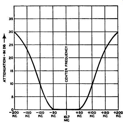
FIG. 7.4. The practical selectivity curve of an FM receiver.
Gain and Selectivity. After the frequency of the I.F. system is chosen, we are faced next with the problems of gain and selectivity. So far as the latter is concerned, the response should be uniform up to the sideband limits on either side of the carrier. A desired shape for the response curve is shown in Fig. 7.3. In general, though, the expense involved in attempting to con struct a circuit possessing anywhere near such a response characteristic is prohibitive. The more readily achieved curve, shown in Fig. 7.4, is one practical compromise. At the plus and minus 75- khz points from the carrier, the response is down about 4 db. In terms of voltage attenuation, this rep resents a decrease in the ratio of 1.25 to 1. At 100 khz the attenuation has risen to 10 db (3.2 to 1), and at 200 khz from the carrier, it has reached 30 db (14 to 1). These represent figures which can be achieved in practice and which tend to provide the necessary discrimination against unwanted signals in adjacent channels. It must be understood that when we assign a figure such as a 30-db loss at 200 khz, we are referring to the total attenuation of the I.F. system and not to any single stage. Thus, suppose there are four tuned circuits in the I.F. system. Then each circuit contributes ¼ of 30db, or 7.5 db. The overall curve, though, would introduce this much loss to the particular frequency attempting to pass through the amplifiers.
When we speak of the selectivity of a tuned circuit, we refer actually to its Q. Q is defined as the ratio of the inductive reactance of the coil in the tuned circuit to the a-c resistance of that coil. When the Q is high, the impedance presented to any frequency (or narrow band of frequencies) is high, resulting in a large voltage being developed across the coil (at that frequency). When circuits are inductively coupled this results in a large transfer of energy between them. At other frequencies, the opposition offered is not as high, and the transfer of energy is reduced. Here is where the loss, or attenuation, arises at these other frequencies.
The overall selectivity curve (Fig. 7.4) is the product of the Q of each tuned circuit in the system. Each set of coils must be properly wound, correctly spaced and, at the high frequencies, loaded down to produce the proper characteristics. Not only must the engineer determine the effect of Q on attenuation but also its effect on the gain of a stage, because the stage amplification is governed by the formula wLQ A= gm- 2
… where …
gm = mutual conductance of the tube and wL = inductive reactance of the coil. This formula is based on a double tuned arrangement (Fig. 7.5)
… where L1= L2 and Q1 = Q2.
This is customary as it simplifies mass production.
The special importance of gain in its relation ship to limiter operation is discussed at a later point. In the tuned circuit, a high Q means a high L to C ratio. The higher L is, the more inductive reactance (wL) is presented to the tube and the greater the output voltage.
But from the formula 1 f=- 21rvUf
... where L = inductance in circuit
C = capacitance across coil
f = resonant frequency at which circuit functions we see that, for any one frequency, large L requires a correspondingly small C. The extent to which C can be lowered depends upon:
1. The capacitance presented by the tube.
2. The stray wiring capacitance.

Fig. 7.5. A double tuned transformer. For ease in production, L1 = L2
and Q1= Q2.
For a typical case, 6BA6, with a mutual conductance of 4400 micromhos, has an output capacitance of 5 mmf. Stray wiring capacitance may amount to an additional 5 to 10 mmf, depending upon how well the layout was accomplished. Thus, from these extraneous sources alone we have 15 mmf, and this will represent the minimum capacitance. If a coil is designed which utilizes only the stray capacitance, the operation of the amplifiers may be-come unstable because of the changes that occur in this capacitance with heat, length of operation, moisture and other factors. The I.F. tuned circuits would repeatedly shift frequency each time the set was operated. Good reception would be difficult. Experience has demonstrated that a physically inserted capacitor of at least 35 mmf should be included for stable operation.
However, this limits the highest value of inductance for any one frequency and consequently places a ceiling on the gain possible for any stage.
The gain of a stage also varies directly with the mutual conductance of the tube, and a high g_m value is desirable. The particular usefulness of a high g_m is the large change in current flow caused by a relatively small change in grid voltage. In any plate load circuit, whether it be resistive or inductive, a large current variation gives rise to a large voltage drop and a consequent increased transfer of energy. After all, amplification within any circuit is merely a measure of the effect a small incoming voltage has in producing a large output. The greater this ratio, the higher the amplification factor. A high g_m is one way of achieving this goal.
To obtain greater values of mutual conductance, it is necessary that the grid exercise greater control over the electron current flow within the tube.
Increased cathode emission, by an increase in the cathode area, would result in a greater transconductance. The interelectrode capacitance, however, would also increase by as great a factor, further limiting the L/C ratio of the tank circuit. One solution employed in the design of many miniature tubes is based upon the fact that by bringing the grid closer to the cathode, gm would increase inversely as the square of the spacing, whereas Cuk would only rise inversely as the spacing. In other words, the g_m would rise more rapidly than the interelectrode capacitance. To a certain point this procedure is advisable but its limits-both in the nearness to which the grid can approach the cathode and the amount of interelectrode capacitance that can be tolerated-are quite evident.
Due to the importance of the interelectrode capacitances and the mutual conductance of a tube in determining the gain and stability of an amplifier, a "Figure of Merit" has been assigned to tubes on the basis of their ratio.
Expressed mathematically, Figure of merit = C1n + Cout !mCup(A + 1)
where ... C1n = the input capacitance of the tube
Gout = the output capacitance of the tube
Cup = capacitance between grid and plate electrodes
gm = mutual conductance of tube
A = amplification of the stage
The values for the three capacitances can be obtained from any tube manual. The same is true for Gm. The value of the stage amplification, how ever, must be computed. The amplification is given by the equation A= ZL X gm where ZL is the load impedance expressed in ohms and Gm in mhos. For the tuned circuits used in the I.F. stages of an FM receiver, we can assume a nominal value of 10,000 ohms for ZL. With the value of A computed, we may substitute in the formula given above to determine the value of the "Figure of Merit." Table IV contains a list of current pentodes with their relative standing.
TABLE IV
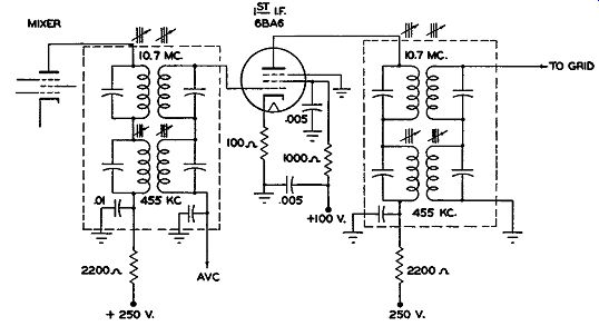
FIG. 7.6. An I.F. amplifier. The symbol above each coil indicates permeability
tuning. (Courtesy RCA)
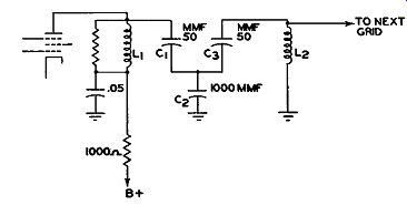
FIG. 7.7. A complex interstage coupling network.
The procedure for choosing a tube for use in an amplifier is to tabulate a list of all suitable tubes and then pick the one that has the highest "Figure of Merit." We have undertaken a fairly detailed inspection of the operation and design of high-frequency I.F. amplifiers because of the importance of these details to those who are going to service or build such amplifiers. Every single component, down to the exact layout of the wiring, must be taken into careful consideration in either repairing or building an FM receiver.
But, without an understanding of the reasons behind this necessity, repairing or construction of sets soon devolves into a mechanical procedure, easily forgotten-certainly never appreciated. It is only when one has a full appreciation of the task can the best results be obtained.
Commercial I.F. Amplifiers. Schematically, the I.F. amplifier of an FM receiver (excluding the limiters for the present) does not differ in form from those amplifiers with which we are familiar from sound broadcast receivers. A typical diagram is shown in Fig. 7.6. The general tendency in these higher frequency interstage coupling units is to vary the frequency of the tuned circuit by means of permeability tuning. The threaded core is some magnetic material, generally powdered iron. It is threaded and, as it is moved deeper into the center of the coil, it acts to increase the inductance of the coil thereby decreasing the resonant frequency. The advantage of this method of tuning over a variable capacitor is that it permits a higher inductance to be used and a wider tuning range to be covered. The capacitance associated with the inductance at a high I.F. is kept, as we have al ready noted, as small as practical. With a small variable capacitor only a limited tuning range is possible.
To cover a greater range, a large capacitance would he required. But to accommodate the larger capacitance, L would have to he lowered. ·with a decrease in the L/C ratio occasioned by such a procedure, a decrease in gain would occur-hence the advisability of permeability tuning. From time to time manufacturers employ complex coupling between stages in place of the usual two-coil arrangement shown in Fig. 7.6. Fig. 7.7 is indicative of this type of a circuit. Here L1 and L2 are not inductively coupled to each other.
Rather the transfer of energy takes place through the three capacitors C1, C2, and C3. C2 is the common coupling capacitor, being common to both circuits. Since the transfer of energy takes place in this manner, the circuits are said to be capacitatively coupled. The advantages to be gained through such an arrangement are greater selectivity and a more uniform response throughout the desired range. Its disadvantage is increased cost.
There are many similar combinations possible and probably the reader has encountered some of them at one time or another. Their only difference from the double-tuned transformer is in the response they offer and the attenuation imposed on adjacent channel signals. They are widely used in television, where signal bandwidths extend to 6 mhz. In such situations, simple coupling devices prove inadequate in maintaining the gain and at the same time presenting uniform response throughout the entire bandwidth.
However, in FM, 200 khz represents a relatively small percentage of the I.F. value, and conventionally coupled circuits are satisfactory.
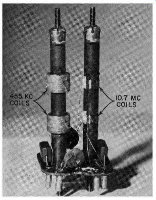
Fig. 7.8. Internal construction of an AM, FM, I.F. transformer. The
capacitors at the bottom are connected across the coil windings.
In order to enhance the sales value of FM receivers (due to its present restricted use), it is common practice to provide for the reception of standard broadcast stations. To keep the total cost of the receiver at a minimum, the same tubes are used for all frequencies, each band corresponding to a different position on the selector switch. One I.F. is employed for the FM band and one set of I.F. coils for the standard broadcast band. To keep connecting wire lengths to a minimum and for space economy, both I.F. transformers are placed within the same can.
In essentially all recent constructions, each set of I.F. coils is mounted on a separate hollow post. Inside each post there are two separate iron cores, one adjustable from the top of the can, the other from the bottom. In addition, the fixed capacitors which resonate each coil winding are also placed within the housing can in order to form as compact an assembly as possible. (See Fig. 7.8.) No difficulty is encountered by placing the transformers in series with each other, as shown in Fig. 7.6. At any one time only one signal is being received and therefore only one set of I.F. transformers is in use. If the signal is AM, the lower set of I.F. transformers in Fig. 7.6 is being used.
The upper transformers which are in series with the AM units do not affect the AM signal because the inductance in the 10.7 mhz coils is almost negligible at 455 khz.
When an FM signal is being received, the upper set of I.F. transformers are used. The 455 khz units do not affect the FM signal because the capacitor shunting the 455 khz I.F. windings acts as a short circuit to the higher 10.7 mhz signal, effectively permitting the 10.7 mhz signal to pass through the series 455 khz units with negligible loss.
EXAM
1. What purpose do the I.F. amplifiers serve in a super heterodyne?
2. What advantages are obtained through the use of an I.F. amplifier?
3. What three basic factors must be considered in the design of an I.F. amplifier?
4. Define spurious responses.
5. Which spurious responses prove most troublesome to FM reception?
6. What governs the choice of an intermediate frequency?
7. Explain image response. Is this phenomenon present in AM receivers? Explain.
8. What effect does image response have on the choice of an intermediate frequency?
9. How can image response be minimized?
10. How can stations separated in frequency by an amount equal to the receiver I.F. cause interference?
11. What solutions can be employed against this type of interference?
12. What do we mean by the phrase "harmonic spurious responses"? What can be done to reduce their effect?
13. Define the phrase "selectivity of a receiver"? Why is this important?
14. Are the gain and the selectivity of a receiver related? How?
15. What is the difference between the ideal response of a tuning circuit and its actual response? Illustrate by means of graphs.
16. Can interference destroy the desired signal in an FM receiver? Explain.
17. What relationship exists between the gain of a tuned circuit and the Q of the same circuit?
18. What tends to lower the Q of a tuned circuit?
19. What do we mean by the "Figure of Merit" of a tube? How does this factor influence the design of an I.F. amplifier?
20. Draw a tube symbol and indicate the various capacitances associated with the tube.
21. How is the "Figure of Merit" of a tube obtained?
22. Draw the schematic circuit of an I.F. amplifier.
23. How is one I.F. system used in receivers capable of receiving AM and FM signals?
24. What types of interstage coupling are found in the I.F. amplifiers of an FM receiver?
25. How are most I.F. stages tuned? Why?
+++++++++++