THE oscillator operates only when the tape recorder is in the record mode and usually has a double function-to provide bias current to the record head and erase current to the erase head.
In recorders using a permanent magnet for erase or in special machines such as duplicators, where erasure is not needed, the bias function alone is performed.
Bias current is fed into the record head along with the audio signal current and serves two vital purposes. It increases the amount of signal which is recorded on the tape. At the same time, for a given level of recorded signal, it reduces distortion. Unfortunately, there is the disadvantage that, as bias current is increased above a certain point, high frequency response deteriorates. At the commonly used speeds of 15, 7.5, and 3.75 ips, the bias required for minimum distortion entails very substantial losses in the amount of high frequency signals recorded on the tape. The slower the tape speed, the greater are the treble losses.
Bias current requirements of record heads are usually fairly modest, on the order of 1 ma for many heads. In contrast, a typical erase head requires much more current to perform its function properly. Erase current may range from something like 15 ma to many times this amount.
Oscillator operation
The purpose of the grid resistor R and grid capacitor C2 in Fig. 801 is to provide the oscillator tube with the required negative grid bias. The amount of grid bias depends upon the magnitude of oscillation required-within the tube's capabilities. When the grid goes positive and draws current, the resulting electron flow charges the top of the capacitor. The only path for the capacitor to discharge is through the grid resistor. As electrons leak slowly from top to bottom of the capacitor through the resistor, this flow causes a negative dc voltage to appear at the top of the resistor.
This voltage also appears at the control grid.
The negative grid leak bias reduces the transconductance (gm) of the tube, hence the gain around the complete oscillation loop.
If the loop gain is greater than 1, as it must be for oscillation to start, the amplitude of each successive oscillation will be greater than the previous one. This causes the grid to swing more into the grid current region on each positive half cycle, resulting in more grid leak bias. But the bias affects the transconductance very markedly: the greater the negative bias, the lower the transconductance.
So each positive grid swing results in added negative bias, reducing the transconductance, hence the gain, until the loop gain is exactly 1. The amplitude of the oscillations will remain at this value very closely. Suppose some disturbance occurred which would increase the amplitude of oscillation. For example, if the ac line voltage rose a few volts, increasing the B plus supply and heater voltages, immediately the amplitude of the positive (and negative) grid signal swings would increase, the number of electrons striking the grid would increase, the grid leak bias would become more negative and the gm and gain of the tube would decrease, bringing the amplitude of the oscillations close to their original value.
Most oscillators employed in tape recorders operate by applying positive feedback between appropriate tube elements, usually between plate and grid, in an amount sufficient to sustain oscillations in a tuned circuit consisting of a coil and capacitor. The values of the coil and capacitor essentially determine the frequency of oscillation.
The operation of a tuned-circuit oscillator is a complex process, with many things happening at the same time. A complete description requires tracing over one cycle of oscillation the phase relationships between voltage and current in electromagnetic and electrostatic fields and in a tube circuit. While space does not permit such a step-by-step analysis for the more common oscillator circuits, an attempt will be made to provide a basic insight into how they work.
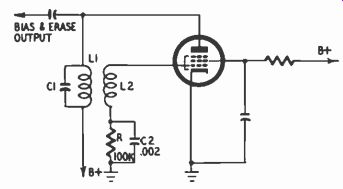
Fig. 801. Single-ended oscillator, employing plate-to-grid feedback.
A fundamental explanation can be based around Fig. 801, which shows a simple oscillator, similar to that found in many moderate-price tape recorders. To help understand why oscillation takes place, it is helpful to consider just the tuned circuit, comprising C1 and L1. Assume that for some reason the tipper plate of C1 is charged, that is, contains more electrons than the lower plate. Seeking equilibrium, electrons tend to flow from the upper to the lower plate through the path afforded by L1. This flow creates an electromagnetic field about the coil and, by Lenz's law, induces a voltage across the coil in a direction such as to pre vent electrons from flowing rapidly through the coil. Thus the electron flow gradually reaches a maximum and then starts to slow down as the charges on the upper and lower plates approach equilibrium. However, when the rate of discharge of electrons from the upper to the lower plate begins to slow down, the field of L1 begins to collapse. By Lenz's law, a voltage is again induced which opposes the change in electron flow through the coil. Thus the collapsing field promotes the continued flow of electrons from the upper to the lower plate. In this manner the lower plate collects not just enough electrons to restore equilibrium with respect to the upper plate (zero voltage across the capacitor); rather it accumulates an excess of electrons compared with the upper plate.
Eventually the coil's field has fully collapsed so that no more electrons arrive at the lower plate. Now this plate has an excess of electrons (in other words, the capacitor has an electrostatic field, which is the counterpart of the coil's electromagnetic field).
Therefore, electrons begin to flow from the lower to the upper plate through the coil. As before, an electromagnetic field is built up around L1 and, when this field collapses, it results in the continued accumulation of electrons on the upper plate of C1 so that the original state of matters is restored: an excess of electrons on the upper plate. This completes one cycle of oscillation.
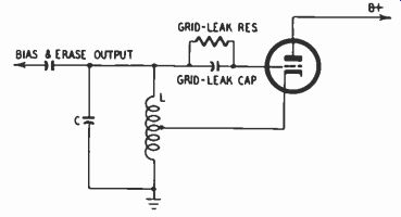
Fig. 802. Single-ended oscillator employing cathode-to-grid feedback.
Assuming no resistance in the coil and no load, the tuned circuit produces a perfect sine wave, eminently desirable for tape recording purposes to achieve a minimum of noise. In practice, this is, of course, impossible; some distortion is always present.
The frequency of oscillation--or the time required for one cycle--essentially depends upon the values of L1 and C1 (to some extent it is also governed by the slight amounts of inductance and capacitance found in the tube and other components associated with the tuned circuit). The coil and capacitor values, in conjunction with each other, determine how long it takes for the electromagnetic field of L1 to build up and collapse and for the electrostatic field of C1 to build up and collapse. The larger the inductance of L1, the longer its field takes to grow and fall. Similarly, the larger the capacitance, the longer it takes to discharge electrons from one plate to the other. At the oscillation frequency, the charge or discharge rates of the two components are equal and work in unison: the electromagnetic field stores energy for the same period that the capacitor is able to deliver it and then, in turn, the capacitor stores energy for the same period that the coil is able to deliver it.
Another way to appreciate why a circuit such as Fig. 801 oscillates at one particular frequency is to consider the impedance be tween the plate side of the tuned circuit and ground. (It should be recognized that the bottom of the tuned circuit is effectively at ground so far as ac is concerned because of the filter capacitor always associated with B plus.) Maximum impedance of the tuned circuit occurs at the frequency where the reactances of L1 and C1 are equal. For any other frequency, the impedance is less so that either the coil or capacitor tends to serve as a shunt to ground. Consequently, alternating current developed through oscillation tends to be shunted to ground except at the frequency where the impedance is maximum.
Once started, oscillation in a tuned circuit would theoretically continue forever were it not for various losses, including those due to resistance in the coil, leakage in the capacitor and the load presented by the tape recorder heads and other circuit elements. For oscillation to be sustained, the tuned circuit needs outside aid.
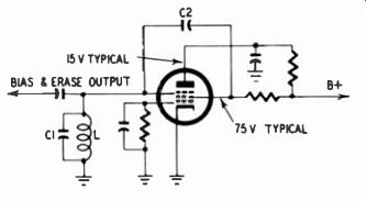
Fig. 803. Single-ended oscillator employing the transitron principle.
This is similar to the case of the child on a swing, who keeps moving as the result of a moderate systematic push from someone on the ground.
The tuned circuit receives systematic aid from the tube circuit with which it is associated. When the upper plate of C1 is to be charged, matters are arranged (as indicated in the next paragraph) so that tube current increases, thereby sending more electrons to this plate. Conversely, when the lower plate of C1 is being charged, tube current decreases, sending more electrons to this plate (from the viewpoint of ac, a decrease in tube current is in effect a flow of electrons from B plus toward the tube).
The purpose of L2 in Fig. 801 is to vary the grid voltage in a manner which causes tube current to assist the oscillation process.
The changing electromagnetic field of L1 cuts across L2 and, by transformer action, induces a voltage across L2--that is, between grid and ground. The windings of L2 are so connected to grid and ground that, when tube current is increasing, the grid end of L2 goes positive, which causes a further increase in tube current. This, of course, is positive feedback. Similarly, when tube current is decreasing, the grid goes negative, resulting in a further reduction in tube current.
The cumulative increase or decrease in tube current which takes place due to positive feedback approaches an end when the charge on either plate of C1 approaches maximum. There is a slowing collapse of the magnetic field around L1 and eventual reversal of this field as C1 approaches maximum charge and then begins to discharge. This results, through transformer action, in a decrease in grid voltage (positive or negative as the case may be) and eventual reversal of its polarity.
Though belated, an explanation of how oscillation gets started is now appropriate. Assuming that B plus has been applied to the circuit and current supplied to the tube heater, initially there is zero voltage between grid and cathode. Due to the random motion of electrons emitted from the cathode, a minute voltage will appear at the grid. Assume that at a given instant this voltage is positive-going. Therefore the current through the tube increases.
This increase in tube current results in a charge on C1, a change in the electromagnetic field of L1, positive feedback at the grid, a further increase in tube current--and the process of oscillation is on, as already described.
Although grid-leak bias keeps the amplitude of oscillations from being extremely high, it is very desirable that feedback be limited so that the tube operates within the linear portion of its characteristic in order to maintain an oscillation waveform with minimum harmonic distortion. In the case of Fig. 801, feedback is controlled by using a proper ratio of turns and the right amount of coupling between L1 and L2, thus limiting the voltage fed back to the grid. Ideally the tube operates class A, in the linear range of its characteristic, though occasionally the higher output capabilities of class B or class C operation are necessary, with attendant higher distortion. A more conservative choice of circuit or tube is not always economically feasible.
There are a number of variations of the single-ended oscillator of Fig. 801, most of which rely on positive feedback. In some instances the oscillator coil is in the grid-cathode circuit, as in Fig. 802. For positive feedback to occur here, it is necessary that the grid go positive relative to the cathode when tube current in creases, and negative when current decreases. Positive grid-cathode voltage, in turn, increases tube current, and negative grid cathode voltage decreases it. The cumulative buildup or decrease in tube current is controlled by the tuned circuit so as to sustain oscillation.
Assume that the current flowing from ground through the lower part of oscillator coil L and then through the tube is momentarily increasing. This increasing current induces a voltage across the grid-ground portion of the coil such as to oppose the increase. That is, the inductive reactance of the coil causes a voltage drop across it, causing the cathode end to go positive with respect to the ground end. By autotransformer action, the positive-going voltage at the cathode appears as a still more positive voltage at the grid, causing a further increase in tube current.
Thus, as in the case of Fig. 801, positive feedback is present. The voltage between grid and ground causes the capacitor C to charge, makes the grid end positive and the ground end negative. Since the tube current cannot increase without limit, the tube current eventually reaches a maximum, that is, a steady value. As a result there is no longer an induced voltage due to tube current increasing. Consequently the grid to ground, voltage decreases and capacitor C discharges upward through the coil.
As the grid to ground voltage decreases, the grid to cathode voltage decreases and the tube current decreases also. This induces a voltage in the lower portion of the coil, this time negative at the top and positive at the ground end. As before, autotransformer action causes the grid to go more negative with respect to the cathode, further reducing tube current, making the grid still more negative, and thus assisting the upper plate of the capacitor to go negative with respect to the lower plate. It should be kept in mind that the process of positive feedback and the turning points from increasing to decreasing tube current are under control of the tuned circuit, which determines the rate of increase and decrease in tube current and thus the frequency of oscillation. Finally, it may he pointed out that while the locations of the grid-leak resistor and capacitor are different in Fig. 802 than in Fig. 801, the action is exactly the same.
The self regulation of the grid-leak bias system is not perfect, of course, but is sufficient to make the oscillator relatively insensitive to line voltage variations, changes due to normal heating of the components, and tube aging.
The grid capacitor loses some of its charge during every cycle but unless the oscillations are getting smaller, each positive grid swing will recharge the capacitor, thus maintaining the bias voltage. The time constant of the grid-leak capacitor and grid resistor (product of R times C2) determines how long the capacitor can discharge through the resistor before the voltage has dropped appreciably. It should be roughly 5 to 10 times the period of one cycle of oscillation to maintain grid bias adequately. For example, if the oscillator frequency is 50,000 hz per second, one cycle is 1/50,000 second, or 20 microseconds (pm); 10 times this amount is 200 psec. The time constant of the 100,000-ohm resistor and 0.002-u-f capacitor in Fig. 801 is 200 u-sec.
Occasionally encountered in tape recorders is the "transitron" circuit, which does not depend upon positive feedback, as the majority of oscillators do. This is illustrated in Fig. 803. Its operation can be explained by first assuming that random electron motion causes a slight increase in cathode current. Some of the electrons strike the screen, causing the screen voltage to decrease.
This negative-going voltage is transferred by C2 to the suppressor grid, charging C1. The major portion of the electrons leaving the cathode go through the screen but, when they approach the suppressor, they are repelled. Normally they are repelled toward the plate but in this case the plate voltage is so much lower than the screen voltage and the suppressor is so negative that the electrons are driven back to the screen, causing the screen to go still more negative. This process builds up (but is eventually reversed because of the action of L and C1 which produces a sine-wave fluctuation) until the screen current approaches saturation.
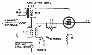
Fig. 804. Use of the audio output tube as an oscillator in the record
mode.
The large majority of moderate-price tape recorders contain a small speaker and a power amplifier, usually single-ended, for playback purposes. As a measure of economy, a number of these recorders convert the audio output tube to an oscillator in the record mode. In a few instances, a similar double function is served by other tubes. For example, in one recorder the playback input stage becomes an oscillator when recording.
Fig. 804 shows a circuit in which the audio tube doubles as an oscillator. L1 and L2 constitute the oscillator coil, providing plate-to-grid feedback. The primary of the audio output transformer is in series with L1. Capacitor C2 across the output trans former primary offers a low-reactance path at the oscillator frequency between the plate of the tube and the primary of the oscillator coil. Similarly, L1 of the oscillator coil offers a low-reactance path at audio frequencies between B plus and L3, the output transformer primary. It may be noted that the grid-leak resistor and capacitor combination, R-C3, is between the top of L2 and the grid instead of between the bottom of L2 and ground, as in Fig. 801. The grid-leak action is the same in either case.
Push-pull oscillators
The great majority of professional tape recorders and a fair number of moderate-price ones employ a push-pull oscillator, using two triodes or, customarily, two halves of a dual triode.
While one triode is in the positive half of its oscillation cycle, the other is in the negative half. Thus, symmetrical forces are at work, tending to reduce even-harmonic distortion.
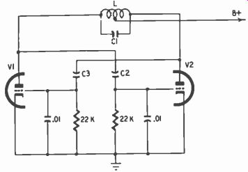
Fig. 805. Typical push-pull oscillator. Oscillator frequency typically
30,000 hz.
Distortion in the bias waveform is a source of noise. Moreover, the greater the demands upon the oscillator to provide enough current for adequate erasure, the greater is the likelihood of distortion. Because of its lower distortion for the same output, the push-pull oscillator is favored in professional machines.
Fig. 805 shows a typical oscillator of this kind. Feedback is from the plate of V1 to the grid of V2 through capacitor C2; and from the plate of V2 to the grid of V1 through capacitor C3. C1, as well as C2 and C3, together with coil L, essentially determine the resonant frequency.
Assume the grid of V1 is positive-going at a given instant. This produces a negative-going voltage at the plate of V1, which is transferred to the grid of V2, causing the plate of V2 to go positive. The voltage fed from the plate of V2 to the grid of V1 is therefore of the same polarity as the original signal on this grid; feedback is positive. The same is true for the voltage fed from the plate of V1 to the grid of V2. However, the voltages on the grids of V1 and V2 are of opposite polarity so that one triode is in the positive half-cycle while the other is in the negative half.
B plus is supplied to the plates of V1 and V2 through the center-tapped coil L. The grid resistors and grid capacitors of each triode produce a negative dc bias in the same manner as explained in connection with Fig. 801.
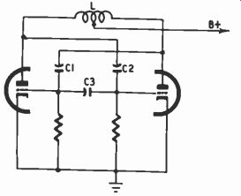
Fig. 806. Variation of the push pull oscillator. C3 is appreciably larger
than C1 and C2.
The feedback capacitor of each triode forms a voltage divider in conjunction with the grid capacitor. Voltage-divider action limits the amount of feedback to the grid, preventing the tubes from being driven excessively. In Fig. 805, the 0.01 u-f grid capacitor has a reactance much smaller than 22,000 ohms at the bias frequency, roughly 50,000 hz, so that the voltage divider consists principally of the feedback and grid capacitors.
There are a number of variations of this basic push-pull circuit. One with several features of interest appears in Fig. 806.
There is no separate resonating capacitor such as C1 in Fig. 805. Instead, the resonant frequency is determined by L and the feed back capacitors C1 and C2, which are linked by the relatively small reactance of C3. C1 and C2 are thus effectively in series with each other and in parallel with the oscillator coil. It will be noted that separate grid-leak capacitors do not appear in Fig. 806.
Instead, capacitors C1 and C2 perform an additional task, acting to maintain negative bias at each grid. The voltages appearing at the grid ends of C1 and C2 vary between zero and some negative value. The grid voltage cannot go above zero because the resultant grid current charges the grid capacitors negatively at the grid side.
Thus a negative charge is built up on the grid side of each capacitor.
Often, to supplement the dc bias obtained by grid-leak action, cathode bias is also used. That is, instead of connecting the cathodes of the triodes directly to ground, they are both connected to ground through a common resistor with a value of several hundred or a few thousand ohms.
Coupling the oscillator to the heads
To couple the oscillator effectively to the record and erase heads, it is necessary to consider the requirements of the oscillator as well as the heads.
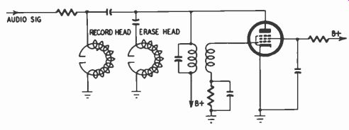
Fig. 807. Direct coupling of the oscillator to record and erase heads.
The voltage across the oscillator coil varies directly with the Q of the resonant circuit. Without a load, the Q of the parallel inductance and capacitance depends almost entirely upon the ratio of the coil's reactance to its resistance at resonance. The Q is reduced by any load presented to the oscillator; say by the heads.
The greater the loading (the smaller the resistance in parallel with the tuned circuit), the smaller is the Q, therefore reducing oscillator output voltage and very likely increasing the distortion.
Moreover, the lower the Q, the less exact is the frequency of oscillation. Thus slight changes in the gain of the tube or in B plus voltage can have an appreciable effect upon frequency.
Coupling circuits, such as a small capacitor, are often affected by frequency and a shift in frequency of oscillation accordingly impairs performance.
From the viewpoint of the heads, the oscillator must provide sufficient voltage to cause the required current to flow through them. The voltage directly available at the oscillator, say at the plate in the case of a single-ended oscillator such as in Fig. 801, may be sufficient to drive the heads, or it may be too much or too little. Where the voltage is insufficient, transformer coupling is often used; a winding on the oscillator coil steps up the available voltage to the required amount.
As a result of the dual need to avoid undue loading of the oscillator and at the same time supply proper current to the heads, one finds many variations in coupling. Moreover, because of the different requirements of the record and erase heads., one often finds the oscillator current coupled to the record head in one fashion and to the erase head in another.
Considering single-ended oscillators first, Fig. 807 illustrates the use of direct coupling to both the record and erase heads.
The value of the coupling capacitor and the inductance of the head determine the amount of current flowing through each head.
A resistor is used to prevent the audio source from adversely affecting the oscillator circuit. The typical "constant current" resistor described in Section 4 serves admirably. Because of its high reactance even at the highest audio frequencies, the bias coupling capacitor prevents the oscillator coil from shunting the audio current around the record head.
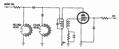
Fig. 808. Alternate method of direct coupling to reduce loading effect
upon the oscillator.
Fig. 808 is a variation of Fig. 807, the only difference being that oscillator voltage is taken from a tap on the primary of the coil instead of at the top of the coil (plate of the tube). The reason for doing so is to reduce the loading effect of the heads upon the oscillator. Obviously, if the connection were made at the bottom of the coil, there would be no loading whatsoever (and no voltage to the heads), whereas the top connection represents maxi mum loading (and maximum voltage). An intermediate position reduces loading and at the same time permits adequate voltage to be applied to the heads. The primary of the oscillator coil is de signed with the tap properly located to apply the required voltage to the heads.
A quite popular method of coupling a single-ended oscillator to the heads is illustrated in Fig. 809. Here a tertiary winding is employed which serves both to isolate the heads from the oscillator coil and at the same time provide them with the required voltages.
In the case of push-pull oscillators, the record head is seldom directly coupled to the oscillator coil, although there are exceptions. Record heads are ordinarily unbalanced, one end of the winding being connected to ground. Direct coupling would load down one triode and not the other, impairing the all-important symmetry of the oscillator. Therefore, as a rule, a secondary winding is used for coupling the oscillator current to the record head (Fig. 810). The secondary also supplies current to the erase head.
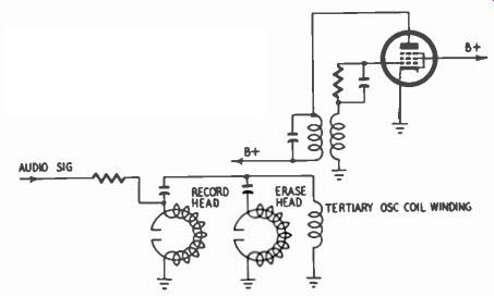
Fig. 809. Transformer coupling of the oscillator to re cord and erase
heads.
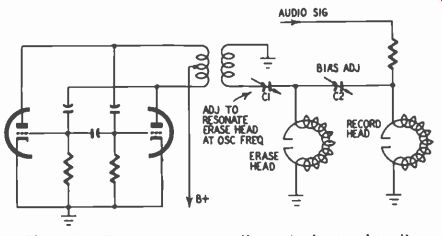
Fig. 810. Transformer coupling of the push-pull oscillator to unbalanced-heads.
Because of the relatively high impedance of the erase head at the bias frequency, a substantial voltage must be generated by the oscillator to drive sufficient current through the head. How ever, the required voltage can be reduced by utilizing a series-resonant circuit, as shown in Fig. 810. If the capacitor and head inductances resonate at the oscillator frequency, the series impedance of these components is at a minimum and a relatively low voltage will cause adequate current to flow throughout the erase head. The same principle can be employed for single-ended oscillators (Fig. 809) where the capacitor in series with the erase head can be selected to resonate with the head at the bias frequency.
Returning to Fig. 810, let us consider the needs of the record head with respect to bias current. Current demands are much smaller for bias than for erase, and at the same time the impedance of the record head is generally greater than that of the erase head, so a substantial driving voltage is still necessary for the record head. It may be, therefore, that the voltage across the secondary of the oscillator coil is insufficient to meet the bias current needs of the record head. This high voltage can be obtained across the erase head itself (Fig. 810). Although the voltage across the head and capacitor in series is low, that across the head alone is much higher (voltage equals reactance times current).
Whereas the erase head in Fig. 810 is shown connected to ground, it is feasible to couple it directly to the plates of the oscillator triodes, as illustrated in Fig. 811. Voltage for the record head, however, is still taken from a secondary winding on the oscillator coil.
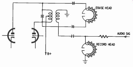
Fig. 811. Direct coupling of the push-pull oscillator to the erase head.
It may be questioned why coupling capacitors are used for the balanced line connection to the erase head in Fig. 811. Apparently, since the triode plates are theoretically at the same B-plus voltage and the primary has practically no dc resistance, there is no dc across the primary coil. Such dc would produce modulation noise on the tape as well as magnetize the head, thereby producing further noise. However, any unbalance in the oscillator would cause dc to flow through the erase head so that the coupling capacitors, although theoretically unnecessary, do offer a practical safeguard.
Fig. 812 presents one of the rather rare instances in which direct coupling is used with a push-pull oscillator for both the record and erase heads. For the erase head, direct coupling presents no symmetrical loading problem because this head is not connected to ground. In the case of the record head, however, which is of the usual unbalanced type, direct coupling does tend to upset the symmetry of the oscillator by loading V1 and reducing its output.
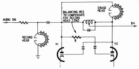
Fig. 812. Direct coupling of the push-pull oscillator to both heads.
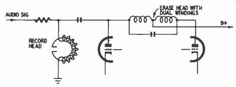
Fig. 813. Use of the erase head as the coil in a push-pull oscillator.
However, resistor R compensates by loading V2, so that the out put of V2 is reduced more or less to the same extent as V1.
Fig. 813 is somewhat similar to Fig. 812 but here the circuit is further simplified by having the erase head act as the oscillator coil. The head has two windings whose junction serves as the center tap. Since the dc plate currents flow through the erase head in opposite directions, theoretically no net dc should flow through the head. Bias current for the record head is taken from one of the triode plates but in this case no attempt is made to compensate for the resulting unbalance in the circuit. The record head of this particular machine has quite a high impedance. Its loading effect is therefore rather small and the amount of un balance caused in the oscillator is slight enough so that quality of performance is consistent with that which can reasonably be expected of a tape recorder in its price class.
Most commonly, bias current is supplied straight to the record head, along with the audio signal, as shown in Figs. 807, 808, 809, etc. In a few instances, because of the type of oscillator tube and circuit used, not enough high-frequency voltage is developed to meet the needs of the record head. Therefore the bias is mixed with the audio signal prior to the stage that drives the record head (Fig. 814). This stage provides the necessary amplification.
Control of bias current
The exact amount of high frequency current going through the erase head is not too important as long as there is enough to saturate the head without heating it to excess. Once the head is saturated, it is doing as good a job as its size and design permit.
Further increases in current produce no significant improvements in erasure. The amount of bias current supplied to the record head is an altogether different matter. As indicated in the early part of this section, bias affects distortion and frequency response.
Slight changes in bias produce relatively large variations in distortion and in treble response.
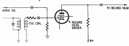
Fig. 814. Mixing of the audio signal and bias current prior to the record-head
driver.
The optimum amount of bias current is that which reduces distortion to the fullest extent compatible with adequate high frequency response and a satisfactory signal-to-noise ratio. Optimum bias current, particularly at tape speeds below 15 ips, varies with the manufacturer's or user's concept of an acceptable limit to high-frequency response. At 7.5 ips, some may consider nothing less than response flat to 15,000 hz as acceptable while others, in exchange for lower distortion and/or higher signal-to-noise ratio, may be willing to settle for a fairly flat response to 12,000 or even 10,000 hz. Thus, the decision as to the optimum combination of high-frequency response, distortion and signal-to noise ratio determines the specific amount of bias current de sired. It should be taken into account, furthermore, that this specific value varies somewhat from one brand of tape to another and from one kind of tape to another (regular versus high output).
In view of the critical nature of the amount of bias used, together with the fact that the optimum value varies among tapes, it is highly desirable, where the utmost in recording quality is sought, to provide some means for varying bias current. This the professional tape recorders do almost without exception. A few of the moderate-price ones do also. Sometimes the bias control is intended only for factory adjustment and is mounted fairly inaccessibly inside the tape amplifier. In other instances it is made readily available either at the rear panel of the amplifier, above chassis or even on the front panel. On the other hand, some mechanical safeguard has to be provided against accidental disturbance of the optimum setting; for example, the control shaft may be recessed behind a hole and require a screwdriver for adjustment.
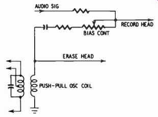
Fig. 815. Control of bias by a variable resistance.
One method of varying bias current is to place a variable resistor between the bias supply and the record head. The disadvantages of a potentiometer. however, are that it is apt to become noisy in time and dissipates power because of current passing through a resistance. This consumption of power places an extra burden on an already hard-working oscillator.
Use of a variable series capacitor instead of a resistor has the advantage of not absorbing power. But there are drawbacks, too.
The variable capacitor is usually of the mica compression type, with air and mica serving as the dielectric. Its open construction makes it vulnerable to heat, humidity and dust, all of which tend to cause changes in capacitance after the optimum setting has been determined. Furthermore, a series capacitor discriminates more against the fundamental of the bias frequency than against its harmonics so that the effective harmonic distortion of the bias frequency is increased, resulting in greater recorded noise than if the fundamental and harmonics were passed to the same ex tent. (Although a variable inductor could be used instead to discriminate against harmonics, the extra expense and shielding problems of a coil generally militate against this expedient.)
While the proper choice of bias current control depends upon the particular circuit employed, on the whole the most satisfactory method is provided by the series potentiometer. Its range of control should be limited by making the potentiometer only part of the total series resistance, as illustrated in Fig. 815. This has two advantages (1) It prevents supplying an excessive amount of high-frequency current to the record head, possibly resulting in injury to the head through overheating. (2) Since the potentiometer controls only a portion of the total resistance, the amount of adjustment per degree of rotation is small, permitting very precise settings to be obtained easily. Depending upon the amount of current handled, it may be necessary to use a wirewound unit be cause of the larger wattage ratings in which the latter are avail able; but in many cases the less-expensive carbon potentiometer suffices.
To facilitate proper control of bias current, most tape recorders that incorporate a meter for indicating record level also use this meter, through a suitable switch, for measuring bias. Since bias requirements vary somewhat from one brand or kind of tape to another, the experienced user gets to know the proper setting for each tape that he uses. Due to tube and component aging, the output of the oscillator usually tends to drop over a period of time. This decrease may result in gradual deterioration of quality in the recorded tape. The meter immediately notifies the operator of a decline or possible increase in bias. The usual technique of metering bias current is to measure the voltage across a small series resistor between the record head and ground. Erase head current can be similarly metered, although this is seldom done because erase-head current can change over a fairly substantial range without affecting performance.
Drift
As the oscillator warms up, its output tends to change slightly.
The period of drift may last from 15 minutes to 1/2 hour or more.
Professional users allow a liberal amount of warmup time before putting their tape recorders to work to permit the oscillator (as well as other elements of the machine, including the transport) to stabilize.
Bias current flowing through the record head can vary because of changes in oscillator frequency. These frequency changes may alter the output of the oscillator and/or they may affect the coupling between head and oscillator. Furthermore, output of the oscillator may be affected by changes in the value of the load.
Generally, the factors primarily responsible for the change in oscillator frequency are the resonant coil and capacitor. The coil has an inherent positive temperature coefficient: that is, its inductance rises with temperature, reducing the oscillator frequency. The ordinary capacitor also has a positive coefficient, which further reduces the resonant frequency. But capacitors with negative temperature coefficients are available so that a close approach to a stable circuit can be had by using them in the tuned circuit.
Changes in resonant frequency affect the Q of the tuned circuit slightly by altering the coil's ratio of inductive reactance to resistance at the resonant frequency. Increased Q results in greater voltage output by the oscillator tube while reduced Q decreases output.
Other factors responsible to a degree for drift in oscillator out put are temperature effects upon vacuum tubes, upon components which constitute the load on the oscillator, and upon plate voltage variations. Temperature changes cause the spacing be tween tube elements to vary, thereby altering interelectrode capacitances and transconductance. Changes in value of load components, temperature, affect the resonant which in turn governs oscillator output in the manner already described. Variations in plate voltage on the oscillator tube successively affect resonant frequency, Q, and output.
Frequency stability depends substantially upon how sharply the resonant circuit is tuned, which is a function of its Q. A heavy load makes for a broadly rather than sharply tuned circuit and therefore causes the oscillator to be particularly susceptible to frequency drift, which can affect the coupling to the record head.
Apart from the effect upon output, variations in oscillator frequency can change the amount of bias current flowing through the head if a coupling capacitor is used between the oscillator and the head, as is generally the case. Reactance of this capacitor varies with frequency, therefore reducing or increasing bias cur rent flow.
Although the foregoing discussion may cause the oscillator to appear over-susceptible to drift, this is not true for the usual manner in which it is operated in tape recorders. The oscillator, whether single-ended or push-pull, is generally operated with grid leak bias, where the grid voltage goes sufficiently positive on one half of the cycle for the grid to draw current. As already explained, this current develops a negative bias on the grid by means of a grid-leak circuit. The amount of bias varies in a way that makes the circuit substantially self-regulating with respect to output voltage. If for some reason, say a slight drop in B-plus voltage, the oscillator output were to decrease, smaller feedback voltages would appear at the grid, and the grid capacitor would be charged to a lesser extent, resulting in lower grid bias. But a reduction in grid bias increases the transconductance of the tube, increasing the output. This, then, makes for a self-regulating circuit, tending to produce relatively constant voltage, independent of such factors as heater voltage, B-plus supply voltage, tube aging, load on the oscillator, etc.-within reason.
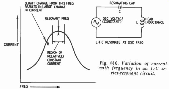
Fig. 816. Variation of current with frequency in an L-C series-resonant
circuit.
By operating the oscillator with self bias and employing such measures as a negative coefficient capacitor in the resonant circuit, oscillator output and therefore bias current can be made relatively stable. A further means of limiting bias current drift to a minimum is to resonate the record head with a series capacitor at the oscillator frequency. In an L-C series resonant circuit, current depends upon frequency in the manner of Fig. 816. Current varies sharply with slight changes in frequency, except in the peak region, where there is somewhat of a plateau. Thus, if the oscillator frequency drifts slightly in the region of resonance (point A), the effect upon bias current is insignificant whereas, if it drifts in a region well-removed from resonance (point B), the effect upon bias current is pronounced.
Waveform
Optimum performance requires that the oscillator produce a perfect sine wave. Odd- and even-harmonic distortion components, inevitably present to some degree, cause noise to appear on the tape. The principal offender appears to be second harmonic distortion.
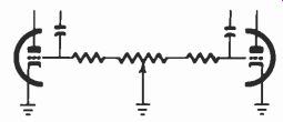
Fig. 817. Use of a balancing control in a push-pull oscillator to reduce
noise.
For low harmonic-distortion content, it is necessary that the tuned circuit have a high Q. The action of the tuned circuit may be likened to that of a flywheel, converting periodic bursts of cur rent from the oscillator tube (or tubes in the case of push-pull) into a steady sinusoidal current. In fact, this property of the L-C circuit is often called the "flywheel effect." The higher the Q, the purer the waveform. A Q of about 10 is considered sufficient for providing fairly distortion-free current.
The Q is affected by the load on the oscillator. The load on the oscillator consists partly of current drawn by the heads and partly of current drawn by the grid on positive pulses. Excessive grid current, caused by either too much feedback or too low a value of grid-leak resistor, reduces the Q and in turn causes distortion to rise.
The push-pull oscillator can theoretically effect complete cancellation of second- and other even-harmonic distortion. Cancellation depends upon the degree of balance between the two halves of the oscillator circuit. Perfect balance requires that the trans-conductances of the two triodes be equal, that the tuned oscillator coil have an accurate electrical center tap, that the grid resistors and the feedback capacitors be matched. By using a dual triode such as the 12AU7 or 12BH7 the requirement of matched tubes can be satisfactorily met. Components with 5% tolerances meet the resistor and capacitor requirements adequately.
To insure symmetry between the two halves of a push-pull circuit, means are sometimes provided for balancing the triodes (Fig. 817). The grid resistors are connected to the outer terminals of a potentiometer, with the arm to ground. By adjusting the arm, the grid resistance of each tube is changed, which alters the grid bias and therefore the transconductance of the tube. If the tape recorder has separate record and playback heads, balancing can be done by ear; that is, by adjusting the control for minimum noise as heard in playback, without any audio signal fed into the recorder. Distortion can also be checked by using a bridged-T filter to remove the fundamental, leaving the harmonics to be measured.
Harmonic content of 1% or more can be a serious source of noise.
A series capacitor can be used to resonate the record head and thereby stabilize the amount of bias current flowing through it.
Another advantage of this scheme is that of discriminating against harmonics of the bias current. Bias current through the head is maximum in the region of the fundamental oscillator frequency.
At the second and higher harmonics, therefore, considerably less current reaches the head.
Although all the precautions indicated may have been taken, there can still be excessive harmonic distortion, particularly second-harmonic, for absolutely top-notch recording requirements as in a professional studio. Therefore, a filter is sometimes in stalled to suppress the second harmonic specifically.
Fig. 818 is an example of a trap designed to shunt the second harmonic of the oscillator frequency to ground. L1 and C1 are tuned to the second harmonic. R controls the amount of bias current. As shown by curve 1, the inductance of the head produces a 6-db-per-octave rolloff in bias current. L1-CI puts a deep notch in this characteristic at the second harmonic, as shown by curve 2.
As for higher harmonics, three factors account for only minute quantities of these flowing through the record head: (1) the inductance of the head causes a 6-db-per-octave rolloff with increasing frequency; (2) the level of the higher harmonics is initially weaker than that of the second harmonic; (3) reactance of stray capacitance decreases with rising frequency, eventually shunting the upper harmonics around the head.
The purpose of C2 in Fig. 818, a relatively small capacitor, is to prevent the audio signal to the record head from being shunted to ground through R and the oscillator coil.
Frequency
To prevent perceptible beats between the bias current and harmonics of the audio signal, the oscillator frequency should preferably be at least five times the highest recorded audio frequency. But this conflicts with what is best for the erase head.
Since it is common practice to employ one oscillator to supply high-frequency current to both the erase and record heads, the oscillator frequency is often reduced by way of compromise. Thus, it is commonly found in recorders of good quality, which provide response out to 15,000 hz or so at 7.5 ips, that the bias frequency is closer to 50,000 hz than the preferable 75,000. On the other hand, in a number of top-quality recorders no such compromise is made and the frequency is kept upward of 75,000 hz.
To drive the required amount of current through the erase head, a relatively high voltage is needed because the head has considerable reactance at the oscillator frequency. Were the frequency lower, the reactance of the head would be smaller and the voltage demand upon the oscillator would be less. On the other hand, there is the conflicting requirement that the erase head must put each particle on the tape through several complete magnetic hz while the particle is within range of the head's magnetic field. Therefore too low an oscillator frequency is not desirable.
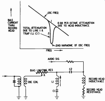
Fig. 818. Use of an L-C trap to reduce second harmonic distortion in
the bias waveform.
In summary, the erase head is best served by a frequency high enough for effective erasure yet low enough to make modest voltage demands on the oscillator.
In a few recorders, particularly of earlier years, the requirements of the erase and record heads are individually satisfied by employing separate oscillators, thus making different frequencies as well as amounts of current readily available. In at least one unit, although only one oscillator was used, different frequencies were obtained by supplying current at the fundamental frequency to the erase head and using the third harmonic for bias current.
A transformer, with the primary connected between the cathode of the oscillator and ground, was tuned to the third harmonic.
This signal was then amplified and fed to the record head.
Stray pickup
If the oscillator frequency finds its way into the record-level circuit, it will give a false upward indication of record level, resulting in an under-recorded tape and a reduced signal-to-noise ratio. If it finds its way into the record amplifier, it may be amplified along with the audio signal and, perhaps in accordance with the volume control setting, increase or decrease the amount of bias reaching the record head. It may cause other undesirable effects, such as oscillation or blocking of amplifier stages.
The oscillator frequency may find its way into unwanted places through stray capacitance or radiation. The higher the frequency, the greater the extent to which it exhibits radio-frequency characteristics. Therefore, the oscillator coil, the chief source of radiation, must be properly shielded and located as far as possible from circuits where stray pickup may do harm. In some tape recorders a toroidal (doughnut-shaped) oscillator coil is used which theoretically has no external magnetic field. However, toroidal coils are expensive.
To prevent stray pickup of bias voltage, care must be taken with respect to the location and lead dress of vulnerable circuits.
Through radiation, the oscillator frequency may be picked up by open switch terminals not used in the record mode. Unless grounded or otherwise properly terminated, these open terminals serve as antennas for stray pickup.