A designer of a complete audio installation will often have to acquire as complete entities speakers, pickups, microphones and tape recorders. These will be housed in various ways, the methods of doing which are not within the domain of electronics, and are not critical as to performance, although the housing of a speaker is a problem in acoustics. But he will nave to design the amplifier and an amplifier can be designed precisely and absolutely. Its performance can be measured by exact technical procedure. The design of an amplifier is, therefore, an engineering problem.
Design considerations
Many hundreds of different designs have appeared over the years and it is not necessary for the audio hobbyist, technician, or engineer to start from scratch and work the whole thing out from first principles. Nevertheless, unless the general principles are understood and applied, the problem will only be solved, if ever, by trying out circuit after circuit until the desired performance has been secured. This process is not engineering, but its popularity is testified by the constant stream of articles on the subject in technical magazines.
The design must be conditioned by the economic factors preceding the actual technical work. The overriding consideration may be cheapness or it may be the highest possible standard of excellence. The designer of a line amplifier for telephone service will be required to provide an exceptional degree of reliability over a long period, yet may not have to provide an extremely wide frequency response. An audio engineer may have to produce a circuit which will prove the claims of the sales department of a concern offering high fidelity at a low price, when reliability clearly cannot be a first consideration.
These varying requirements cannot be met by the "perfect" amplifier, although in actual fact a nearly perfect amplifier can be designed. Such an amplifier would be much too expensive for most uses. The designer must, therefore, be sure that the prerequisites have been clearly stated before he proceeds with his work.
Given these he should then produce the best possible design for the particular object in view. These remarks may seem common place, but it is rather surprising how often the requirements are only specified precisely after a design has been prepared. The man who wishes to create an amplifier for some particular purpose often finds himself under a grave disadvantage. He may consult the usual works of reference to find out just how to put the circuit together and discover so many alternative ways that he does not know which to choose. Then he reads an article in a magazine, written by someone who obviously has had the same sort of problem confronting him, and supposes that the writer has done his work for him. He tries a hookup and finds that the thing doesn't work. But if it doesn't work, it doesn't mean that the writer's design was imperfect. For an article to appear in a responsible magazine the amplifier had to be made, tested, photo graphed and described with preciseness. When it is copied by the reader, it may be that the copyist's components are all on the edge of the permissible tolerances specified in the original design and the cumulative errors may be enormous. Before such errors can be rectified it is necessary to test the amplifier stage by stage, so investigation of every part of the circuit is a necessary consequence to designing.
An amplifier can be designed exactly by application of the known rules but, before the amplifier can be guaranteed to con form to specifications, it must be ascertained that the constituent parts comply. In view of the high cost of close-tolerance components, it is obviously desirable to evolve a design which is not un duly critical as to values.
The present writer has examined over 150 amplifiers which have appeared on the market during the past six years. They show wide variations in design and reflect the requirements placed be fore the technical staffs of various manufacturers. A general pat- tern emerges from this study, although designers will adopt widely different methods of achieving a precisely similar objective. They cannot all be right, for the best method is the simplest one which will do what is wanted. A multiplicity of tubes is not necessarily a criterion of excellence; rather it may be the reverse by introducing unreliability. A multiplicity of controls may suggest that the ultimate user has a greater opportunity of modifying the performance to suit his particular requirements. But even this can be dangerous, for an unskillful operator may so adjust them that the resulting performance is something that can only bring discredit on the guiltless designer. Controls are certainly needed to adjust volume and tonal balance, particularly in view of what has al ready been stated as to the behavior of the human ear, but excessive control facilities, although perhaps good from the "sales angle," are not necessarily good from the point of view of ultimate performance. See Fig. 201 for one possible arrangement of a typical audio system.
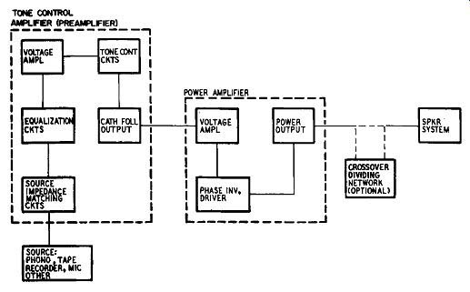
Fig. 201. Block diagram of a typical audio system.
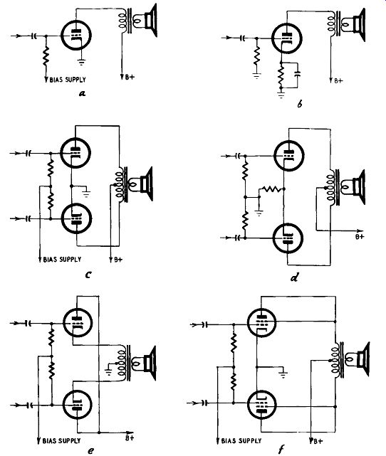
Fig. 202. Representative triode output stages: a) single-ended, fixed
bias; b) single ended, cathode bias; c) push-pull. fixed bias; d) push-pull,
cathode bias; e) cathode follower, push-pull; f) push-pull tetrodes,
triode connected.
Such matters apart, the pattern of the modern amplifier is soon described. The output (power) stage is ordinarily push-pull, some times triodes, more often tetrodes are used; the driver stage is al most equally divided between single and double triodes; phase inversion is rarely by transformer. The preceding voltage amplifier is a triode in the great majority of cases-indeed the pentode seems quite out of favor as an audio amplifier in nearly every position. Tone controls are mostly continuously variable. Except for some bias and plate supplies for separate preamplifier units,tube power supply is invariably drawn from thermionic rectifiers.
Consideration of the relative desirability of these techniques is best divided into sections. Accordingly the design of amplifiers will be treated under various headings: power-output stages; driver stages, including phase inversion; voltage amplifiers, including so-called preamplifiers; tone control circuits; output and other audio transformers; rectifiers and power supply.
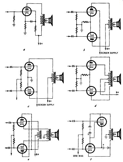
Fig. 203. Representative tetrode output stages: a) single-ended; b)
push-pull, cathode bias; c) push-pull, fixed bias; d) Ultra-Linear; e)
unity coupled; f) fundamental Cirrlotron circuit.
Power-output stages
A power-output stage can consist of a single triode, tetrode or pentode; push-pull triodes, ·tetrodes or pentodes; with or without negative feedback. Except in the cheapest equipment, the single output tube is rare, push-pull operation being almost invariably used. Twenty-five years ago it was not unusual to see triodes used in parallel, obviously to secure greater output power, but as the same two tubes used in push-pull will give even greater power and with less distortion, such applications will not be discussed. See Figs. 202 and 203.
Tubes are paralleled in push-pull stages so as to get greater out put; this doubles, triples or quadruples the power available from a single pair of tubes and is a justifiable expedient when large tubes are not available. In this respect British manufacturers have always had a wider range of power triodes than American. Tetrodes can, of course, be used as triodes, but what the American de signer lacks is a range of large power triodes. Some data on British power triodes are included in Table 6 as a matter of interest. Table 4 includes characteristics of tetrodes when used as triodes.
In the absence of negative feedback, a triode gives less distortion than a tetrode or pentode and has a better damping effect on the reactive load of a speaker. But the distortion from a single triode is substantial at full output and so the single tube cannot be used in better-grade equipment. From the point of view of efficiency, the tetrode is far better than the triode, so if a little more distortion is tolerated in the final design, the single tetrode out put stage is almost universal in inexpensive apparatus. Data for single tetrodes is given in Table 5.
Selecting the tube Of the large number of amplifiers examined, the great majority uses two 6V6 tubes (as tetrodes) in class-AB1 push-pull. Less frequently we find the 6L6 or 5881, also in class AB1; occasionally the 6B4-G (a 6.3-volt-heater octal-base version of the 2A3). As a result of the popularity enjoyed for a considerable time by a certain English circuit the English KT66 is sometimes employed, connected as a triode. One English amplifier available in the United States uses the KT61, connected as a triode. The larger tubes, such as EL34 and 6550 are appearing in more recent de signs. \Ve can now examine the behavior of these various output tubes. Data are given in Table 6 for push-pull triodes and in Table 7 for push-pull tetrodes.
The data is that furnished by tube manufacturers; they are average values, since, obviously, tubes can vary within certain limits. The figures given for power output are always based on the assumption that the load is purely resistive, but when a speaker is used as the load it is both resistive and reactive. This complication will be discussed later.
Tables 4 to 7 are designed to enable the reader to compare performances of various tubes with the minimum of trouble. The facts given are sufficient for designing purposes-a first selection can be made without having to hunt through various tube manuals.
Triodes vs. tetrodes
Used singly, triodes give less distortion than tetrodes but more than is acceptable in high-grade equipment. Triode distortion is mainly second harmonic, which will be cancelled by push-pull operation. Tetrode distortion contains second, third and fourth harmonics. Second and fourth will be cancelled by push-pull working, but not third.
Tube transconductance
The transconductance of the tube is a measure of its grid-voltage-plate-current conversion efficiency but is not of importance except when the minimum number of amplifying stages is demanded on the grounds of cost. In general terms, an output tube with high transconductance requires less input grid swing or plate-supply volts to generate a given amount of audio power than one with lower conductance. In a simple receiver employing the minimum of tubes, the plate-supply voltage is limited and it may be desirable to drive the single output tube direct from the signal rectifier. A tube such as the 50L6 would meet the need, but there is no point in using such tubes in push-pull in more elaborate equipment where voltage amplification can be carried out quite simply.
Tables 6 and 7 show that push-pull triodes do not necessarily give less distortion than push-pull tetrodes, and in some cases are a good deal worse than tetrodes, assuming that the load is purely resistive. For example, push-pull 6L6's with cathode bias deliver 13.3 watts with 4.4% distortion with a plate voltage of 400, when used as triodes. The same tubes as tetrodes in class A1 produce 18.5 watts with only 2% distortion with a plate voltage of 270, or in class AB1, 24.5 watts with 4% distortion with a plate voltage of only 360. Admittedly, the choice is not quite so easy as this, since tetrodes are critical as to the value of load resistance and be cause of their high internal resistance do not offer the same damping to the speaker as triodes. These disabilities can, however, be partially overcome by negative feedback.
Class-AB2 amplification demands fixed bias, but fixed bias gives less distortion, as a rule, than cathode bias. The simplest to provide, cathode bias is in some measure self-compensating for variations in plate supply voltage; but designers of high-grade and efficient amplifiers should avoid the habit of using cathode bias without thinking of the other method.
Power supply stabilization
Class-AB1 (and to an even greater extent with class-AB2) amplification results in wide changes of plate and screen current whether triodes or tetrodes are used. These current changes must not be accompanied by power-supply voltage changes, otherwise the performance deteriorates. Accordingly the supply voltage must re main constant over wide changes of current, and in the case of tetrodes it is highly important that the screen voltage be stabilized.
It is easy and customary to connect the screens of the tubes to the same lines as the plates but this is detrimental to the best results.
The impedance of any speaker varies with frequency and will generally be several times the nominal impedance at high frequencies. This is the part of the frequency spectrum which reproduces the harmonics, so harmonic distortion is basically liable to be severe. If the distortion is further increased by tubes operating away off their normal conditions because of heavy signal inputs, the amplifier ceases to be what the designer intended. Many amplifiers, taking the easy way out, could be improved out of all recognition by having the plate and screen supply voltages stabilized.
Unfortunately, this adds to the cost of the power supply.
A small point can be brought up in assessing the relative merits of various tubes. The KT66 is, in some quarters, regarded as a mysteriously wonderful tube, but this results from a failure to assess all the circumstances. At least as a tetrode, the 6L6 is not safe to use at higher plate voltages than about 385, owing to the design of the glass pinch inside the tube (Table 7 shows that at 250 to 270 volts the 6L6 is actually better than the KT66), but the difficulty can be overcome completely by using the 807, which has the same characteristics as the 6L6, but which can safely be used at voltages up to 600. The KT66 characteristics differ from those of the 6L6, 5881 and 807, but whereas those characteristics may be more suitable in certain cases, it is neither a better nor worse tube than currently available American types. Like the 6L6 it is a pre-World War II design.
Single-triode output stages
The data given in Table 4 represent the normal state of the tube in the absence of signal. Taking the 2A3 as an example, a grid bias of -45 volts suggests the tube can accept a signal input of 45 volts peak ac, which means that the control grid will vary in voltage from 0 to -90. The behavior of the tube under these varying conditions is displayed in a family of plate-current-plate-voltage curves, illustrated by Fig. 204. These curves are typical of those appearing in tube manufacturers' manuals.
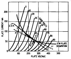
Fig. 204. Plate-voltage-plate-current curves of the 2A3 showing load
line and operating conditions.
Each curve shows the plate current plotted against plate voltage for grid bias at 10-volt steps between 0 and -90 volts (twice the recommended bias). A short curve is drawn representing the specified normal bias for this tube, -45 volts. Also shown is the maximum permissible plate dissipation, 15 watts, a figure which can be checked by referring to the current and voltage values at any point on the curve.
Load line
No tube can be expected to give good life if operated beyond its maximum plate dissipation rating. As a datum point, there fore, we select that point where the -45-volt curve is intersected by the power dissipation curve. Call this point 0. The load line is now drawn; its gradient is determined by the resistance it represents. If a 1ine is drawn joining the points at 250 volts on the voltage axis and 100 ma on the current axis, it would represent a resistance of 2,500 ohms, since:
250 volts / 0.1 amperes = 2,500 ohms
Any line drawn parallel to this line would also represent a resistance of 2,500 ohms, so such a parallel line is drawn through the point 0, marked XOY. This is the load line for a 2A3 with a purely resistive load of 2,500 ohms. This is illustrated in the drawing of Fig. 204.
A peak signal of 45 volts applied to the grid will cause the operating point to move from O to X, back to 0, from O to Y and back to 0, but it will be seen that OX does not equal OY. Be cause of this, distortion will occur for an examination of the figure shows that, whereas a change of voltage on the grid from -45 to 0 produces a voltage change of 150 on the plate, a change on the grid from -45 to -90 volts produces a voltage change on the plate of only 115. Similarly the current change in the first instance is 60 ma, and in the second 46 ma. In the case of triodes this distortion is mainly second harmonic and can be calculated from the formula that is shown below. The power output can also be calculated.
The point X is the point of minimum voltage and maximum current; Y is the point of maximum voltage and minimum current.
Dmax - Imin] [Emax - Emin] Power output = ----------- 8
½ Dmax + Imin] - Io
% 2nd harmonic distortion = --------X I 00 I_max – I_min where I0 = current at the normal operating point 0. In the case illustrated:
[117.5 - 12.5] [370 - 105]
Power output _----------- = 3.478 watts 8
½ [ I I 7. 5 + 12. 5] - 60 2nd harmonic distortion =---------X 100 = 4.76% 105
These figures will be seen to be similar to the data given in Table 4.
Note also that the load line passes above the power dissipation curve in the region between -20 and -40 volts. As this happens only momentarily with any musical signal it is of no consequence, but a tube must never be operated in a steady state beyond its maximum rating.
As a matter of interest, a load line may be drawn which is tangential to the dissipation curve; such is shown, by X'OY'. The gradient of the line is changed and in fact represents a load of just under 4,000 ohms. The power generated is also changed, as is the distortion, the difference between X'O and OY' not being so great as between XO and OY. For a load of 4,000 ohms the power output is 2.9 watts and the distortion 1.6%
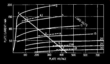
Fig. 205. Plate-voltage-current curves of the 6L6 showing load line
and operating conditions. +
The average plate current changes with application of the signal. It is important to see that the change of current is not ac companied by a change of de voltage supplied to the plate circuit.
For the comparatively small changes of current occurring in class-A power stages, a sufficiently large terminating capacitor in the power supply filter is sufficient to meet the case. In general, any thing less than 8 uf is not recommended for good-quality reproduction and can with advantage, be greater.
Slope of the load line
The slope of the load line represents the effective impedance reflected across the output transformer primary. This winding has resistance; call it R' ohms. The slope of the load line is not altered by this, but the actual working plate voltage is less than the supply voltage by the amount R'I0.The transformer primary also has reactance, as has the speaker itself. A reactive load converts the load line into an ellipse. This disadvantage can be overcome to a great extent by increasing the transformer primary inductance. Further information on this point will be given in the section dealing with output transformers.
A simple design trick, which the writer first met 28 years ago, is available for drawing a suitable load line to give 5% distortion.
For this amount of distortion, in Fig. 204 the ratio of XO to OY is as 11 to 9. If now, a straight piece of cardboard in the form of a ruler about 8 inches long is marked with a center zero and is also marked off in divisions to left and right of this center zero in the ratio of 11 to 9, the rule can be placed so that the center rests on the point of operating bias (in the case of the 2A3 at -45 volts) and pivoted about this point until the curves at minimum and maximum bias register on equally marked lines on the rule.
A line drawn along the edge of the rule will then give a load line representing a value for 5% distortion. For convenience, the di visions to the left of zero can be made 11 mm and to the right 9 mm. The divisions should be marked 1 to 10 to left and right and should also be subdivided by half-way shorter marks. Visual interpolation will take the place of smaller subdivisions.
Single tetrode output stages
Normal operating data for tetrodes in class A1 are given in Table 5. Graphical methods are similar to those for triodes but somewhat more complicated. Fig. 205 gives the plate-current plate-voltage curves for the 6L6 tube. The load line is shown by XOY as before but, as the power output and distortion vary widely with change of load, the tetrode being critical as to correct loading, a different technique must be used.
The load line in Fig. 205 represents a load of 2,500 ohms, as quoted in Table 5. The difference between XO and OY is quite appreciable. This is reflected in the table, which shows that the second-harmonic distortion is 10%. For optimum operation of a tetrode a method of trial and error must be adopted.
Determine the operating point 0, whose ordinates are the operating plate voltage and the maximum signal current. From a point just above the knee in the zero-bias curve draw a line through O and continue so that XO is equal to OY. By the standard data provided, 0 should be on the curve of the specified bias.
If on inspection it is found that the change of bias from X to O is not the same as that from O to Y, the load line is not suitable and another attempt must be made. For example, in Fig. 205, OX and OY are not equal. When the best approximation has been found, the following formula can be evaluated. Point X represents E_min and Imax; Y represents Emax and I_min•
Emax – E_min Load resistance [Rd = ----- Imax – I_min
Power output and harmonic distortion
Calculation of the power output and harmonic distortion is a little more complicated. The simplest technique is that usually called the "five selected ordinates method." We have already three ordinates-X, 0 and Y, the other two are at X1 and Y1. These points are the intersections of the load line with the bias curves representing bias of values:
where V is the normal bias at point 0. Then:
Power output
[ (Imax - Imin) + /2 (Ix - I1)] 2 RL 32 I_max + I_min - 210
% 2nd harmonic distortion = _ /2. [I _ 1] X 100 lmax lmln + x y
. . . Imax - Imin - /2. Ux - I,]
% 3rd harmonic d1storuon = m [ ] X 100 max - Imin + ..; 2 Ix - I,
% total 2nd and 3rd harmonic distortion= ? [% 2nd]2+[% 3rd]2 where 10 , Ix and 11
are the plate currents at points 0, X1 and Y1 in Fig. 204.
A complete picture of the behavior of the tube can therefore be plotted by evaluating these equations for different load lines.
Such curves are given in the RCA tube handbook and need not be repeated here. The third harmonic is liable to be more objectionable than second and low loading of a beam-power tetrode gives less third harmonic distortion than high loading; it also gives less power output. Accordingly, a nice balance must be made between the power output desired and the amount of harmonic distortion permissible. As these tubes give much less third-harmonic distortion than second with low loading, it is clearly advisable to use them in push-pull, which cancels even-harmonic distortion.
Push-pull triode output stages
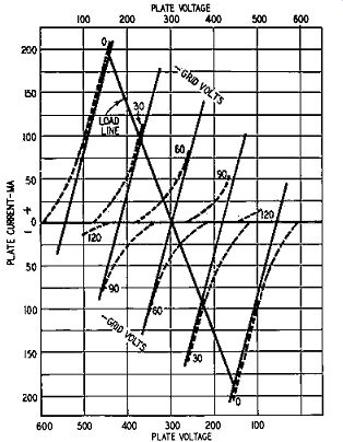
Fig. 206. Combined characteristics of two ZAJ tubes in push-pull.
Fig. 206 shows the plate-current-plate-voltage curves for two 2A3's in push-pull. The upper half of the diagram is identical with Fig. 204 except that intermediate values of bias have been omitted for the sake of clarity. The lower half of the diagram is precisely similar except that it has been turned through 180° and the plate-voltage axes are made to coincide with the operating points, in this case 300 volts, superimposed. The grid-voltage curves are shown in Fig. 206 as dashed lines. From these, de rived characteristics (shown as solid lines) are obtained by averaging the plate-current-grid-potential curves corresponding to the same applied signal. The "curves" shown in the figure are straight lines, and for class-A amplification they will be nearly straight. As one passes to class AB1 , and eventually to AB2, they will depart more and more from the straight line, but this divergence does not invalidate the basic argument.
For the operating bias, -60 volts, the derived curve represents no signal on the grids, so the two -60-volt curves are averaged. If the signal on the first grid is 30 volts, the net bias is -30 volts; but the signal on the second grid is -30 volts, so the bias on the second grid is -90 volts. Accordingly, the curves for -30 and -90 volts are averaged. And so on. The derived characteristics represent the relationship between the plate-to-cathode voltage (half the plate-to-plate voltage) and the difference between the two plate currents (twice the alternating current in a plate-to-plate load resistance). Accordingly, the load line shows output voltages and currents when the output transformer has a stepdown ratio of 2.
Matching tubes
Push-pull tubes, for optimum results, should be matched. Maximum power output is obtained when the plate-to-plate load resistance is four times the plate resistance of the composite tube, the composite tube being that whose characteristics are the composite ones shown in the figure, or roughly twice the plate resistance of one of the tubes at the quiescent operating point. Any load resistance less than this will cause a loss of output power, in crease distortion, create high peak currents and excessive plate dissipation. The actual value of plate-to-plate resistance in ohms for any load through the point where it intersects the plate-volts axis at the operating voltage is found by projecting the load line to intersect the plate-current axis. Call this point of intersection I amperes and the operating point on the plate-volts axis E volts.
Then the plate-to-plate load resistance is 4E/1.
The power output = Umaxl2 X RL/8 where RL is the plate-to-plate load resistance. I is, of course, the current at the point where the load line cuts the zero grid-bias curve. Since a perfectly balanced push-pull output stage has no even-harmonic distortion, no calculations of these arise; but the third harmonic can be evaluated by the formula already given, with the notation that the quantity 10 is now zero, and that "minimum" currents are now negative.
Push-pull tetrode output stages
The same method applies here and composite characteristics can be drawn in a manner similar to that for triodes. Actually, for calculation of the power output of tubes of the 6L6 type, where third-harmonic distortion is small, composite characteristics need not be drawn. In Fig. 204, if the load line is drawn from the zero grid-volts curve through the operating voltage at zero cur rent, the power output = ½ Imax [Emax – Emin]. As with single tubes it is essential that the screen voltage be held constant within narrow limits for maximum power with minimum distortion; with class ABi, the plate voltage should also be well regulated. In all cases the correct load resistance is much more important than with triodes.
Class B and class AB2 output stages
These are used for maximum economy of design when large outputs are required. Obviously the plate dissipation of a tube (ac+dc) cannot be exceeded without shortening its life. If the quiescent current is reduced (by increasing grid bias) the dc dissipation is reduced and dissipation for ac power increased. In class-B amplifiers the bias is increased to the cutoff point; one tube handles one-half cycle of the signal, the other deals with the other half cycle. A reasonably close approximation for power output and load resistance can be obtained by assuming that the characteristic curves are parallel straight lines when:
EP- E_min Load resistance, plate-to-plate = 4 --- Imax
Power output from two tubes where Ep is the plate supply voltage; E_min the minimum plate voltage during one cycle, and Imax the peak plate current.
The bias must remain constant over wide variations of plate current and so must be provided from a battery or separate power supply.
Class-AB2 amplifiers are intermediate between class B and class AB1. The plate current variation is less than with class B (about half as much) and the amplifier is a compromise between the high plate efficiency of class Band the low distortion of class AB1 . Again, fixed bias is essential.
Table 4-Output triodes in class A1
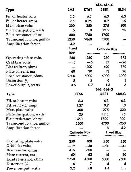
The tubes in this table are triodes or triode connected tetrodes.
Where the listed tube is a tetrode the information given is for maximum, and typical operating conditions when the plate and screen grid of the tube are tied together.
Table 5-Output Tetrodes in Class A1

This table includes tubes commonly used in low-cost low-power audio amplifiers such as may be found in the output stages of radio and television receivers and inexpensive phonographs.
Table 6-Output triodes. Push-pull operating conditions

Table 7-Output tetrodes. Push-pull operating conditions
Tetrode tubes in this table are triode connected. Values are for two tubes.
For the KT88 separate bias resistors of 560 ohms are essential.
a: common screen resistor of 1,000 ohms.
b: common screen resistor of 470 ohms.
c: individual series screen resistors of 1,000 ohms from 43% tapping of the output transformer.
Distortion in the KT88 depends on accuracy of matching.