THE two tubes in a push-pull power output stage require input signal voltages of equal magnitude but of opposite phase.
The signal voltages driving the push-pull stage must be symmetrical with respect to ground: this operation is carried out by a phase inverter. Normally the signal output of the last stage of the voltage amplifier (driving the push-pull tubes) is sufficient to develop maximum power in the output stage, in which case the phase inverter immediately precedes the output stage itself. ·where this is not the case (particularly where the output stage consists of two triodes in class AB2), the penultimate stage is itself push-pull and the phase inverter precedes this stage. Such a penultimate stage is called a driver.
Inductive phase splitters
The simplest method of phase inversion is to use an inductive device, such as a transformer or center-tapped choke. Fig. 301 shows various methods. In Fig. 301-a a transformer with center tapped secondary is connected in the conventional manner. This method is simple and inexpensive if high-quality reproduction is not essential, but a transformer for high-grade results is rather difficult to design and expensive to make since a wide frequency response with linearity is necessary.
For good bass reproduction the primary inductance must be adequate and since it carries de the design must be generous. For good treble response the self-capacitance of the windings must be low and with the generous design postulated for good bass the requirements are in conflict.
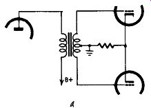
Fig. 301-a. Inductive phase inverter using center-tapped transformer.
These difficulties can be avoided by using a transformer with a high-permeability core, when the windings can be small and a good frequency response secured. Such a transformer must be parallel-fed, as shown in Fig. 301-b. The secondary winding need not be center tapped, for two equal resistors can be connected across the winding to give the center tap. Suitable values would be between 100,000 and 250,000 ohms. A resistive center tap could be applied to the transformer in Fig. 301-a.
Finally, a center-tapped choke can be used as shown in Fig. 301-c. This method is not very satisfactory owing to the loss of gain as compared with a transformer and the difficulty of getting perfect balance between the upper grid which is coupled directly (through the capacitor) and the lower one, which is coupled through the choke.
Stage gain
The stage gain of Fig. 301-a is the same as though phase inversion were not used and a usual ratio for the transformer would be a stepup of 1 to 2. In Fig. 301-b, where T is the transformation ratio and R the sum of the two resistors across the secondary winding, the load reflected into the previous tube is R/T2. As the optimum load on the preceding tube is the determining factor for output and distortion, the resistors must be selected to achieve the desired load. In all three methods the output tubes can have common bias or separate bias, as shown in Figs. 301-b and 301-c. A common-bias resistor bypass capacitor is not normally required or desirable. With separate bias, adequate capacitive bypass is necessary to avoid loss of bass.
Vacuum-tube phase splitters
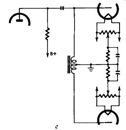
Fig. 301-c. Inductive phase inverter using a center-tapped choke.
Inductive phase splitters can be avoided by using a vacuum tube for the purpose. In Fig. 302-a the signal is applied to the grid of V1, amplified in the normal manner and passed on to output tube V3.
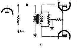
Fig. 301-b. Inductive
phase inverter using a resistive center-tapped transformer.
A tap on the grid resistor of V3 is selected so that the signal 6 voltage fed to the phase-inverter tube V2 is identical with that fed to V1. If V1 and V2 are matched tubes and their associated R-C networks are identical, V3 and V4 will receive signals equal in magnitude but opposite in phase. It might be said that V2 takes the place of the transformer of Fig. 301-a. Tubes V1 and V2 can, of course, be twin triodes in one envelope, as can similar pairs in other circuits given.
The phase inverter tube V2 can be eliminated by using the arrangement of Fig. 302-b where the upper output tube is also used as a phase inverter; its half of the output transformer is shunted by a tapped resistor from the tap of which out-of-phase voltages are fed to the grid of the other output tube. This circuit has the ...
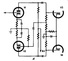
Fig. 302-a. Vacuum-tube phase inverter with excitation from the grid
of the output tube.
... merit of cheapness but it is not recommended when negative feed back is used as complexities of phase shift can occur to cause instability.
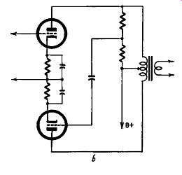
Fig. 302-b. Vacuum-tube phase inverter with excitation from plate of
the output tube.
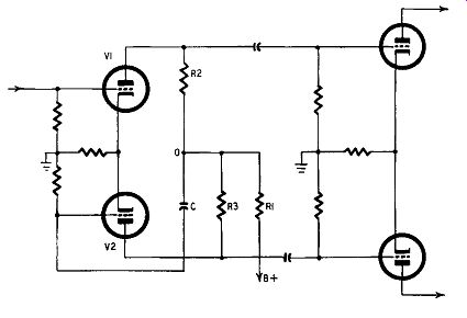
Fig. 303. Self-balancing phase inverter (floating paraphase).
These two circuits are not self-balancing and require adjustment for balance when first set up with every tube replacement.
Also, because the circuits associated with V2 have two coupling capacitors as compared with one in the plate circuit of V1, they will be out of balance with the circuit of V1. They are unsuitable for class-AB2 output stages as the grid-cathode resistance presented to the push-pull tubes is too high.
A driver stage may be needed for these types and the inter-tube coupling should be a transformer with center-tapped primary and secondary windings or a direct-coupled pair of cathode followers.
Self-balancing inverter
A self-balancing phase inverter is shown in Fig. 303. Resistors RI and R2 are the ac load on tube V1; R1 and R3 the load on V2. R1 is obviously common to both. Unbalance in the plate currents of the two tubes generates a voltage across R1 which is applied to the control grid of V2 through capacitor C. The potential of point O is floating, changing as the plate currents of the two tubes vary with respect to each other; this gives the circuit its name of "floating paraphase." Schmitt inverter Fig. 304 shows a different type of self-balancing phase inverter (credited to Schmitt). It is cathode-coupled and exact balance can be obtained by suitable adjustment of the two load resistors.
The component values given in the figure have been found to be most suitable and it should be noted that the coupling capacitors in the two grid circuits should have very good insulation resistance.
Tube type 6C8-G should be used.
Split-load phase inverter
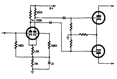
Fig. 304. Self-balancing phase inverter (Schmitt).
One of the simplest and most widely used phase splitters appears in Fig. 305. Usually the load on a tube is in the plate circuit; with a cathode follower the load is in the cathode circuit.
The circuit of Fig. 305 shows the load divided between plate and cathode circuits, but also included is an unbypassed cathode-bias resistor R2. Now, degeneration (negative feedback) is set up if the bypass capacitor across the bias resistor is omitted, but this only operates at low frequencies when the electrode-ground capacitances are small in terms of. the signal frequencies. At high frequencies these capacitances act as partial bypasses so degeneration is not constant throughout the range of frequencies, with the result that the stage gain is not constant.
Phase splitting occurs when the output from the plate circuit equals that from the cathode circuit: R1 must equal R2 + R3.
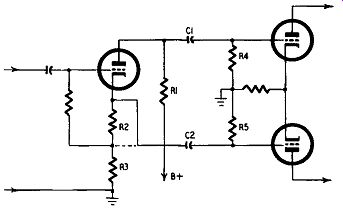
Fig. 305. Split-load phase inverter.
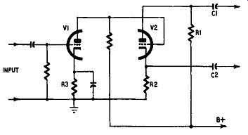
Fig. 306. Split-load phase inverter with preceding direct-coupled amplifier
to give full stage gain.
This does not mean that the resistors must be of very close tolerance for what is required is not accuracy of individual resistors but equality of plate and cathode loads. Similar care in balancing the circuit constants must also be exercised in the case of coupling capacitors C1 and C2 and the grid-circuit resistors R4 and R5 of the following stage. This precaution is necessary not only to secure perfect phase splitting; unbalance can cause instability of the type known as motorboating.
Normally the cathode output is taken directly from the cathode as indicated in Fig. 305 but, particularly with tubes of low amplification factor, it may be better to take the output from the junction of R2 and R3 as shown by the broken line. Exact mathematical analysis of the alternative connections could be given and prove nothing for in practice the choice can be made only by ob serving the output of the amplifier on an oscilloscope for a given signal input. Changing the connection to C2 from the cathode of the phase splitter to the junction of R2 and R3 will then show, for maximum undistorted output, which is better. The writer has found that for tubes such as the 6J5 the best results are obtained when the output is taken from the junction. In either case the stage gain of the phase inverter is somewhat less than I, usually about 0.8 to 0.9.
Split load inverter with direct-coupled amplifier
This disadvantage of less than unity stage gain can be overcome by a trick which if it involves the use of another tube does not at least involve fitting an extra tube holder in the amplifier chassis. Consider the circuit of Fig. 306 with respect to that of Fig. 305. Tubes V1 and V2 are the two sections of a double triode, the section V2 representing the inverter tube of Fig. 305.
Section V1 is a straight voltage amplifier with a cathode-bias resistor equal to that of R3 in Fig. 305 and a load resistor correct for the tube as an amplifier. This tube is direct-coupled to V2, the phase-inverter tube, and the load of V2 is, as before, made up of R1 and R2.
This device improves the performance of the inverter quite appreciably for the advantages of direct coupling are secured in a greater gain without the use of extra grid-plate coupling capacitors, a matter of importance in reducing phase shift in a feed back amplifier; capacitors C1 and C2 can also be increased to as much as 0.5 ,,_f, a somewhat dangerously high value for the circuit of Fig. 305. It will be appreciated that the high value of cathode resistor makes the split-load inverter particularly suit able for direct coupling. The voltage drop across the cathode resistor is substantial compared with an ordinary amplifier and the cathode is at a comparatively high potential with respect to ground. Tube V2 is therefore in a "natural" condition for having its grid directly coupled to the plate of the preceding tube.
A word of warning is, however, necessary. The correct operation of inverter V2 is dependent on the correct de potential on its grid. This can only be controlled by the potential, on the plate of V1, and in practice it will be found that plate-load and cathode bias resistors should be somewhat larger than would normally be used for that tube. As with all phase-inverter circuits it is almost essential that symmetrical working be checked by oscilloscope tests.
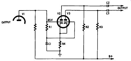
Fig. 307. Cathode-coupled or "long-tailed" phase inverter
showing direct coupling to preceding stage.
Cathode-coupled phase inverter In the paraphase circuit of Fig. 303 resistor R1 is common to both tubes of the inverter. Unbalance in the two plate circuit currents generates a voltage across it which is used to balance the whole circuit. This common load can be used in the cathode circuits of the tubes, creating what is known as the cathode coupled or long-tail inverter. This is illustrated in Fig. 307. It will be clear that there is a similarity to the split-load inverter because the potential of the cathodes is high with respect to ground. At the same time differences in the plate currents of V2 and V3 set up a voltage across R4, which is applied to the grid of V2 through capacitor C1. A suitable grid voltage for V2 is of the order of 85 volts, bearing in mind the comparatively high positive potential of the cathodes, and thus suggests that, as in the case of the direct-coupled split-load inverter, the input is direct-coupled to the preceding stage V1, and is so shown in Fig. 307. This inverter has good frequency characteristics but only half the gain of the circuit of Fig. 306. It is a popular circuit in Europe-the well-known Mullard 20-watt amplifier using it--and more recently has come into favor in the United States, where examples are to be found in the Eico 50- and 60-watt amplifiers, among others.
There is some difference of opinion as to the optimum values of associated components, which in any event depend on the type of double triode used for V2-V3. The following data compares Mullard with Eico practice.
Tube: R1 R2 R3 R4 C1 C2 C3
Mullard: ECC83
1 Meg 180K, 180K, 82K 0.25 0.5, 0.5
Eico: 6SN7-GTB 1 Meg 28,750 33K 18K 0.25, 0.25, 0.25
Drivers
The stage before the output stage is generally called the driver, although the term is more often restricted to the rather special driving conditions in class-AB2 and class-B amplifiers. In these, a considerably greater signal voltage is required than with class-A or AB1 output stages. As the tubes of a class-AB2 output stage are driven into grid current, a low resistance for the grid circuits is essential and an interstage transformer is generally used.
Transformer coupling
In transformer-coupled amplifiers it is customary to use general purpose triodes having a plate resistance of about 7,500 ohms, such as the familiar 6J5. The output voltage of such a tube can be obtained from its characteristic curves in a manner similar to that for output tubes. The higher the plate voltage the higher the output ac voltage before distortion commences. If one tube is insufficient to drive the output stage to full output, then two should be used in push-pull (the use of a large single power tube would call for a costly design of the interstage transformer). The transformer would then have both primary and secondary windings center tapped. This is actually an advantage since the opposing plate currents in the two halves of the primary winding call for a smaller core than with one tube, and in terms of frequency response, a better performance is obtained from the transformer.
Overall gain
The overall gain from a transformer-coupled triode is about equal to the product of the amplification factor of the tube and the stepup ratio of the transformer. The 6J5 has an amplification factor of 20, and with a plate voltage of 250 and a grid voltage of -8, the plate current is 9 ma. One tube would be quite ·unable to drive two triodes in class AB2 and even 9 ma plate current is rather high polarizing for an interstage transformer. In class AB2, moreover, the driver has to supply power and transformer losses can be appreciable. Two tubes are necessary and, being in push pull, they make the task of the transformer a simpler one to fulfill. Detailed design of class-B amplifiers is rather complicated and space here does not permit full treatment. The interested reader is referred to the standard textbooks on the subject. In brief: Class-AB2 amplifiers operate similarly to class AB1 and the driving voltage required is less than with class B. If a transformerless phase splitter is used, remember that in adequate care in design may introduce distortion and instability, mainly through out-of-balance components.
Parasitic oscillation can occur in the grid circuits of the output tubes which can largely be avoided by using a driver transformer having low leakage inductance.
Resistance-coupled driver stages are fairly widely used, particularly when the output stage is two push-pull triodes, or tetrodes or pentodes connected as triodes. This is necessary since the grid-to-grid swing required for maximum output from two triodes is considerably greater than that for tetrodes or pentodes.
Push-pull drivers
1-DETERMINE DESIRED OUTPUT POWER
2-SELECT TUBE CAPABLE Of' DELIVERING REQUIRED POWER
3-DETERMINE REQUIRED GRID VOLTS
4-SELECT DRIVER (INVERTER) TUBE THAT CAN PROVIDE REQUIRED DRIVE VOLTAGE DRIVER C INVERTER) STAGE
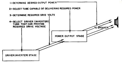
Fig. 308. Steps in the design of an audio power amplifier.
Sometimes a push-pull driver stage is used to swing a pair of tetrodes, apparently on the supposition that there will be less distortion than when using a single tube. This notion is carried to its logical conclusion in designs which show an amplifier entirely push-pull. In theory, perhaps, it could be shown that a wholly push-pull amplifier has less overall distortion than one in which the voltage amplifier is not push-pull, but in practice, if the voltage-amplifying stages are properly designed, the elaboration is unnecessary. It is also undeniable that the simpler an amplifier the less the possibility of distortion creeping in through tube or component deterioration.
Design sequence
Yet the penultimate or driver stage must have sufficient output ac voltage to swing the push-pull output stage and, if the phase inverter is unable to deliver that voltage without distortion, then the driver stage must be push-pull. A particular type of tube can deliver only so many output volts without distortion, whether it is used as a voltage amplifier or phase inverter. This fact is some times not appreciated, since technical writers are often asked for an opinion as to the best type of inverter without any mention being made of the output stage of the proposed amplifier. Hence the sequential treatment in this guide. The output stage must first be selected. Given this, the required input grid volts are known. A tube is then selected which will give that voltage output. If, choosing from among the tubes that are normally used as phase inverters, it is found that the desired voltage cannot be obtained, the driver stage must be push-pull. Then, and only then, can the type of phase inverter be selected. (See Fig. 308.) This is a problem in voltage-amplifier design, which will be discussed in the next section. The matter is mentioned at this stage simply because the driver is a voltage amplifier and properly belongs to the next section, but may come under the scope of the present section because it may be simply a phase inverter if the output stage does not require a large input grid voltage.
Suitable tubes for use as phase inverters are listed in Table 10 at the end of Section 4.