POWER is required to drive a speaker or a recording head. The power is obtained from the power-output stage, and to get this power, a voltage of the correct magnitude has to be impressed on the grid circuit of the output stage. As the actuating signal de vice (phono pickup, signal voltage across the detector diode load, etc.) has a voltage output considerably less than required, amplification of the signal voltage is necessary. The voltage amplifier performs this task. It cannot be a pure voltage amplifier since the load into which it works does not have infinite impedance, so there will be some power in the output. The output load may be as high as 1 megohm, but is frequently less, and in the case of transformer coupling may be unknown. The number of stages required in a voltage amplifier depends on the degree of amplification required, postulated by the input and desired output voltages and the type of tubes selected. The fewer the tubes, the less likelihood of instability through a common plate supply impedance, but a selection of tubes giving a high stage gain may result in undesirable performance. The design of the amplifier is wholly dependent on the degree of absence of distortion required.
Transformer-coupled stages have already been mentioned. Almost invariably resistance-capacitance-coupled tubes are used in voltage amplifiers, so further discussion on transformer-coupled stages will not be given. Either triodes or pentodes may be used and an examination of their characteristics can be carried out in a manner similar to those of output tubes.
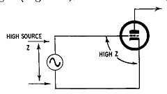
Fig. 401. Source and grid-to-cathode impedances are generally high.
Resistance-capacitance-coupled triodes
It is customary to use either general-purpose (medium-mu with an amplification factor under 50) or high-mu triodes (amplification factor 50 to 100). The tube manufacturers publish resistance capacitance design charts for all types of tubes, but a word of warning is needed in connection with these. The figures given seem to indicate that a low source impedance is used whereas in practice the source impedance and grid-cathode impedance are usually fairly high (Fig. 401); therefore, the values of associated components are not necessarily correct. These charts also refer to average tubes and so can be taken only as a rather rough guide in specific cases.
The figures given also assume a harmonic distortion content of 5% and for high-grade equipment this figure is excessive. In view of the fact that distortion occurs when the tube is called upon to deliver its peak voltage, the obvious way to avoid it is to work the tubes well within their limits. Accordingly, for high-grade amplifiers the designer should not expect to get the voltage output from any particular tube that the chart would indicate as being possible.
This does not mean that the overall gain of the amplifier must be determined so that no tube has to produce more than about three-quarters of the possible output voltage. As this limitation usually arises only in the last stage of the voltage amplifier, earlier stages, including so-called preamplifier stages, may be selected on the basis of the charts. If the last tube is unable to deliver the necessary voltage to drive the output stage or driver stage, then the last stage of the voltage amplifier would have to be a push-pull stage and the phase-splitter would be a part of the voltage amplifier.
Design data
For convenience in design the mass of data presented by the tube makers has been edited and put together in different form.
After eliminating some unnecessary information, what is left produces a recognizable pattern. Table 8, giving the correct values for average triodes of the types listed, is subject to the limitations mentioned. As most designers are interested in equipment deriving power from a line-operated supply, battery operating types of tubes have not been included but the relevant information can be extracted from tube-makers' manuals.
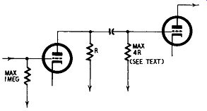
Fig. 402. Relative values of plate and grid resistors.
The input resistance should not exceed 1 megohm and subsequent grid resistors should be not more than four times the preceding plate resistor (Fig. 402). With high-mu triodes the grid resistor should be less than this. High values of grid resistor tend to produce hum. It should be remembered that output tubes require a lower grid resistor than an ordinary voltage amplifier (the recommended values being given in the tube handbooks) but a simple rule is to keep this as low as 250,000 ohms for high-grade equipment. With this in mind an examination of Table 8 shows that quite a number of alternative usages are ruled out on the grounds that the value of R3 will be too high. If R3 is 0.5 megohm, several opportunities occur of getting a higher output voltage from the preceding tube, but it should be remembered that the 0.22 megohm value is recommended to reduce the effects of reverse grid current in the output stage.
Coupling capacitors
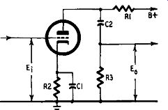
The value of the coupling capacitor C2 is important. If too small, there will be a loss of amplification at low frequencies. The values shown allow for the amplification at 50 hz to be reduced to 0.8 times the amplification at higher frequencies-a loss of 2 db. If this capacitor is reduced by one-half, the 2 db loss will be at 100 hz; if doubled, the 2 db figure is reached at 25 hz, and so on.
If the capacitor is too large and the whole amplifier has a tendency to motorboat, the motorboating frequency will be passed on without attenuation. So a simple way to stop motorboating is to reduce the value of the coupling capacitors. But this must not be done to such an extent that appreciable loss of amplification occurs at low frequencies; the cause of the instability must be sought out.
For inexpensive equipment, C2 can be half the values shown; for high-fidelity amplifiers it should be double. Any further increase will not contribute audibly to quality of reproduction but can permit the transfer of subsonic frequencies.
C1 is most conveniently (and least expensively) an electrolytic capacitor. One rated at 10 µf with a working voltage of 25 or 50 will be suitable for all cases.
The supply voltage should be as high as possible, with a maximum of about 300. Examination of the figures for output voltage show clearly that about double the voltage swing can be had by raising the supply voltage from 180 to 300, the gain not being appreciably affected. The greatest output voltage is obtained when the plate load R1 is highest but, as this requires a high following grid resistor, it may not be possible to use this condition with high-fidelity output stages.
A push-pull output stage requires double the input signal voltage needed to drive a single tube so, in ·selecting a suitable tube from Table 8, the required grid-to-grid voltage must be remembered. If a single tube will not supply this voltage (and for mini mum distortion the designer should expect to get only three-quarters of the output voltage Eo shown in the table) except by using a high plate load, then push-pull working must be used. In general an output stage of two triodes (or two tetrodes connected as triodes) in push-pull will require a push-pull driver stage; two tetrodes can be driven from a single tube.
Resistance-capacitance-coupled pentodes
Table 9 shows suitable operating conditions for resistance capacitance-coupled pentodes. In a general way considerations are similar to those for triodes, but an additional factor must be taken into consideration-high-frequency attenuation. As will be seen from the data given at the head of the table, the value of the plate load has a bearing on the width of frequency response of the amplifier and R1 must be selected with the performance required in mind.
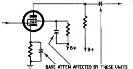
Fig. 403. Amplification of bass is affected by the size of the coupling,
cathode and screen bypass capacitors.
For a rather low plate load the stage gain is not appreciably greater than that obtainable from a high-mu triode and the question may be asked, why use pentodes at all? This involves consideration of the dynamic characteristics of both types and, contrary to generally held opinion, a pentode as a voltage amplifier can give a good deal less distortion than a triode.
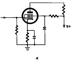
Fig. 404-a. Usual method of applying screen voltage.
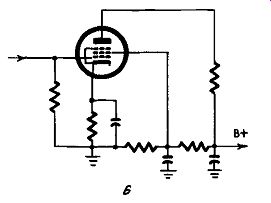
Fig. 404-b. Voltage divider for the screen is a better technique.
Examination of a tube such as the 6SJ7 used as a triode or as a pentode will show that, for outputs up to about 10 volts rms, the intermodulation distortion of the pentode is about one-eighth that of the triode, assuming that the operating conditions of both are optimum. At 30-volts output the distortion is about the same; at 60 volts output the pentode has more distortion than the triode. So a pentode is most useful in the earlier stages of an amplifier where the signal voltage to be handled is low. In these positions the pentode has a higher amplification factor and less distortion than the triode and is strongly recommended for high-fidelity amplifiers.
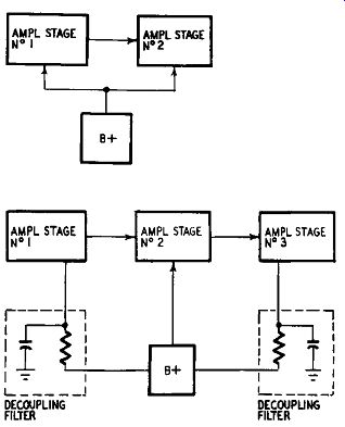
Fig. 405. Block diagram of decoupling circuits. When two or more amplifier
stages are used power supply decoupling is necessary.
Bass attenuation is affected by the screen bypass as well as the cathode bypass and coupling capacitors. If, instead of a series screen resistance as shown in Fig. 404-a (the usual method of feeding the screen) a potential divider is used as in Fig. 404-b, the loss of bass through inadequate bypassing is very much less. This has the further advantage of stabilizing the screen potential to some extent, a desirable aim with all pentodes.
The cathode bypass will be seen to be greater than that required for triodes, and it is most convenient to use an electrolytic capacitor of 50 uf with a working voltage of 12, or over.
Resistance-capacitance-coupled phase inverters
Table 10 summarizes in convenient form the conditions that have to be met when using twin triodes as amplifying phase inverters. No-gain splitters have already been dealt with in Section 3, but the table gives the values required for a circuit of the type shown in Fig. 302-a. For the twin triodes included in Table 10, the values shown in that table should be used for R1, R2, R3 and C but as the output from the two triode sections of the double triode must be equal, the tap on R3a and R3b must be adjusted to suit.
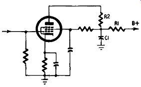
Fig. 406. R1 and C1 form a dc coupling network.
The twin triode is an amplifier hence the tap on the grid resistor of one output tube must be selected so that the voltage applied to the second triode of the phase inverter is such that the voltage across the grid resistor of the second output tube is identical. If the voltage gain of the stage is, say 20, then the input signal voltage E; would be one-twentieth of the output voltage, so the voltage tapped off R3 would be one-twentieth of the total voltage across the two.
Decoupling
In the discussion on triodes it was stated that the supply voltage should be as high as possible, with a maximum of 300, but this assumes that the supply voltage is applied directly to the load resistor. If an amplifier has only two stages, decoupling is probably unnecessary; but more than two stages are needed in all but the cheapest equipment. Decoupling then becomes essential to overcome common impedance coupling in the power supply. See Fig. 405.
Decoupling involves the use of a series plate resistance R1 with a low impedance bypass to ground, C1, between the supply source and the load resistance R2 of the tube as shown in Fig. 406. As the tube takes plate current, a very appreciable voltage drop takes place across the decoupling resistance. The higher the value of the decoupling resistance, the better the decoupling (assuming an adequate bypass to ground). For a supply voltage of 300 applied to the plate resistors, it can be taken as a safe working rule that the actual supply voltage should be 400, or a little more, and the bypass capacitor has a capacitance of 8 µf with a de working voltage of 500.
Table 8-Resistance-capacitance-coupled triodes
C1 and C2 adjusted to give 0.8 Eo at 50 hz.
Data for double triodes (types 6SN7-GTB, 12SN7-GT, 6SL7, and 12AX7) apply to each triode section.
R1 and R3 in megohms; R2 in ohms.
V.G. (voltage gain) = Eo/E1.

Table 9--Resistance-capacitance-coupled pentodes
C1, C2, C3 adjusted to give 0.7 E 0 at 50 hz.
Upper limits of level frequency response for values of R'l:
R1 = 0.1 megohm-25,000 hz.
R1 = 0.25 megohm-10,000 hz.
R1 = .5 megohm- 5,000 hz.
R1, R2, R4 in megohms. R3 in ohms.
V.G. (voltage or stage gain)
Eo/E1.
The 6SH7 and 12SH7 are particularly susceptible to hum when used as high gain audio amplifiers. When the tubes are used as low level drivers this un desirable characteristic need not be considered. However the tubes should be isolated from external hum sources whenever possible. Two separate cathode connections permit the input and output circuits to be isolated from each other.
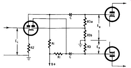
Table 10-Resistance-capacitance-coupled phase inverters
This table includes double triodes normally used as voltage amplifiers.
Other tubes can also be used; e.g. the double triodes listed in Table 8, where the operating conditions listed in that table should be used.
C is selected to give 0. 9 E0 at 50 hz.
R3a+R31 ,==R3. R3b is selected so that the voltage output of each triode of the double triode is equal; e.g. if V.G. = 20 then R3h/R3 = l /20. R1, R3 in megohms. R2 in ohms.
V.G. (voltage or stage gain) E 0 /Ei.