WITH the aid of Tables 4 to 10 it is now possible to work out the approximate design of a whole amplifier. As a working example, let it be supposed that a circuit is required for an amplifier to give 20 watts of audio power for a signal input of 1 volt, using a minimum number of tubes, yet avoiding excessive distortion. An examination of Table 6 shows that most triodes will not meet the power-output requirement, but Table 7 shows that two 6L6's as tetrodes in class-AB1 will.
From Table 7 it is seen that a peak grid-to-grid input of 57 volts is required to give a power of 24 watts. A phase splitter is required, and if the cathode resistor type of Fig. 304 is used, with a gain of less than unity, the input voltage to the phase splitter must be about 70 volts. Now examine Tables 8 and 9. The grid circuit resistance for 6L6's should be less than 0.5 megohm, so any line of data showing a higher resistance than this for R3 in Table 8 or R4 in Table 9 must be rejected.
Selecting a phase inverter
For 5% distortion in the intermediate amplifying stage the figures for E0 can be accepted, but this distortion is necessarily added to that of the output stage, so it is desirable to assume that E0 can be only 75% of the figures shown. The condition would seem to be met by a type 6BF6 operating at a plate supply voltage of 300 with a load resistor of 0.22 megohm. But the voltage gain is only 12 so a further amplifying stage would be required to meet the specification for input voltage. A high-mu triode could not be used here, because inspection will show that the required grid impedance for 6L6's cannot be met.
In Table 9 the answer would appear to be found in using a pentode, say a 6SF7, which, with a plate load of 0.22 megohm and a following grid resistor of 0.47 megohm will deliver 71 volts with a stage gain of 82. It would be a mistake to use a 6SJ7 which, with 0.1-megohm plate resistance will give an E0 of 96 volts with a stage gain of 98 because it is thought that the 71 volts from the 6SF7 should really be only 54 volts on the score of freedom from distortion. It has already been pointed out that a tube such as the 6SJ7 (or the 6SF7 for that matter) will give more distortion than a triode for 60 volts output. Moreover the stage gain of 98 is too high, for if an input of 1 volt is applied to the tube the output will be 98 volts, which is too high for the output stage. It might. be argued that the solution is to use a volume control in the grid circuit of the 6SJ7, but the amplifier should be designed to give maximum power with the volume control at maximum, otherwise part of the control is unusable. And a last point is that using a first stage with a no-gain phase splitter involves the use of two tube sockets and two separate tubes. Can this be reduced? Examination of Table 10 shows that it can. The grid-to-grid input of the output stage is 57 volts; that is, the input for each tube with respect to ground is 28.5 volts. Table 10 shows that the twin triode 6SC7 with a plate resistance of 0.1 megohm will give an E0 of 50 per triode with a stage gain of 34, the following grid resistance being 0.22 megohm. Since 75% of 50 is 37 volts, each triode is well able to deliver 28 volts to each output tube. As the stage gain is 34 and the required output voltage is 28.5, the input required for maximum power is thus 0.8 volt, a figure sufficiently close to the specification to be acceptable. Referring to the circuit diagram at the head of Table 10, the tap on R3 should be at 220,000/34 (= 6,470) ohms from ground.
Table 7 shows that the output stage needs a plate voltage of 360 for the required performance. But the cathode bias resistor applies a bias voltage to the grids of -22.5, so the total supply voltage required is 382.5. Allowing a margin for the potential drop in the output transformer primary winding the smoothed supply voltage should be 400. This is 100 volts greater than the voltage required for the twin triode and the excess voltage can be profitably disposed of by using decoupling resistors. These should be of a value to create a potential drop of 100 volts with the measured plate currents of the two triodes. The complete circuit diagram can now be drawn, and is shown in Fig. 501.
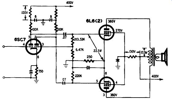
Fig. 501. Approximate amplifier design.
While this design is an approximation it is still a necessary first attempt at determining the correct tube sequence. Many other factors have to be taken into consideration: no individual tube will perform exactly as stated in the handbooks nor will the values of resistors and capacitors be what they are stated to be unless close-tolerance components are selected. This does not mean that tube and component manufacturers are in any way dishonest.
Close-tolerance tubes are not a "commercial proposition" but close-tolerance resistors and capacitors are selected from bulk manufacture by the method of preferred values; as they are the outcome of several selective processes they are necessarily expensive. This introduces a new aspect of the design problem-cost of production for a given set of requirements. Furthermore, the design may lead to unusual values for the resistors and capacitors.
For commercial production, a compromise may be made with the use of stock components as near in value to the design as possible.
Checking performance
The approximate design technique just described is based on the assumption that the tubes and components are what they are said to be. The data in Tables 8 and 10 has been derived mathematically, based on the use of preferred values of components of close tolerance, and "average" tubes, that is, tubes built to a pre-determined specification. When the circuit has been built up into a prototype amplifier the most satisfactory way of proving it is to measure its performance. Fig. 502. Method for determining the value of resistance required to obtain the desired screen grid voltage.
First check the applied de voltages with a very high resistance meter. The B+ voltage is to be checked for 400 volts approximately, but the actual voltage on the output plates with respect to ground should be 360. Table 7 shows that the screen voltage should be only 270. A series-feed resistance could be used or a potentiometer connected between B+ and ground, the tapping being taken to the screens of the tubes. Knowing the screen current, the tapping point can be calculated but the exact point can more easily be determined by connecting the voltmeter to the screens and altering the potentiometer until the desired voltage is obtained. If a fairly large bleed current is allowed to pass through the potentiometer (by making the total resistance not too high) better regulation of the screen voltage will be obtained, since the screen current variations will be a rather small fraction of the total current passing through the potentiometer. See Fig. 502. This screen feed is not shown in Fig. 501, but is easily understood.
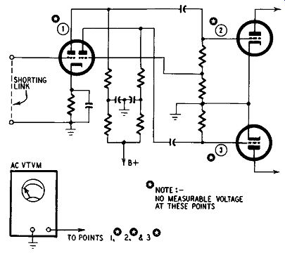
Fig. 503. Checking the preliminary design.
Next, the voltage on the supply end of the plate resistors of the double triode should be set to 300 by selection of suitable de coupling resistors. Using a vacuum-tube voltmeter adjusted to read ac volts, check that with the input of the first tube short circuited there is no signal voltage reading at the plate of the first tube, at the grids of the output tubes, or at the plates of the output tubes. If the meter shows a reading, then hum or some other disturbance is actuating the amplifier; this must be traced and eliminated. In the absence of a reading, the input circuit can be opened and an audio oscillator used to inject a signal into the amplifier. It was calculated that an input of 0.8 volt was needed for maximum output power, so set the oscillator for an output of 0.8 volt at a frequency of 1,000 hz. The output must be sinusoidal.
Checking stage gain
Applying the vtvm to the plate of the triode directly connected to the input will show if the tube is giving the correct stage gain for the output voltage divided by the input voltage should equal 34. But the reading obtained cannot be accepted without checking the waveform. Harmonic distortion may be present which will give an incorrect reading; (the instrument is calibrated on a sine wave). Freedom from distortion will be shown by shunting the vtvm with an oscilloscope. If the trace is a pure sine wave, no distortion is present and the voltage reading is reliable. The second triode must now be checked and it is of little consequence if the amplification factors of the two triodes are slightly unequal; what is necessary is that the voltages applied to the two output tubes be equal. The vtvm is therefore transferred to the second plate (and also the scope) and, if the output voltage is not identical with that from the first triode section, then the 6,470-ohm resistor must be altered until it is. This voltage will also be 180° out of phase with respect to the other because the capacitor values have negligible reactance at 1,000 cycles, compared to the resistance values. See Fig. 503.
In the absence of capacitive reactances it would be, for each amplifying tube causes a 180° phase change; the signal from the first triode plate is what might be called the direct signal voltage, but as a part of this voltage is applied to the grid of the second triode section, the output from the plate will be 180° out of phase with respect to the grid input. But the voltage applied to the second grid has passed through C1 which itself causes a phase change, so the output of the second triode is not exactly 180° out of phase with that of the first. If C2 were not present, the phase change caused by C3 would put matters right, but C2 is necessary otherwise the grid-cathode resistance for the second triode would be reduced to 6,470 ohms. Rg for both triodes must be equal to ensure equal amplification, and should have a value of about 0.5 megohm. Whatever value is selected for C2, phase balance must be obtained by adjusting the value of C3. This is most easily checked by connecting the oscilloscope across the output grid circuits.
The output stage can now be checked for waveform and power generated. This is most simply done by using a purely resistive load. Table 7 specifies a plate-to-plate load of 9,000 ohms, which is formed by using two 4,500-ohm noninductive resistors in series, with the junction point taken to B+. Therms current through the load is then measured. The power output in watts = 12R, where, in this case R is 9,000 ohms, 1 being in amperes. See Fig. 504.
The results of the work described here are not in themselves of very much practical value for the amplifier as it stands is not of very much use. The output load is purely resistive whereas in practice the load is resistive, inductive and capacitive and varies with frequency. An input sensitivity o" 0.8 volt is useless with a microphone, tape-recording head or high-fidelity pickup. No provision whatever has been made for a tone or even a volume control. Why then should space be apparently wasted in describing something of no practical worth? The answer is that too frequently designers and circuit hounds produce the whole outfit complete with gimmicks as a first step and then try to find out why it doesn't work. This can turn out to be an almost impossible task since so many things can go wrong.
By making the basic circuit work correctly first, then checking each supplementary circuit as it is added, the trouble can usually be quickly found because the complete hookup has been designed, made and checked stage by stage.
Component tolerance
It is at this point, too, that another factor must be reckoned with. It was stipulated that the components should be close tolerance, otherwise the predicted results cannot be expected. But close-tolerance components are expensive. It is useless to pick components at random out of a wide-tolerance stock for the sum total of errors may be so great as to make the circuit unworkable.
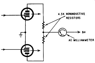
Fig. 504. A method for determining the power output of the preliminary
design.
Accordingly, by the degree of tolerance permitted in component selection, a margin of performance must be permitted in the circuit design.
The figures given for voltage output, power output and stage gain depend on the values of components being correct. If they are not, the performance of the amplifier will suffer at maximum but probably not at small outputs. In other words, maximum efficiency can be secured only by insistence on exact-value components and, as this is uneconomical, the design must be changed for one of lower overall efficiency. Tubes must be given less work to do so more tubes may be required.
Use of additional stages
There is certainly nothing deplorable in the use of an extra tube-it just happens that it is cheaper to use an extra tube than close-tolerance components. The designer, therefore, uses his discretion to produce the desired results at the lowest total cost. This being so, the tests already described should be repeated with components at the limit of the tolerances selected. If the factory is going to use 20% resistors and capacitors, then the circuit must be tested with components plus or minus this percentage, some being plus and some minus. It may then be found that for tubes selected at random the specified performance cannot be met with out adding a stage. If so the extra stage must be added. It may be that the desired output power cannot be obtained from the two output tubes under any circumstances, in which case it might be as well to refrain from calling the amplifier a "25-watt high fidelity" job and say what it is-possibly a very good amplifier with an "undistorted" output of 15 watts.
Having redesigned the basic circuit on these lines so that an honest performance is obtained with a sine-wave input of 1,000 hz, some other information can now be obtained. The original test was conducted at 1,000 cycles with a resistive output load because that is a set of conditions frequently used to make claims in advertisements of amplifiers. It may produce a good-looking set of figures but it is not the whole story. A high-grade amplifier has to reproduce all frequencies between about 20 and 20,000 cycles with constant output and constant small distortion. So the measurements must be repeated (with components on their outside limits) at spot frequencies of, say, 20, 50, 100, 1,000, 5,000, 10,000 and 20,000 cycles. If the amplifier is not intended to have a wider range than 100 to 10,000 cycles, then measurements outside these limits are unnecessary, but the designer should know what the amplifier is doing outside the specified limits to have some idea of what margin of safety his design possesses.
A circuit such as the cathode-resistance phase splitter of Fig. 305 cannot possibly work with 20%-tolerance components, although such components can easily be used in production. The success of the circuit depends on R1 being equal to R2 + R3 and C1 being equal to C2. Their exact values do not matter in the least-it is necessary only that the plate load be equally divided.
Accordingly, in production all that is needed is to select these components in matched pairs.
Using negative feedback
Finally, there is the question of negative feedback, which cuts right across all matters so far considered. Again, for a very good reason, this does not render the work done so far fruitless. Too frequently negative feedback is used as a cure for trouble rather than a technique for improving something. ·while negative feed back will sometimes counteract many bad features in an amplifier, in cases even a great deal of feedback will produce little improvement, or may even make matters worse. An equivalent amplifier can be made which will have a better performance without feedback than the defective amplifier with feedback. A competent and conscientious designer should be able to make a very good amplifier without availing himself of the benefits of negative feedback but, when it is applied to an amplifier that is already good, the final results are far in advance of the best designs without feed back. But the design must be right before feedback is applied.
Full development of the design for a high-grade 20-watt amplifier A few pages back it was said that the work so far done was not of much practical value and that the amplifier so designed would not be of very much use. The reasons for doing what was described lay in stressing the importance of getting back to fundamentals before embarking on a complex circuit. The complete design of a working high-fidelity amplifier may now be under taken, although the reader is advised to become acquainted with Sections 6 to 9 before proceeding. Perhaps this section might have been postponed until after Section 9 but as the discussion is centered on amplifier design and, as amplifier design is virtually adopting the correct sequence of tubes and the optimum method of coupling them, it is natural to follow on from the consideration of power and voltage-amplifying tubes.
Choosing the output stage
First, then, is the question-what is the best output stage for a high-fidelity amplifier for home use? There is no categorical answer to that question since personal tastes differ and rooms range from the small to the very large. Moreover some speakers are rather insensitive and others produce far more output for less input. But a general idea can be formed from much experience in audio work. It will probably be agreed that among discriminating listeners who aren't deaf and don't want to be deafened and who don't want to interfere with their neighbors' comfort, 20 watts provides a reserve of power for entirely satisfying results with a well-designed speaker in a fairly large living room. This postulates that the peak undistorted power is 20 watts; the mean output will probably be no more than l watt. And it is this very great difference between mean and peak powers in musical reproduction that causes so much heartache when the genuine music lover hears sounds from his equipment that he knows quite well are not music but distortion. But where does the trouble lie?
Tube characteristics
When dealing with tube characteristics, it was pointed out that the data is average data, typical only of the particular tube being considered. Moreover, these tube characteristics are taken with a sine-wave input; necessarily so, since a static state must be established for the measurements to be recorded. The figures quoted by the tube makers are quite accurate for an average tube and if the tubes are checked by the designer, with sinusoidal input, no discrepancy will be discovered. But whereas the output power is given for a resistive load, and speakers are resistive, inductive and capacitive, so also the output power is given for a sinusoidal input of constant peak value, and in speech and in musical reproduction the peak value is continually changing.
Push-pull output stages can be operated with fixed or cathode bias. Fixed bias is almost always essential with class AB2 and class B since the tubes are driven into grid current condition.
For the more ordinary class-AB amplifiers for domestic use cathode bias is customary since it is considered (quite correctly as it happens) that cathode bias is self-regulating. As the plate cur rent increases the voltage drop across the cathode-bias resistor increases, which results in increased bias voltage and reduction of plate current. See Figs. 505-a,-b,-c.
But things are not always what they seem. If the input is sinusoidal and then slowly increased from a low figure, it will be found that the self-balancing action does take place. If the same series of measurements is taken with fixed bias, it will be found that what was right for small inputs is not right for large inputs and distortion occurs. A class-B amplifier is usually in tended for economical production of high audio powers, such as are needed for public-address work, where the highest possible quality is not essential, reasonable intelligibility at the lowest cost being what is required. High-fidelity reproduction at more normal output powers is associated with cathode-biased output stages.
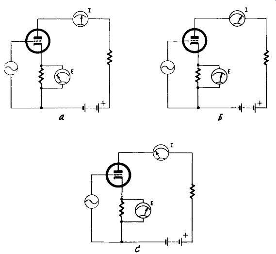
Fig. 505. Self regulating action produced by cathode bias: a) with constant
sinusoidal input, bias voltage and plate current remain at a relatively
steady level; b) as amplitude of input signal rises, plate current increases
and the bias becomes more negative; c) the change in bias tends to reduce
the plate current and the tube tries to return to its original operating
point.
If each output tube is biased separately, the bias resistor must be shunted by a suitable capacitance to avoid loss of bass. If the two tubes have a common bias resistor this is not necessary; indeed it is essential to omit the capacitor. The resistor and capacitor form a network which has a time constant; for good bass reproduction the impedance at low frequencies must be low to avoid attenuation (at high frequencies the impedance is negligible) and this implies a long time constant. When the section on negative feedback is studied, it will be found that a long time constant is needed in the interstage couplings to reduce phase change at low frequencies. This helps to create instability in the form of motorboating. Since the large capacitors have a low impedance for low frequencies, the long time constant of the bias network has an equally serious drawback when the input to the output stage is far from constant and also includes transient peaks of maximum amplitude. Music is neither loud nor soft all the time; generally it varies very considerably from something just above audibility to deafening crashes, with a mean output from a 20-watt amplifier of something of the order of I watt or a little less. So long as the mean input is such as to produce 1-watt output, the output will be undistorted and it will be obvious that the plate (and screen) current will be constant and the bias constant, too-in fact, fixed bias. But if the output tubes are used in class AB then an increase of input will produce an increase in plate and screen currents. This will be compensated by the increase of bias resulting from the increase of current through the bias resistor so long as the change is gradual. If a sudden increase of input is applied, shorter than the time constant of the bias network, there will not be time for the bias to change and the condition of fixed bias will continue in the peak, with consequent distortion. Hence the desirability of using a common bias resistor and no bypass capacitor because the time constant will be much shorter than when separate bias resistors are used, for these must be bypassed to avoid bass attenuation--See Figs. 506-a,-b.
Triode vs. tetrode output
A realization of this quite serious snag led to purists insisting that triodes in class A were the only tubes to use for the· best possible results. In class A the plate current does not change with variation in input so the problem does not arise. Yet the poor efficiency of triodes and the limited power available from class A amplifiers are· drawbacks just as serious. Hence the wide use of tetrodes in class AB, but a keen pair of ears can always hear the cleanness in the peaks of a triode class-A amplifier and the distortion in those from a tetrode class-AB amplifier-unless certain remedial measures are taken.
The first has already been given--a common bias resistor with out bypass. But it must be pointed out that a smoothing capacitor is shunted across the power supply and is consequently shunted across the bias resistor too. It is literally true that a substantial reduction in the capacitance of the power supply filter will help by reducing the time constant of the bias network, but such a reduction will impair the voltage-regulating properties when a large capacitor is used and make matters worse at all levels. Tetrodes and pentodes with constantly changing plate and screen currents demand good voltage regulation from the power pack. It will be found in practice that distortion will be reduced on peaks if the power supply filter capacitor is increased to something of the order of 50 uf. But the best way of all is to regulate the voltage by ancillary means such as the method given in Fig. 908 in Section 9. This permits a smaller value of capacitor in the power supply.
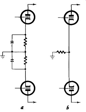
Fig. 506. Bypassing and cathode bias: a) when separate bias resistors
are used bypassing can be used to an advantage; b) when a common bias
resistor is used the bypass capacitor should be omitted.
Next comes the use of negative feedback and, as Section 7 makes clear, this must be used with discretion. Negative feedback can be used to such an extent that the distortion will be reduced to nothing; unfortunately the gain of the amplifier will also be reduced to nothing. Striking a happy mean between adequate gain and adequate absence of distortion, a point is reached at which, to avoid excessive phase change-which would change negative into positive feedback at low frequencies--the number of amplifying stages must be reduced to the minimum possible number.
Or, if several stages are desired, the feedback must not be taken over them all. A lengthy practical experience in amplifier design will convince the technical worker who has no preconceived bees in his bonnet that certain simple rules should be observed;
1. To secure the advantages of negative feedback, the minimum number of amplifying stages should be used. This postulates-
2. The output stage should be tetrodes or pentodes for the sake of their greater efficiency (resulting in a smaller required input voltage), provided steps are taken to reduce their effective plate resistance to give a good damping factor to the speaker.
3. The use of pentode voltage amplifiers both for their greater freedom from distortion and their greater voltage amplification per stage.
4. That high values of negative feedback should not be used to counteract amplifier shortcomings since this would reduce the overall gain too much and perhaps require an extra stage with the inevitable complications and instability.
Ultra-Linear operation
For something like 15 years the writer marketed a 20-watt amplifier consisting of a pentode voltage amplifier, a no-gain phase inverter and a pair of push-pull tetrodes. It gave this output power with only 0.7-volt input (an easy output for any tone control amplifier) and is still considered to have a very clean sound on the transient peaks. This is primarily due to a stabilized power supply and careful design. But it could be improved still more by comparatively recent developments variously called Ultra-Linear or distributed-load operation. With proper design, two tetrode-pentode tubes of 25-watt plate dissipation under Ultra-Linear operation will give 20 watts output power with appreciably less than 1% total distortion under actual working conditions, and 30 watts with only 1 % total distortion. This quality standard is good enough to satisfy the most critical listener and will be adopted for the present discussion. It has been found that the Mullard EL34/6CA 7 tube is particularly suitable for the type of operation now suggested, but other new tube types are becoming available which, no doubt, will give equally good results.
Positioning the transformer screen-grid taps The most noticeable departure from standard circuitry when using Ultra-Linear operation is that the screen grids of the out put tubes are taken to taps on the output transformer primary the load is "distributed." The reason for this must be understood so that the design of the circuit can be made with intelligence.
There is nothing mysterious in the operation if it is realized that an Ultra-Linear amplifier is a special type of feedback amplifier.
Negative feedback is used to reduce distortion and plate resistance, making the pentodes behave like triodes. But the power efficiency of the multi-electrode tube is retained, particularly from the point of view of required input grid volts. It is generally recognized by expert designers that greater stability and overall freedom from distortion are more readily obtained if the negative feedback is not just slung back in one large chunk from the output transformer secondary to amplifier input. It is usually best to counteract output stage distortion by a separate feedback loop.
This can be done by the simple circuit of Fig. 704-b in Section 7, and this was the usual method of applying feedback when the idea first broke into then-current circuitry thinking. Feedback over several stages was a much later development.
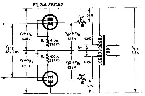
Fig. 507. Ultra-Linear connection of output tubes.
Ultra-Linear operation involves the application of nonlinear negative feedback to the output stage through the medium of the screen grids. This results in a tube condition somewhere be tween that of a pentode and a triode, and is controlled by the position of the taps on the output transformer primary. In Fig. 507 it will be seen that, if the screens are connected to the outer ends of the winding, they are virtually strapped to the plates and the tubes behave as triodes. If they are connected to the center tap, the tubes behave as pentodes. An intermediate position indicates distributed-load operation.
If the common winding, that is the portion between the center and screen taps, is about 20% of the whole, the distortion is about the same as the triode condition (although the plate impedance is not that of a triode). A definite improvement is achieved by increasing the common winding to some figure between 40 and 45%. Experiment shows that the optimum figure is 43%. Since this type of output stage is basically of the negative feedback type, it can be considered that the position of the tap controls the amount of feedback. The 43% tap being determined and the operating conditions laid down, a series of curves can be drawn to show the performance of the pair of tubes (Figs. 508 and 509). The recommended plate voltage is 400 and, making allowance for the voltage drop across the output transformer primary and bias resistor, a B-plus supply of 440 volts is suggested. The function of the resistors Rg2 in Fig. 507 is simply to provide the correct screen voltage of 395. Fig. 508 shows the power output available with various plate-to-plate loads and, as the top curve indicates, the optimum load is 6,600 ohms. The bottom curve shows that at this load resistance the distortion is also least.
Driving voltage required
Fig. 509 shows what input grid-to-grid voltage is required for various output powers, and as the originally desired output was 20 watts the input volts will be 32 rms. However all alternating current has a peak as well as a mean value and the peak value is y2 times the rms value. The peak input voltage will therefore be 32Xv2=45.25. From Fig. 509 it is seen that an input voltage of 45 gives a power output of 32.5 watts, but the curves showing harmonic distortion give a warning that cannot be ignored. Earlier in this discussion it was stated that the distortion at 20 watts output would be only 0.8% and the total distortion curve of Fig. 508 confirms this. If this were the only distortion curve shown, the designer might reasonably say that he would be willing to increase the distortion a little for the sake of having an amplifier with 30 watts output. (The extra 10 watts makes it just that much more attractive as a selling proposition, and it doesn't cost any thing to get that extra power.) But the aim is to produce a real high-fidelity amplifier, and what happens if those extra 10 watts are taken?
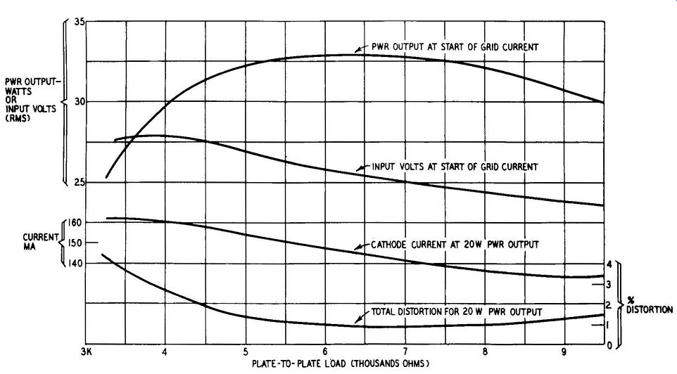
Fig. 508. Power output as related to plate-to-plate loads in Ultra-Linear
operation.
Assume that it is decided to have a total distortion content of only 1 %, which on the face of it seems a pretty good specification.
This corresponds with an output power of 31.5 watts, so there appears to be 1.5 watts in hand. This lines up with an input voltage of 43.5 rms, and that has a peak value of 61.5 volts. Now look at the harmonic analysis of the total distortion. It is a very great help to designers that tube manufacturers have got into the habit of providing harmonic-distortion curves of output tubes since hi-fi became a force in the land. They don't print these data sheets just to make the tube handbooks bulkier; the curves are put there to be used, and used they must be if an amplifier is going to be good to listen to at high levels.
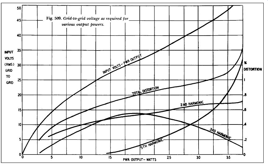
Fig. 509. Grid-to-grid voltage as required for various output powers.
With the nominal output of 20 watts, the peak input of 45 volts develops 0.6% fifth-harmonic distortion at 32.5 watts output and the peak output for a nominal 30-watt amplifier will be right off the diagram. Fifth-harmonic distortion is the very devil. The ear is fairly accommodating to second and third, but even 0.5% fifth harmonic is intolerable to a musical ear. An input of 54 volts, gives nearly 1.3% fifth-harmonic distortion and a peak input of 61 volts would result in unbearable reproduction from a natural sounding point of hearing. The curves of Fig. 509 have been ex tended to the right only sufficiently to show that at powers in excess of about 30 watts the distortion gets out of hand.
This being so, it may be asked why even 0.6% fifth harmonic is considered acceptable for the present design. The answer is, of course, that further feedback will be applied to the amplifier to reduce this. The fifth-harmonic distortion, as the principle component of the total distortion at high outputs, will be reduced most but, if the amplifier is supposed to have a 30-watt (or even greater) output, a considerable amount of feedback will have to be used. \Ve are back to what has been pointed out several times that the function of feedback is to improve an existing good amplifier, not to convert a bad one into something that can be listened to. Designs, therefore, which claim high output powers "with less than l % total distortion" must be considered on their innate merits. And if the total distortion is mostly fifth harmonic, it wi11 sound pretty bad to a keen pair of ears, even with considerable feedback. The present design contains 0.6% fifth (peak) and feedback will reduce it to about 0.2%, a just acceptable figure.
If the distortion without feedback is something like 2%, feedback cannot reduce it to an acceptable figure unless most of the amplifier gain is reduced to an absurdly small amount. With which thought the discussion of the amplifier design can be resumed.
As overall negative feedback will be used, it is necessary to provide more gain in the voltage amplifier than would be required without feedback, if the input to the whole amplifier is to be kept reasonably small. The aim is to keep the number of stages at a minimum and the amplification per stage at a mini mum. A no-gain phase inverter, therefore, seems undesirable, and so the cathode-coupled phase inverter is adopted. In constructing the prototype amplifier to prove the design under discussion, the writer happened to have on hand the Mullard high-mu double triode ECC83 and this was found to be eminently satisfactory.
The American equivalent (12AX7) would be equally suitable.
The first stage should be a pentode both on the score of high gain and freedom from distortion. Unfortunately, quite a number of pentodes are noisy and liable to introduce hum. Within the writer's experience the lowest-noise pentode he has met is the Mullard EF86, which was developed several years ago for critical amplifier positions. The amplifier has a high gain and any noise or hum generated in the first-stage grid circuit will become un bearable in the output. Just any old pentode will not do; it must be genuinely designed for low noise.
As will be seen when the section on feedback is read, the basic cause of instability is. due to phase change in the amplifier trans forming negative into positive feedback. This is best avoided by reducing the number of stages to the minimum and reducing the R-C networks, too ( in number but not in time constant). An excellent way of doing this is to use direct coupling between tubes and, as the cathode-coupled phase inverter conveniently lends it self to this, the first amplifying stage is direct-coupled to the phase inverter.
The output transformer must have been designed for Ultra Linear operation and the taps for the screens must be at 43% of each half of the primary winding. Suitable components are avail able from Aero, Dyna Co., Partridge and others. The power pack is not shown in the circuit diagram (Fig. 507) but any good design will prove satisfactory, particularly if voltage stabilization has been included. The smoothed voltage output must be 440, with a cur rent of rather more than 140 ma, to which, of course, must be added the current required for operation of the tone control pre amplifier, recording amplifier, radio unit, etc. For the usual 500 volt 250-ma rectifier tube, capacitor-loaded, a power transformer secondary of 410-0-410 volts with a capacitor of 8 uf will prove just right. This allows for a 25-volt drop across the smoothing choke, which should have a maximum resistance of 200 ohms and an inductance of at least 10 henries at 180 ma.
Fig. 510 may now be considered in some detail. Starting at the input, capacitor Cx is not required if the preamplifier includes a coupling capacitor after the last tube's plate. If the amplifier were fed with a transducer having continuity to de, the grid circuit of the first tube would be short-circuited if Cx were not there.
Resistor Rx serves to reduce the input to the amplifier. The two resistors Rx and R1 form a potentiometer and could be replaced by a I-megohm volume control. The amplifier has a sensitivity such that an input of 220 mv gives an output of 20 watts, and 300 mv-input just produces overload (in terms of the distortion discussed earlier). If the normal output of the preamplifier, including its tone control circuits, is greater than 220 mv, then Rx should be of such value as just to fully load the amplifier. It is assumed that the volume control will be located in the preamplifier.
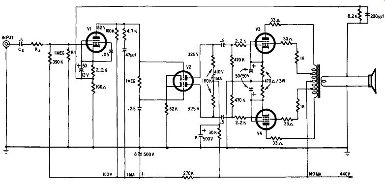
Fig. 510. The complete amplifier less power supply.
As the first tube (EF86) has been chosen for low noise, 1t 1s clearly absurd to introduce noise from other components. All resistors associated with the first stage should be deposited-carbon high-stability type, as also should the feedback resistor of 8,200 ohms. The noise level in the amplifier is 90 db below 20 watts, and the use of ordinary carbon resistors in the first stage could reduce this figure appreciably. It seems a pity to "spoil the ship for a ha'p'orth of tar." The 4,700-ohm 47-uuf network shunting the plate load resistor of the first tube requires some explanation. In Section 7 it is pointed out that an amplifier to which adequate feedback is to be applied must have a very much wider frequency response than would seem to be necessary. Specially designed bass and treble cutoff circuits are required beyond the postulated range. In the bass this is required to prevent the passage of positive feedback caused by phase change of negative, but the present design has very little bass phase change because it has direct coupling and few stages. In the extreme top, however, a cut is needed since there is a tendency for the amplifier to be too good for the application of feedback. Accordingly the supersonic treble is cut by the treble cut network shown. In the performance curves of Fig. 511, it will be seen there is an upward trend in the phase change between 10,-000 and 100,000 cycles although far below instability even at 100,000. ·without the treble-cut network this would be greater, but it will be seen that the frequency response of the amplifier is not impaired, for it is virtually up to the 100,000-cycle value.
The phase-inverter plate-load resistors, the coupling capacitors and the grid resistors of the output stage should be closely matched. Their exact value is not critical but they should be matched. In the event of resistors not being dead-matched, the slightly higher values should be included in the circuits associated with that half of the phase inverter which is direct-coupled to the plate of the first stage.
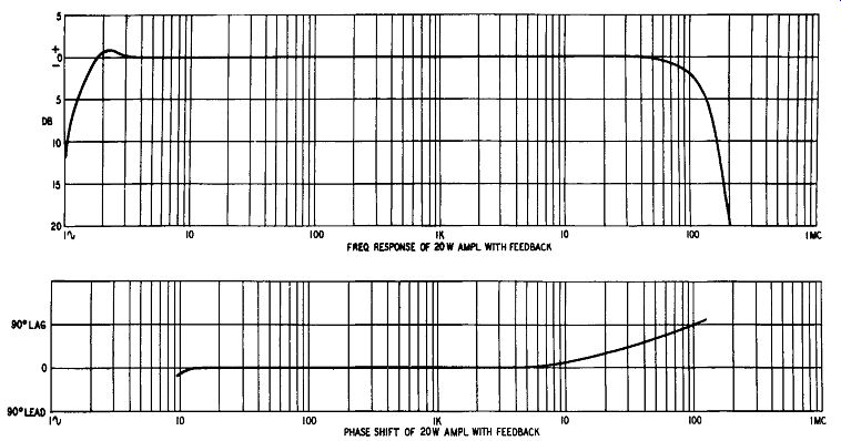
Fig. 511. Performance curves for the amplifier of Fig. 510.
The bypass capacitors of the output stage bias resistors are necessary because a common bias resistor is not practicable with the inherent feedback characteristics of distributed-load working. It is inevitable, therefore, that in this design there will have to be a time constant in the cathode circuits of the output tubes.
Whether this matters or not can be disposed of by examining the output trace on an oscilloscope with square-wave input. In the present design it does not matter.
The 33-ohm resistors shown connected to the plates and screens of the output tubes are a foible of the present writer. Acting as high-frequency oscillation stoppers, they should be as small as possible and soldered directly to the appropriate pins of the tube sockets. They may not be necessary, but high-efficiency output tubes are prone to oscillate at supersonic frequencies and the stoppers can do a useful job without impairing the performance of the amplifier.