WHETHER you build a cabinet yourself, turn the job over to a cabinet maker or buy it ready-made, it is best to know some thing about how furniture is constructed.
There are tricks in every trade, and to start a project without knowing about them is perilous at best. For those who want to buy, remember that some very pretty packages can conceal shoddy or mediocre products. By knowing how good furniture is made you'll be able to be sure that you get your money's worth.
Layout
Before purchasing materials, work out a cutting diagram. This is a miniature layout, to scale, of how you will cut the pieces of your cabinet from the large sheets of raw material. If you've bought a set of plans a cutting diagram is probably included. If not, or if you are starting from scratch, you'll have to make your own.
Consult your plans, and list every part required in categories according to the materials required. For example, some parts will be of ¾-inch plywood, others, such as backs or control panels, may be ¼ -inch. Still others such as molding or legs, may be solid hardwood and you may require, in addition, some solid soft pine for cleats or glue blocks.
The parts for which a cutting diagram is normally needed are plywood. You need it to be sure that you have enough material for all parts, and to make economical use of your material. Too, the cutting diagram helps to keep the grain of the wood running in the right direction on each piece.
Fig. 601. The final working or cutting diagram (shown on page 164 and
above) is laid out on the plywood sheets.
Cut pieces of paper to a scale of, say ¼-inch to the foot, representing every piece of wood you'll need. Then lay them over a rectangle drawn to the same scale and representing an uncut ply wood panel. Try a rectangle representing a 4 x 8-foot panel first, since this is the most common stock size. For a big cabinet you may need more than one panel to get all the parts in and keep the grain running in the right direction. With a small cabinet, you can get them all in one piece with space to spare. In this instance try a smaller stock-size panel, 3 x 8, 3 x 6 or 4 x 6 feet, and see if you can still get them all in. The smaller the plywood panel the less it will cost. Sometimes a set of parts that will not quite make it on one 4 x 8-foot panel will go very comfortably on two 3 x 6's.
Try various combinations until you find the most economical arrangement.
Be careful at this stage to lay out every part with the grain running in the correct direction. The easiest way to keep track of grain is to put an arrow showing direction on each piece of paper representing a part of the cabinet. When making experimental layouts, be sure that this arrow is parallel to one of the long sides of the rectangle representing the panel. The grain on all plywood panels, except counter-front panels, runs parallel to the long sides.
Except in special graining effects, the general rule is that the grain shall run parallel to the longest dimension of a given piece of the cabinet. For example, it will run side to side across the top of a cabinet--not front to back. It will run top to bottom on the sides. However, grain may be either top to bottom or side to side on doors or drop fronts, depending on the effect desired and on the proportions of the cabinet as they influence the proportions of the doors. On a door 2 feet high by 1 foot wide the grain will usually run top to bottom; on a drop front 3 feet wide by 10 inches high it would generally be side to side.
After experimenting with and repositioning the parts until you have located them on the panel diagram, finish your arrangement by either pasting the patterns to the diagram or drawing them in (Fig. 601 ). Be sure to label each individual part.
An experienced cabinet maker may not need to lay out all parts full scale on a panel before he starts cutting. But if you ...
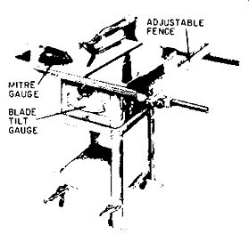
Fig, 602, The table
saw (tilting arbor circular saw) complete with adjustable fence and
mitre gauge. (Courtesy Delta Power Tool Div., Rockwell Manufacturing
Co.)
... haven't done much of this sort of work, drawing every part out full scale on the panel before starting to cut is essential for accuracy and economy. Remember to allow ½ s inch between the parts for the thickness of the saw cut. The pile of sawdust that will accumulate on the floor will no longer be part of your material. It has to come from somewhere!
Cutting
A hand saw is neither the best nor the most accurate way of cutting a large plywood cabinet panel. Machines do this kind of job better and faster.
Table saw
There are two kinds of cuts you may have to make: straight, and curved. For straight cuts, three methods are worth considering, two good and one fair. The first and preferable method is to use a table saw. The saw (Fig. 602) consists of a circular blade with teeth set around its circumference. The blade is mounted under a heavy steel table in such a way that it protrudes up through a slot in the table top. It is rotated from below by an electric motor.
Cutting with this type of saw is done by moving the work across the table top and past the rotating blade, which remains in a…
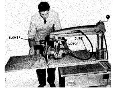
Fig. 603. The swing saw is a useful and easily manipulated tool. (Courtesy
De Walt Inc., Div. American Machine and Foundry.)
… fixed position. The saw blade may be raised or lowered, depending on the depth of cut required, and can also be tilted, allowing the cut to be vertical or beveled at any angle up to 45°. To cut, say, a strip 16 inches wide by 8 feet long from a panel 4 X 8 feet, some sort of device must guide the work past the saw to keep the cut straight and maintain an even width. This function is performed by a "fence" mounted parallel to the saw on one side and adjustable to various distances from it.
A table saw is also equipped with a mitre guide for cutting various angles on the ends of narrow strips of wood. You would use it to cut the 45° angles on the ends of molding to make a frame, or to cut a 10° angle on the end of a stretcher before attaching an angled leg, or to cut off an angle at the top of the leg itself.
A table saw will cut only straight lines. You cannot cut curves with it. But straight-line cuts at all sorts of angles to each other can be made with the use of appropriate guides and jigs, and these cuts can be simultaneously beveled at any angle up to 45°. Also, by proper adjustment of the saw-blade height, it is possible, instead of cutting through a piece of wood, merely to cut a groove in it.
The width of the groove can be altered by the use of various dado blades.
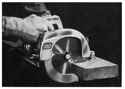
Fig. 604. The portable rotary saw can be used for cabinet work provided
a suitable guide and the proper blade are obtained. (Courtesy Porter-Cable.)
Use a table-or any other saw--Only for the type of work for which it was designed. Any machine is safe when doing its proper work with proper safeguards. Improper operation can cause an accident to the user or the machine!
Overarm or swing saw
Also widely used to make straight cuts is the over-arm or swing saw (Fig. 603). The swing saw has a circular blade similar to that of a table saw, but it operates differently--the table saw works from beneath the material to be cut, the swing saw cuts from above.
The swing saw will handle long rips, cross cuts, bevels, dadoes and grooves just as accurately as a table saw. It will also do some jobs such as routing that cannot be done on a table saw. There is, however, one serious limitation to an over-arm saw. The length of the arm limits the width of rips or cross cuts that can be made.
(A table saw does not have this limitation.) It is one that is inherent in the design of an over-arm saw, but there are ways of working around it. You might, for instance, have to make a wide cross cut in two passes with a swing saw where you could have done it in one with a table saw.
Portable rotary saw
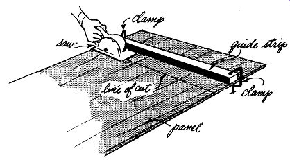
Fig. 605. A guide for the rotary saw is easily made from a strip of
wood.
A portable rotary saw (Fig. 604) is really made for on-the-job carpentry, not cabinet work, but by using the right blade and feeding the machine carefully, it is possible to make a nice clean cut. The problem is to keep your cut straight in comparison with the cut you can get with a table or swing saw. It cannot be done by eye. Clamp a straight strip of wood to the panel to act as a guide for the shoe of the portable machine (Fig. 605). Be certain the guide piece is really straight; your cut can be only as straight as the guide.
Because of space limitations, the only practical way of cutting a large panel might be by use of a portable saw. If possible, however, try a table or swing saw.
Band saw
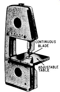
Fig. 606. The band saw is especially suitable for cutting curves. (Courtesy
Delta Power Tool Div., Rockwell Manufacturing Co.)
The saws mentioned thus far are designed strictly for straight line cuts. But what happens if you need to cut a curve? For this you have a choice of three other types. The fastest and most powerful is a band saw (Fig. 606). Simply described, it consists of a pair of large pulleys or drums. One is placed above the other and a long continuous saw blade that resembles a belt runs around both drums. A small steel table is placed between the drums as a rest for the work, and the saw blade passes through the middle of the table. The blade is narrow and made of very thin steel, permitting it to cut quite sharp curves as well as long flowing ones without binding the blade. The table is adjustable, making it possible to cut curves and bevels simultaneously, a feature that is often desirable. A band saw should be treated with extreme caution and respect. Very fast and powerful, they can m1ure a careless operator before he is aware of what has happened.
Sabre saw
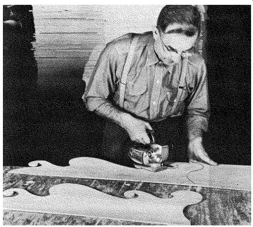
Fig. 607. The sabre saw is another machine which is excellent for cutting
curves. (Courtesy Porter-Cable.)
Another good machine for cutting curves is the sabre saw (Fig. 607). For cutting a long curve, say along the front of a cabinet top, it is slower than a band saw, but it is also much more compact, less expensive, and therefore much more likely to be available to the home craftsman.
The sabre saw is portable and cuts by means of a blade that moves alternately up and down like the movement of a hand saw, except that it cuts on the up instead of the downstroke. About half a dozen good makes are on the market, hut only a few will simultaneously cut a bevel.
The smoothness and accuracy of a cut with this type of machine depends on how keen an eye you have and the steadiness of your hand. Practice on scrap wood before starting to do serious work. The sabre saw is a fine tool for making the cutouts for the tuner and amplifier in control panels and for record players or tape machines in mounting boards. If you have any large ventilation holes to cut in your cabinet, the sabre is excellent for this purpose and it is also a fine tool for cutting speaker holes and ports in baffle boards.
Power jig saw
A third type of machine for curved cuts is a power jig saw (Fig. 608). Although they will make a nice clean cut, they are slow.
Between sabre and power-jig saws, a sabre is preferable. A jig saw, however, will do the job.
Jointing
When your basic pieces of material have been cut to size, it is time to prepare the ends for the joints that will form the assembly.
So let's look at the types of joints in common use, and see how they are made. We will start with those that form the "basic case"--the top, sides, bottom and any fixed internal partitions.
Butt joint
The simplest method for joining two pieces of wood to form a corner is called a butt joint (Fig. 609) It is formed very simply by overlapping the end of one piece over the end of the other.
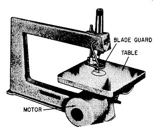
Fig. 608. Another useful machine for curved work is the power jig saw.
(Courtesy Delta Power Tool Div., Rockwell Manufacturing Co.)
To have any strength at all this joint must be fastened, first with glue and then with screws or nails.
This is the simplest type of joint, but also the weakest. All that is required to make a reasonably tight clean joint of this type is a good straight smooth cut on each of the ends to be joined. No special machining is required. Ends satisfactory for butt joining can be done with very modest equipment, making this the joint of choice when facilities are limited.
The disadvantage of the plain butt joint, in addition to weakness, is that the entire end grain of the overlapping piece is exposed. It is impossible to finish this end grain so that it will conform to the lengthwise grain of the rest of the side. If veneer cored plywood has been used, the end grain can be particularly obnoxious.
Shoulder butt joint
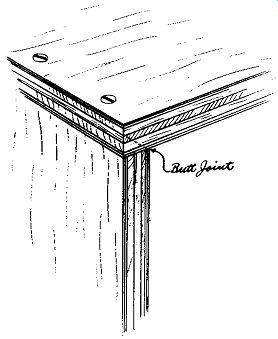
Fig. 609. One of the simplest methods of joining wood is the butt joint.
A considerable improvement over the plain butt joint is the shoulder butt joint (Fig. 610). It is formed in the same manner as a plain butt except that the overlapping panel is notched to receive the end of the other panel. As you can see, panel 1 now bears against two surfaces, forming an L in the end of panel 2, instead of a single flat surface. This considerably increases the strength of the joint and also improves the appearance since much less of the end grain of panel 2 is left showing. This joint is not really much more complicated to make than a plain butt. The notches can be made on a table or a swing saw. They can even be made with a portable rotary saw since it is adjustable for depth of cut, but the problem remains of accurate guidance of the saw.
Your solution will again be to clamp on a guide strip.
Double-shouldered butt joint
The next joint is not frequently used. It is a further variation of the shoulder butt, and could be defined as a "double-shouldered butt." (Fig. 611). The ends of both pieces to be joined are notched and are butted together with the notches interlocked. This joint has more strength than a normal shoulder butt since the pieces being joined bear against each other on three surfaces. However, it is not as popular as it might be, possibly because the notches in both pieces must be very accurate to form a good tight joint.
Most constructors with skill and equipment adequate to handle this joint can also handle mitres, and mitres do make a cleaner looking job.
Mitre joint
The mitre joint involves cutting the ends of both pieces to be joined at a 45° angle and then fitting the angled surfaces to...
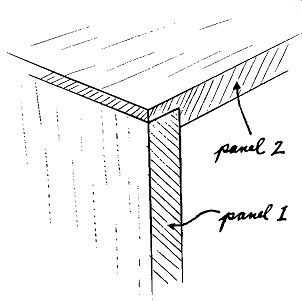
Fig. 610. The shoulder butt joint is stronger than the plain butt and
makes finishing easier by eliminating much of the exposed end-grain of
the wood.
...form a corner. In good-quality furniture, variations of this joint are standard procedure (Figs. 612-a,-b,-c). The mitre joint can be strengthened or reinforced in several ways. The least effective is to add only glue blocks on the inside (Fig. 612-b).
Mitre and spline
Far superior to this is the "mitre and spline" variation. A spline of wood or metal is inserted to run down the length of the joint and at right angles to it. The spline is fitted in grooves cut in each piece before joining (Fig. 612-c).
A common variation of the mitre and spline is the use of clamp nails. These actually constitute partial splines, being inserted at each end of the joint and at right angles to it like a spline, the difference being that they run in only about 3 inches from each end.
All of the joints we have seen thus far can be made on either a table or a swing saw. However, for mitres a shaper (Fig. 613) is preferred. A shaper consists of a steel table with a spindle sticking up in the middle of it. Various types of cutting knives can be attached to this spindle, and guides are provided for passing the work by the knives. The shaper leaves a much smoother surface where it has cut than does a saw; therefore, the mitres will be cleaner and tighter.
Lock mitre
Another effective variation of the mitre joint is known as a "lock mitre" (Fig. 614). The lock, of course, refers to the tongue ...
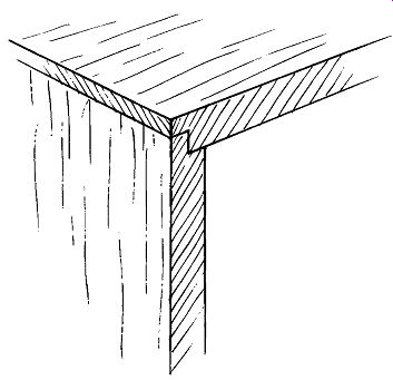
Fig.
611. The double-shouldered butt-joint, although stronger than the shoulder-butt,
is not often used. Its complexity defeats its advantages.
... and-groove arrangement inside the mitre. This joint is the strongest and the best of the variations, but to make it you need a shaper with special cutter knives. Don't try a lock mitre unless you have a shaper. However, if you are having a shop make your cabinets, try to get them to put your units together using this joint wherever possible.
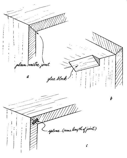
Fig. 612. The mitre joint and methods of rein forcing it: a) plain mitre;
b) use of glue block; c) spline used to strengthen joint.
Mitred shoulder butt
The last variation of the mitre joint is really a mitred shoulder butt (Fig. 615). It looks rather similar to a lock mitre except that there are two flat surfaces inside the joint instead of the tongue and groove. This joint is also best made on a shaper, but it can be done with a table or swing saw. It is, perhaps, a bit more difficult to make than a mitre and spline, and is not quite as strong.
Not only the plain mitre, but also any of the other joints from a plain butt on up can be reinforced with glue blocks on the inside. It is particularly advisable to do this in speaker enclosures as it will considerably improve the resistance of such joints to failure resulting from the vibration inevitably set up in the cabinet by the speaker.
It is possible literally to shake a cabinet apart, even a lock mitred one, with speaker vibrations. To do this you would have to feed a pure tone of the right frequency into the speaker at a high level for a long time. You are not likely to do this, but it does illustrate the point that strains of a sizable magnitude are set up in a speaker enclosure. Internal reinforcing of the joints helps to extend the service life of the unit.
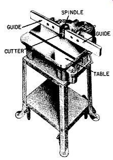
Fig. 613. A shaper is an ideal tool for use with the various forms of
mitre joints. (Courtesy Delta Power Tool Div., Rockwell Manufacturing
Co.)
Partitions
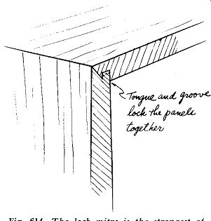
Fig. 614. The lock mitre is the strongest of the variations, but a shaper
is essential if this joint is to be prepared properly.
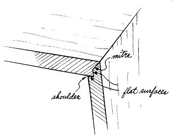
Fig. 615. The mitred shoulder butt is similar to a lock mitre, but is
not quite as strong.
So, you've enough joints now to make corners, but suppose the design calls for some fixed internal partitions such as shelves or record dividers. There are three common ways of installing such parts. The most obvious and again the least desirable is a plain butt (Fig. 616). No special machining beyond a smooth straight cut on each end of the partitioning piece is required.
There are, however, two better ways of fixing a permanent partition in a cabinet. In both cases dadoes are used (Figs. 617-a,-b). Let us suppose we want to install a fixed shelf. One method is to cut a groove on the inside face of each cabinet side at the proper height, to a depth of about half the thickness of the side panels and of a width corresponding to the thickness of the shelf. Assuming ¾-inch plywood is being used, the grooves or dadoes in the sides would be 3/8-inch deep and ¾-inch wide to receive the ends of the shelf. The dadoes can be cut on a table or swing saw or with a portable saw, and should be cut before any parts are assembled. Should it become necessary due to a change in plans to cut such grooves after assembly of the basic case this can be done by using a portable router (Fig. 618), which can also be used alternately on unassembled parts. This, by the way, is also an excellent tool for making tuner record player or speaker cutouts in place of a sabre saw since it will route curves as well as straight lines and is adjustable for depth of cut. It is, however, an expensive machine and, therefore, like the shaper, more likely to be found in a professional shop than in the home. If you should need one for a specific job, you could probably rent one by the day.
The dadoed shelf is vastly stronger than a butted one. With the full dado as described, only the cabinet sides are machined. The shelf need only be cut to the correct length. There is another method of dadoing a shelf or partition which involves machining both the partition and the cabinet. In this case the dado in the cabinet is only ¼ to ¼-inch wide and ¼-inch deep, and tongues are machined on the ends of the partition to fit. We are still thinking in terms of ¾-inch plywood.
There is little to choose between the two latter methods as far as strength goes, except that the narrower groove weakens the cabinet side panels less. The wide groove method is less work, however.
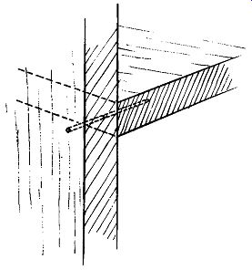
Fig. 616. Internal partitions can be fixed in place with plain butt
joints.
However, this is the least desirable method.
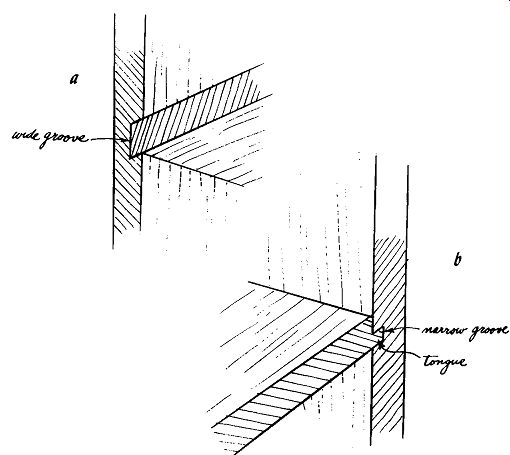
Fig. 617. Two ways of inserting a fixed partition in a cabinet: a) full
dado; b) partial dado or tongue and groove.
Now you know enough joints to put the entire cabinet together by enough different methods to account for considerable variations in available equipment. You can also choose the correct joint for any moldings. Whether you are planning to put a molding around a top or bottom or a frame around a front, you'll generally mitre it at the corners. In such places you would use a plain mitre. There is no need for splines or locks.
Except for a few contingencies you are quite well equipped. But suppose you wanted to make a frame with legs at the four corners to form a base on which to stand a cabinet, and the design calls for the legs to be the corners of the base. Or suppose you need to make a door of, say, American Colonial style that consists of a frame with an inset panel, and the corners of the frame are not mitred. They would both be handled by one of two alternate methods. One is a doweled joint, and the other is a mortise-and tenon joint.
Doweling
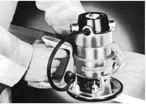
Fig. 618. A portable router is useful for last minute shaping operations.
Let's look at doweling first. It is the easier of the two. We'll say you want to dowel a stretcher to a leg to form a corner for a base. The stretcher is ¾-inch material so you will need ¾-inch dowels. Depending on the width of the stretcher, drill either two or three holes ¾-inch in diameter and about ¾-inch deep in the end of the stretcher, and corresponding ¼-inch holes in the leg.
In a 2-inch wide stretcher use two dowels. If the stretcher is 3 or 3½-inches wide, use three dowels. Cut the dowels off to a hair under 1 ½-inches long, put glue in the holes in both stretcher and leg, insert the dowels in place so that they go through from the stretcher into the leg, and clamp the whole thing to dry (Fig. 619).
To dowel a door frame, the procedure is the same. Matching holes are drilled in the upright and cross piece, glue and dowels inserted, and the assembled frame clamped to dry (Fig. 620). The real trick in doweling is to get the holes for the dowels in both pieces, say a stretcher and a leg, lined up exactly with each other. If the dowel holes do not match precisely as to size, location and angle, assembly will be impossible. Unless you are a real Deadeye Dick, don't try to drill the holes with an unmounted hand drill. You'll think you are doing fine until you discover that ...
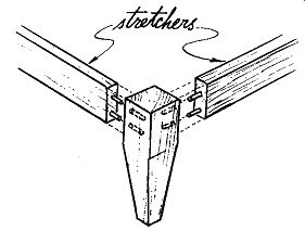
Fig. 619. Doweling is a must when assembling weight bearing structures
such as the leg and stretchers illustrated.
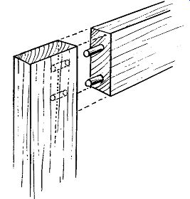
Fig. 620. Doweling a door frame follows much the same procedure as used
in Fig. 619.
... an error of even 1/32-inch in centering a hole or an angular error of 2° to 3° is too much.
Mortise and tenon
Now suppose we take the same stretcher and leg arrangement, but this time the joint is to be a mortise and tenon. The tenon is a fancy name for a wood tongue that is cut on the end of the stretcher and is rectangular in shape (Fig. 621 ). The mortise is the matching rectangular hole in the leg and is cut with a special mortising chisel. The tenon is glued into the mortise to make a firm joint. Occasionally, a locking pin or dowel is driven in at right angles to lock the tenon in place when a great deal of strain is expected.
The mortise and tenon must form a tight fit for the joint to have any strength, so they must each be cut very accurately. However, properly done, a mortise-and-tenon joint is stronger than a doweled joint, partly because a larger area of material is involved in forming the connecting linkage of the joint and partly because this same connecting piece needs to rely on glue on only one side of the joint.
Assembly
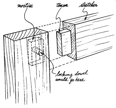
Fig. 621. The mortise and tenon joint, although a bit more difficult
to handle, is much stronger than the doweled joint.
Up until now about all you can see to show for the work you have done is a pile of small pieces of wood where there were one or two big ones before. This is pretty uninspiring, but once you start to assemble you will see results in a hurry.
Assembly starts with the basic case; that is top, bottom, sides and any fixed internal partitions, either horizontal or vertical. For the moment forget the doors, drawers and other parts that are detachable from the main case.
The parts for your main case have been machined at the ends for whatever type of joints you want to use--butts, shoulder butts, mitre and spline or whatever. They've also been dadoed where necessary to take the ends of fixed partitions. Now place these parts in their proper positions relative to each other, and hold them in place with braces or tape while you make a trial assembly to see if your cutting is good, your joints fit well and your dimensioning was correct. If you did make any errors, this is the time when they will show up because the case just won't go together.
But let's assume that everything fits. You are then ready to glue the ends and make the assembly permanent.
Gluing
Here are a couple of tips in gluing. When two pieces of wood are to be fastened, glue should be applied to both. Putting a great slobber of glue on one piece and nothing on the other is not good practice. It tends to cause uneven spreading of the glue and, therefore, an unreliable joint. To get an even distribution, apply the glue with a brush uniformly over the surface to be joined.
Do not put on too much glue--a very common mistake. When you clamp for drying, the excess glue will come squirting out of the joint and get on your panels. Areas smeared with glue that has been allowed to dry will not take stain and, if you intend to leave your wood color natural, the glue may discolor it. A little excess glue should come out of a properly glued joint when clamped, but not much.
In the second place, a joint with too much glue in it is a weak joint. The strength of a glued joint comes from the combination and interlocking of the glue with the wood fibers. Glue alone, when dry, is a rather weak, brittle substance, so if a heavy layer of glue dries between two pieces of wood, the joint will be weakened.
Most glues penetrate better when warm than when cold. If they are very cold, they will not penetrate at all. When you heat glue, it will seem to thin out appreciably. This is fine, because it is easier to apply the kind of thin uniform coat that is desirable.
Glue sets well only under pressure. This means that, after the pieces are glued and joined the entire assembly should be set in clamps while the glue dries (Fig. 622). This is best done with cabinetmaker's pipe or bar clamps. The more clamps, the more uniform the pressure and the better the joints will be.
When the cabinet is clamped, check the corners with a carpenter's square to be sure that they are really right angles. If they are a little off, now is the time to correct them. If the cabinet is a little out of square, once the glue has set it will be that way permanently. This creates problems when trying to fit doors or drawers.
Fitting and edging
From here on, for a while, the sequence of events is dictated by the requirements of the specific design chosen. In one case ...
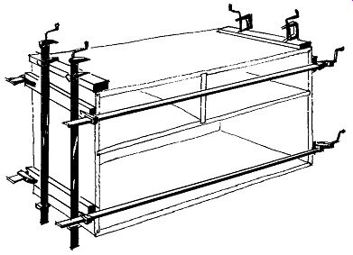
Fig. 622. Joints that are glued must be clamped under pressure
so that the glue sets properly.
... it may be necessary to do certain edging before it is possible to start fitting, while in another instance the fitting should come ahead of edging. Sometimes it is best to install at least part of the hardware, such as hinges on doors, prior to fitting. Only the constructor can figure out the proper sequence for each job after studying what is involved.
Edging is any form of veneer, stripping or molding used to cover the raw end grain of plywood left showing around, say, the front edges of the cabinet or the edges of doors or drawer fronts (Figs. 623-a,-b illustrate veneer and molding.). Edging may also be applied for purely decorative or styling reasons.
Except in speaker enclosures, where moldings are often used around the fronts as stops against which to press the speaker baffle boards from inside, edging has no structural importance. With few exceptions it is used purely for appearance.
On period styles the edging may take the form of elaborate decorative moldings that are often identifying characteristics of particular periods. Given a basic structure, the final overall appearance can be profoundly altered by variations in this kind of decorative detail.
Most edging, whether veneer, facing strip or molding, is applied in about the same manner. First, the end grain to be surfaced is carefully smoothed with a plane or sandpaper to eliminate any lumps or bumps that might prevent the edging from lying flat against it. (In a cabinetmaking shop, edges that will later need to be surfaced are run through a planer prior to assembly of the cabinet.) With the surfaces prepared, the edging is cut to the proper lengths, mitred for corners where necessary, then glued and clamped in place while the glue sets.
Facing strips and moldings are sometimes held with very fine wire brads in addition to the glue. After the brads are inserted the resulting small holes must be filled and sanded.
Always fit doors or drawer fronts prior to veneering the edges.
If an edge is already veneered and must be planed to fit the door, the first thing you'll plane off is the veneer--in which case you've got to veneer it all over again.
Some methods of edging involve machining the end grain beforehand. One such method is the use of a V facing strip (Fig. 623-c). This type of stripping is triangular in cross-section and is glued into a V-shaped slot that must be machined into the edge of the plywood prior to assembly. This gives a very durable edge and eliminates the possibility of the ripples that sometimes occur with veneering. The method is, however, somewhat laborious and not recommended for the beginner.
Another method requiring pre-machining is the use of T-shaped facing strips (Fig. 623-d). Actually, this is sometimes done with facing strips and sometimes with moldings, but in either case the edging material has a tongue in the back that fits into a groove previously machined into the end grain of the plywood. This method increases the holding power of the edging very nicely.
Fitting is nothing but a series of minor adjustments to doors, drawer fronts, lids, control panels, baffle boards, backs and so on.
Such adjustments account for minor variations in thickness or straightness in the panels forming the openings in which these various pieces are to be placed. Fitting is really a process of cut and try. With a drawer front, for example, you would mount the drawer on its tracks and the front on the drawer. Then just try sliding it in and out to see if it fits. If it binds somewhere, find out where and determine whether the front should be realigned on the drawer or if it just needs to be planed off a bit. If it needs planing, take off very little at a time and keep trying it until it fits.
On occasion a drawer may bind, not because it doesn't fit, but because the drawer slides are a trifle out of alignment. Make sure this isn't the trouble before planing a door that doesn't need it.
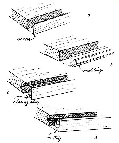
Fig. 623. Edging is available in a variety of forms: a) simple veneer
stripping; b) decorative molding; c) V facing strip; d) T facing strip.
With doors or drop fronts, set in the hinges before your start fitting. They may have to be taken off again if the hinge side needs planing, but you won't get an accurate fit without them.
With twin doors, hinge and fit one side first, then hinge and fit the other side to it.
Control panels and baffle boards need not be extremely accurate (just as long as you can get them in and out) because they are usually covered by a molding in front. Be careful with speaker backs, however, to avoid air leaks.
Fitting isn't difficult nor does it require any great skill. It is, however, painstaking and time-consuming work when done properly, because one must be forever careful not to cut away too much. If you do and end with a loose fit, the part will function but it will not look right.
Hardware
A speaker cabinet is not likely to have much in the way of hard ware. A decorative metal grille is not recommended because it
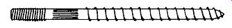
Fig. 624. The hanger bolt is used to mount legs to the cabinet.
often tends to rattle but, if one is used, it goes in after finishing and generally is mounted to the baffle board on top of the grille cloth. Leg ferrules also go on after finishing, to avoid smearing the metal with finishing materials.
Equipment cabinets are likely to require a good deal more in the way of hardware-knobs, catches, drawer slides, lid supports and so on. In addition to hinges, lid supports, slides and catches should be trial mounted during or after fitting to make sure they will align and operate properly. All these must be taken off again for finishing, but must be trial mounted beforehand so that, if you should get one of them in the wrong place and find yourself left with a couple of unwanted screw holes, you can fill and hide them in the finishing process.
Legs and bases
Now that the cabinet is built and the internal parts are all fitted and working properly, the job is almost done. All that is needed is something for it to stand on, and you'll be all set. You might have a cabinet design in which the sides come down below the bottom and form a base. If so, all that is necessary is to put four metal glides on the corners.
But in most cases either legs or a base are needed. Check thoroughly to see if there isn't a stock leg available that will satisfy your needs. Even the large commercial cabinet shops find it preferable to buy their legs rather than make them themselves. The chances are you will too.
Round or turned legs are made on a lathe, while square or square tapered ones can be made, with appropriate jigs, on a table saw. If you haven't a table saw, a square tapered leg can be made ...

Fig. 625. The T-nut is
a special fitting used in conjunction with the hanger bolt.
... with a simple hand plane but, unless you are an expert, you might have a bit of trouble getting two to match, let alone four.
The question is, now, how to put legs on the cabinet. There are several ways of doing this. The most common is to drive what ...
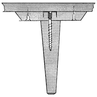
Fig. 626. A mounted
leg showing T-nut, wood plate and hanger bolt.
... is called a hanger bolt into the top of the leg, screw the hanger bolt to a special plate, and screw the plate in turn to the bottom of the cabinet. A hanger bolt is a device threaded to go into wood at one end and metal at the other. It has no head. An average one would be about ¼-inch thick. The thread that goes into the wood is similar to that on a lag bolt. The thread on the other end is a standard machine-screw thread (Fig. 624). Ready-made legs may already have the hanger bolt installed.
If not, be sure to drill an ample pilot hole in the legs before starting to drive the bolts, otherwise you won't get the bolt a half inch into the leg before it will split.
Although legs can be attached to either wood or metal plates, metal ones are more common. Several standard types are available, and it makes no difference which you use so long as you watch out for one thing. There is a plate made for angled legs, and another type for straight legs. Be sure, if you want angled legs, that you do not get straight-leg plates, or vice versa. There is also a type ...
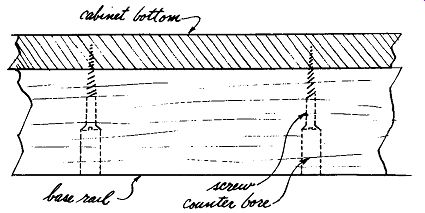
Fig. 627. Method of attaching a base to the cabinet.
... of plate that can be used for either one. In this instance, put the leg into the correct end of the plate for the type of leg you want.
If for some reason you cannot get or do not wish to use metal plates, wooden ones can be made of 3- or 4-inch squares of scrap plywood. Drill a ¾-inch hole in the center for the hanger bolt, and four clearance holes in the corners for the wood screws. A T-nut is used in the center hole. AT-nut is a metal fitting threaded on the inside to take the machine-screw-threaded end of the hanger-bolt (Fig. 625). Tap this piece into the center hole in the wood block, with the threaded tube part down. Now run the hanger bolt on the leg up from underneath into the thread in the T-nut (Fig. 626). A straight leg can also be installed with just a T-nut and hanger bolt, eliminating the plate entirely. To do this, drill the holes for the T-nuts directly into the bottom of the cabinet, install the T-nuts from inside, screw the leg and bolt up from underneath, and you are all set.
Legs can be held by merely driving long wood screws through a plate and down into the top of the leg. They have even been nailed. Neither method is very satisfactory. Stick to the hanger bolt. It is no great trouble and is more likely to be satisfactory.
Next, suppose you have a base. It may rest directly on the floor, or perhaps it is raised off the floor with legs at the corners. In any event it would be attached to the cabinet by wood screws from underneath (Fig. 627). The only consideration here is to use the correct length of screws for the job. If they are too short, they will not go deep enough into the bottom of the cabinet to hold securely; if they are too long, they will come up through the bottom and into the inside of the cabinet.
The bottoms of either legs or bases should be capped with metal or plastic gliders to make movement easy and protect the floor. There are several varieties so pick the type and size suited for your unit. A glider should not be as big or bigger than the leg end. Generally, they are not supposed to show unless they are part of a ferrule, so select a size small enough to be inconspicuous.
Kit construction
You may have occasion to construct a cabinet from a kit, rather than from the raw materials. In such cases, all cutting, jointing and shaping operations will have been performed. You won't have to worry about what type of joint to use where, because the manufacturer has already taken care of this for you.
He will generally also supply you with a working drawing and an exploded view that will enable you to visualize immediately how the whole thing goes together.
Follow the manufacturer's step-by-step instructions. He has put several of these things together, and knows the best method. In working from a kit, you do not have any flexibility as regards varying the design, and you would be wise not to take any liberties. Build it the way the manufacturer intended, and you'll get good results. The finishing and retouching procedures, given in the following sections, apply to kits just as they do to a cabinet that you have constructed from your own design.