| Home | Audio mag. | Stereo Review mag. | High Fidelity mag. | AE/AA mag. |
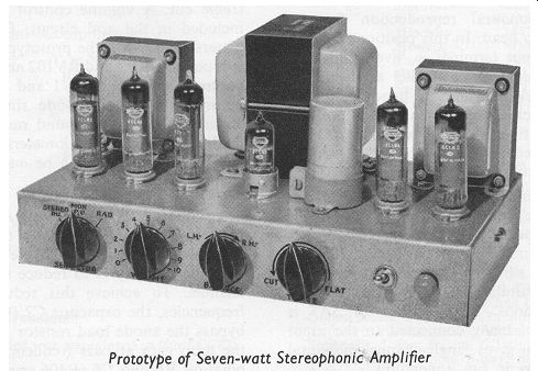
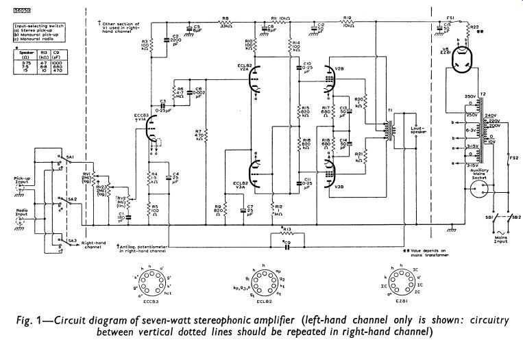
The circuit diagram drawn in Fig. 1 is for a high-quality, dual-channel amplifier designed principally for stereophonic reproduction but also providing facilities for monaural applications.
Only one channel of the amplifier is drawn. The circuitry appearing between the dotted lines is for the left-hand channel: it should be duplicated for the right-hand channel. The circuitry drawn outside the dotted lines (the power supply, for example) is common to both channels.
The total complement of valve (tube) s used in the amplifier consists of one double triode, type ECC83, four triode pentodes, type ECL82, and one full-wave rectifier, type EZ81. The double triode is shared between the two channels, one section of the valve (tube) being used in each channel for voltage amplification. Two of the ECL82 are used in each channel. The triode sections of these valve (tube) s form a phase-splitting stage and the pentode sections are arranged as a push-pull output stage with distributed loading. The EZ81 forms a conventional power supply with resistance-capacitance smoothing, providing the h.t. for both channels.
The rated output-power reserve of each channel is 7W, at which level the total harmonic distortion is always better than 1.0 %. The low level of distortion is achieved by using 21dB of negative feedback, the feedback voltage being taken from the secondary winding of the output transformer in each channel to the cathode circuit of the corresponding input stage. The sensitivity of the circuit, even with this high value of feedback, is 120mV, which is ample for use with existing stereophonic crystal pick-up heads.
-----------
CIRCUIT DESCRIPTION
Resistors and capacitors appearing in the left-hand channel of the amplifier are numbered 1, 2, 3, etc.; the corresponding components in the right-hand channel are numbered 101, 102, 103. etc.
Input Selector Switch
The input stages of both channels are connected to the 3-way selector switch SA. The switch positions indicated in Fig. 1 provide the following facilities:
(a) Stereophonic reproduction from stereophonic crystal pick-up heads.
(b) Dual-channel monaural reproduction from a monaural pick-up head. In this position, the left-hand pick-up input terminal is ‘live', and both channels are connected in parallel at the input. The input terminal for the right-hand channel of a stereophonic pick-up head is earthed at position b of SA2. If position b of SA3 is earthed instead of being connected to position b of SA1, single-channel reproduction is possible.
(c) Dual-channel monaural reproduction from an FM tuner unit.
The input socket in Fig. 1 is connected for monaural applications. If position c of SA3 is connected to the right-hand input terminal instead of the left-hand terminal, the circuit will be suitable for reproducing stereophonic transmissions. If position c of SA3 is earthed instead of being connected to the input socket, the system gives single-channel monaural reproduction from an f. m. tuner unit.
----------- Fig. 1
Input Stage
The triode sections of the ECC83 are used for voltage amplification, one section being used in each channel. A simple treble tone-control network consisting of the components RV2 and C1 (RV102 and C101) is incorporated in the grid circuit giving continuously variable treble cut. A volume control RV1 (RV101) is also included in the grid circuit. Dual-ganged potentiometers are used in the prototype for the tone-control components RV2 and RV102 and also for the volume control components RV1 and RV101, so that equal adjustments can be made simultaneously to both channels. It may be found more convenient to use dual-concentric potentiometers for these controls because adjustments can be made separately to each channel with them.
Instability can result from the large amount of negative feedback introduced to the cathode circuit of each input stage, and the simplest method of ensuring stability is to reduce the loop gain of each channel. To achieve this reduction at high audio frequencies, the capacitor C2 (C102) is connected to bypass the anode load resistor R3 (R103). To reduce the loop gain at bass frequencies, the parallel combination R6 and C6 (R106 and C106) is included in the coupling circuit between the first and second stages of each channel. This manner of coupling results in resistive attenuation at low audio frequencies, so that the phase shift is limited.
Balance Control
To compensate for any differences in acoustical output resulting front unequal outputs from the stereophonic pick-up head or unequal sensitivities of the loudspeakers, a balance control consisting of RV23 and RV123 is incorporated between the volume and tone controls. This is made up of a logarithmic potentiometer connected in reverse in one channel and an antilogarithmic potentiometer connected normally in the other. The characteristics of this control are discussed in Section 4. If dual-concentric potentiometers are used for the volume control RV1, RV101, balance can be achieved with them, and the potentiometers RV23, RV123 can be omitted.
Phase-splitting Stage
The output from the anode of V2A is taken to the grid of V3A by way of the resistors R15 and R12 (R115 and R112). These components also form the grid-leak resistance for the pentode section V2B, and R16 and R12 (R116 and R112) comprise the grid-leak resistance for V3B. Balance between the output voltages from the triodes of the phase-splitter is governed by the values of these three resistors.
Output Stage
The pentode sections of the ECL82 are used in a push-pull output stage. Distributed loading is used, and the primary winding of the output transformer is tapped so that 20 % of the winding in each anode circuit also appears in the corresponding screen-grid circuit.
(The choice of tapping points is discussed in Section 3.)
Negative Feedback
The amount of negative feedback which is used between the secondary winding of the output transformer in each channel to the cathode circuit of the input stage of that channel is 21dB. The output resistance of each channel with this feedback is 0.54 ohm measured at the 15 ohm output terminal. This gives an adequate damping factor of approximately 28.
-----------
Power Supply
A conventional power supply using the Mullard full-wave rectifier; type EZ81, with resistance-capacitance smoothing, provides the h.t. for both channels. Both supply connections are made to the common reservoir capacitor C15, but smoothing is achieved separately in each channel with the components R19, C12 and 8119, C112.
The resistor R22 in the cathode circuit of the EZ81 should, with the transformer resistance, provide the minimum limiting resistance quoted for the valve (tube) . The choice of value for limiting resistors is discussed on page 28. A total h.t. current of 140mA at 278V is required for the amplifier, and the total heater current needed is 4.57A at 6.3V.
A reduction in the number of components is achieved if an h.t. line which is common to both channels is used. The necessary modifications (with reference to Fig. 1) are as follows: R8, R11 and R19 should be decreased to 15, 5.6 and 5.6k-orespectively; C5 and C8 should be increased to 16µF each; R108, R111, R119 and C105, C108, C112 are not required; R103, C102 should be connected to C5; R110 should be connected to C8; R114 should be connected to C12.
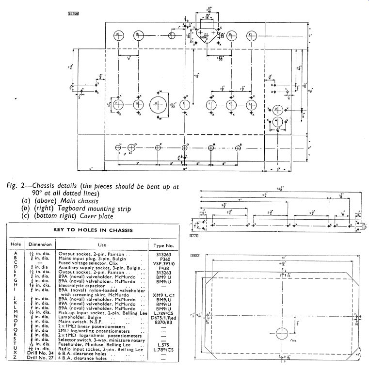
CONSTRUCTION AND ASSEMBLY
The chassis for the 7W stereophonic amplifier is made from three separate pieces of 16 s.w.g. aluminum sheet, The dimensions (in inches) of these pieces are:
(a) Main chassis r 16 x 101 /2
(b) Tagboard mounting strip 12 7 /8 x 1
(c) Cover plate 13 x 7 1 /2
Each piece should be marked as shown in the drawings of Fig. 2, and the holes should be cut as indicated. Where bending is required, it is important that the bends should be made accurately at the lines for the pieces to fit together properly on assembly.
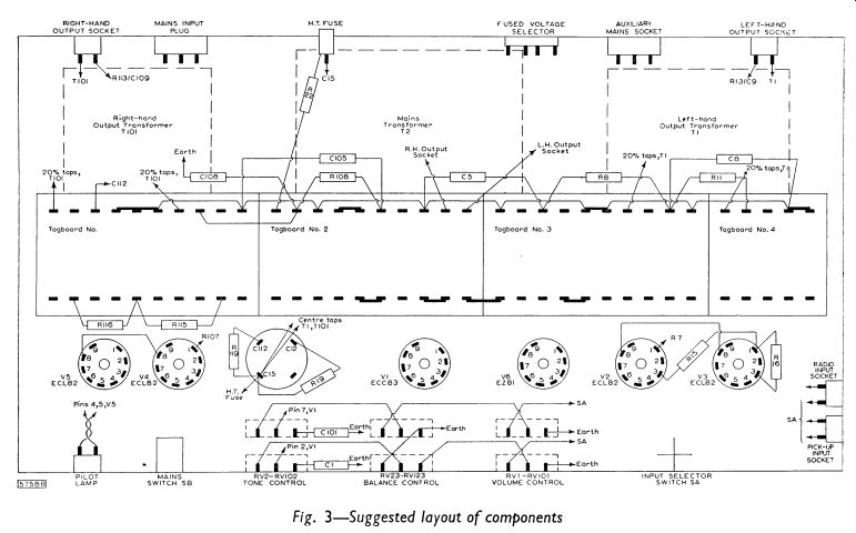
----------- Fig 3
------------
----------
------- Table 1
Most of the smaller components should be mounted o n tagboards, the wiring of which is shown in Figs. 4 to 7, and the tagboards should be fixed to the mounting strip. The larger components such as switches, valve (tube) holders and transformers should be mounted in the chassis in the positions indicated in the layout diagram of Fig. 3. The recommended wiring between these components is also indicated in Fig. 3. It will be seen that the two channels of the amplifier are separate, one channel being in each half of the chassis.
PERFORMANCE
Distortion
The total harmonic distortion was measured in the prototype amplifier with a continuous sine-wave input signal at 400Hz. With 21dB of negative feedback, the distortion for the rated output of 7W per channel is always better than 1.0 %. The variation of distortion with output power is shown in Fig. 9.
Intermodulation distortion, measured with carrier and modulating frequencies of 10KHz and 40Hz respectively, is better than 1.5 °/.
Cross-talk interference is better than 40dB below 7W at 100Hz, 1- khz and 10KHz.
Frequency Response
The frequency-response characteristic of each channel of the prototype amplifier, measured for an output of 1W is shown in Fig. 8.
At 20KHz. the response is 3dB below the level at 1- khz and at 15Hz it is 1.5dB down. The response at the rated output power of 7W is 3dB down at 15Hz.
Sensitivity
The sensitivity of each channel of the circuit (including the controls) with 21dB of negative feedback is 115mV at balance for the rated output of 7W.
Hum and Noise
The level of hum and noise in each channel of the prototype amplifier is better than 60dB below the rated output.
Tone Controls
A continuously variable treble-cut tone control is included in each channel of the amplifier. The characteristic of this control is shown in Fig. 8, from which it can be seen that full application of the control gives about 23d B of cut at 10KHz.
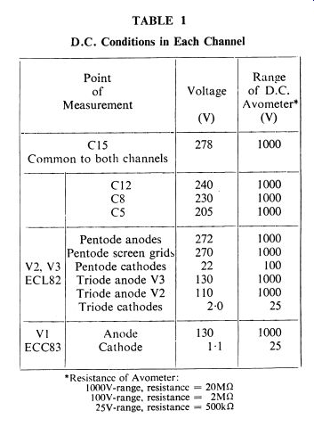
D.C. CONDITIONS
The d.c. voltages in each channel should be tested with reference to Table 1. The results shown in this table were obtained with an Avometer No. 8.