| Home | Audio mag. | Stereo Review mag. | High Fidelity mag. | AE/AA mag. |
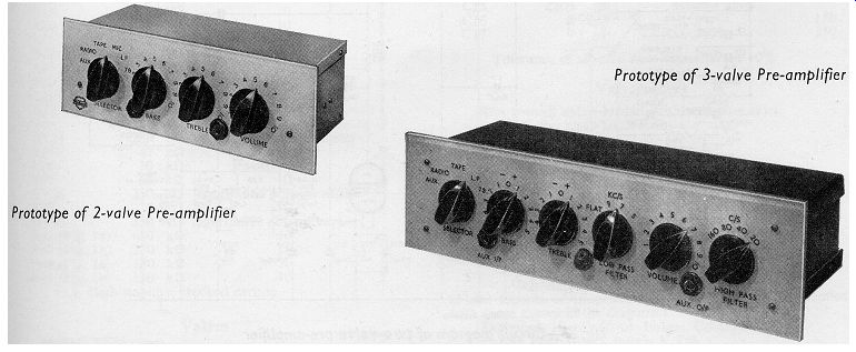
The circuits described in this section have been designed principally for use with amplifiers built to the 20, 10, and 3W circuits discussed in Sections 5, 6 and 7. They can, however, be used with any power amplifier which does not require an input signal greater than 250mV for full output. Input facilities are provided for magnetic and crystal pick-up heads, tape-recorder playback heads, radio tuner units and (in the 2-valve (tube) circuit) a microphone. An auxiliary input position is provided for ancillary equipment such as the tape pre-amplifier circuit described in Section 12.
An additional output position, which is independent of the tone controls, is also provided with both circuits, enabling programs to be taken to a tape amplifier while they are being fed from the normal output position to a power amplifier. Both the auxiliary input and the additional output positions have jack sockets which are situated at the front of the chassis.
All the input sockets in each circuit are connected to one switch which selects one input at a time. In both circuits this switch also short-circuits the unused sockets to earth, an arrangement which considerably reduces the amount of ‘break-through' between channels. The positions of the switch, from left to right, are:
Auxiliary, Radio, Tape, Microphone (in the 2-valve (tube) circuit only)
Microgroove and 78 r.p.m.
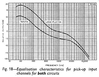
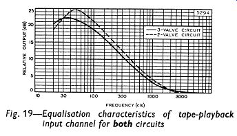
The equalization for disc recordings conforms to the present R.I.A.A. characteristics which have been adopted by most of the major recording companies. The tape-playback characteristic is intended for use with high-impedance heads when replaying prerecorded tapes at a speed of 7 1/2 inches per second.
The tone controls used in both circuits cover a wide range of frequencies and provide boost and cut for high and low frequencies. Switched high- and low-pass filter networks are included in the 3-valve (tube) circuit so that unwanted signals such as rumble and record scratch can be eliminated.
------------
---------- Fig. 1, 2.
Series resistors are used in the input circuits so that the sensitivity and impedance of any channel can be adjusted accurately. The component values given in Figs. 2 and 3 are intended for sources encountered most frequently, but the sensitivity and impedance* of each channel can be altered by changing the value of the appropriate series resistor.
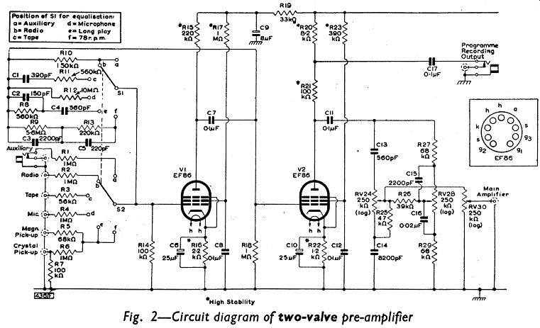
No feedback is used in the second stage of the 2-valve (tube) pre-amplifier.
The full output from the anode of the second EF86 is taken to the passive tone-control network and an auxiliary output is taken from the junction of R20 and R21 to the program-recording jack socket.
*The impedance of the input channels includes the grid impedance of the EF86 modified by the feedback components as well as the impedance of the input network.
CIRCUIT DESCRIPTIONS
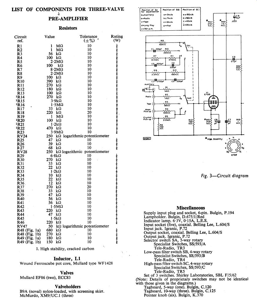
Two Mullard high-gain pentodes, type EF86, are used in the 2-valve circuit of Fig. 2. In the 3-valve circuit shown in Fig. 3, two EF86 and a Mullard double triode, type ECC83, are used.
First Stage of 2- and 3-Valve Circuits
All the equalisation takes place in the first stage of both circuits, and is achieved by means of frequency-selective feedback between the anode and grid of the first EF86. This arrangement has been chosen because the grid-circuit impedance of the first stage should be low. A low impedance at this grid lessens hum pick-up and reduces the effect of plugging-in external low-impedance circuits. Furthermore, the arrangement also results in low gain in the first stage. Hence, Miller effect between the anode and grid of the first EF86, which can be troublesome when high values of resistance are used in series with the grid, is reduced.
Second Stage of 3-valve (tube) Circuit
The second stage of the 3-valve (tube) pre-amplifier circuit of Fig. 3 has a linear frequency-response characteristic and its gain is reduced by a small amount of negative feedback applied at the control grid by way of the resistor R23. The output of this stage is taken from the anode to the tone-control network, and also to the program-recording output socket. Because of the negative feedback, the tone controls have very little effect on the frequency response at this anode.
Third Stage of 3-valve (tube) Circuit
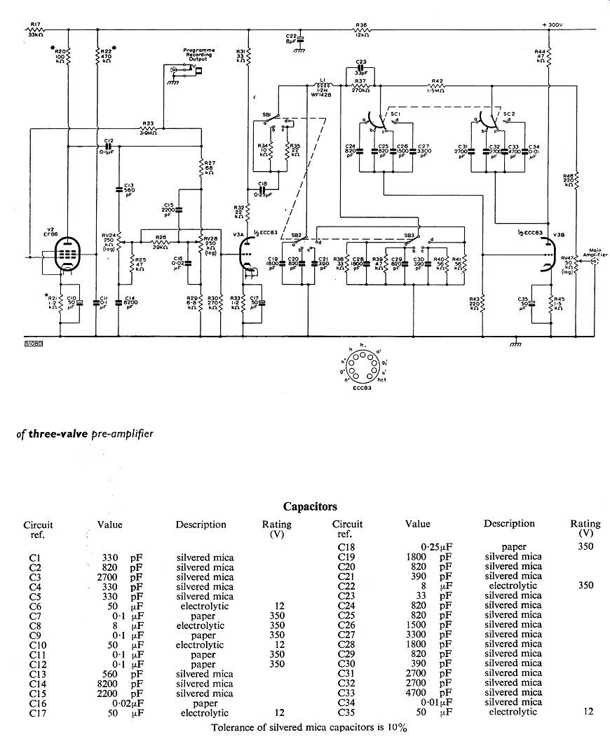
The output stage of the 3-valve (tube) pre-amplifier is made up of the filter circuits. The low-pass filter is situated between the two sections of the ECC83, and is arranged on the switch SB. It incorporates a Mullard wound pot-core inductor, type WF1428, in a p-type network.
The high-pass filter is arranged on the switch SC and consists of two RC networks in a feedback loop around the second triode section of the valve (tube) .
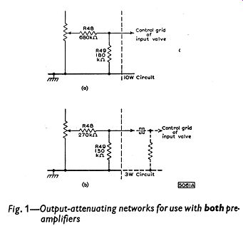
Output Attenuating Networks
The sensitivity and impedance of each channel have been chosen for sources which are likely to be encountered most frequently. The level of output signal from the pre-amplifier will have to be adjusted if it is to be used with power amplifiers having different sensitivities from the 20W circuit. The signal should be attenuated by using a simple potential divider as shown in Fig. 1. The values of resistance in Fig. 1 (a) are for an attenuator suitable for the control-less version of the 10W amplifier (Section 6) and those in Fig. 1 (b) are suitable for the control-less 3W amplifier (Section 7).
------------
H.T. Supplies
The h.t. currents taken by the 2-valve (tube) and 3-valve (tube) pre-amplifiers are respectively 3mA at 230V and 6mA at 250V. The values of the smoothing components for these supplies depend on the combination of preamplifier and power amplifier. Appropriate values are given in Tables 1 and 2. The points from which these supplies are taken are shown in the complete circuit diagrams of Sections 5,6 and 7 for the 20W, 10W and 3W amplifiers.
The l.t. current taken by the 2-valve (tube) pre-amplifier is 0.4A at 6.3V and that required by the 3-valve (tube) circuit is 0.7A at 6.3V.
CONSTRUCTIONAL DETAILS
The chassis design and layout of both pre-amplifiers are intended specifically for the home constructor. Conventional box-type chassis are not used. Instead the chassis are made up on the unit system, the separate parts being joined together during the assembly of the equipment. Both chassis are made up of five separate pieces of 16 s.w.g. aluminum sheet, the dimensions (in inches) of which are as follows:
2-valve (tube) 3-valve (tube) pre-amplifier pre-amplifier
(a) Front panel 9 x 3 12 1/2 x 3 ½
(b) Rear panel 16 x 2 1/2 20 1/ x 2 1/2 2 (c) Mounting strip 8 7/8 x 1 12 5/8 x 1
(d) Cover panel (two) 9 1/8 x 3 1/2 12 5/8 x 4 1/8
The pieces of the chassis should be marked and cut as indicated in Fig. 4 (2-valve (tube) circuit) and Fig. 5 (3-valve (tube) circuit).
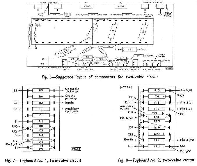
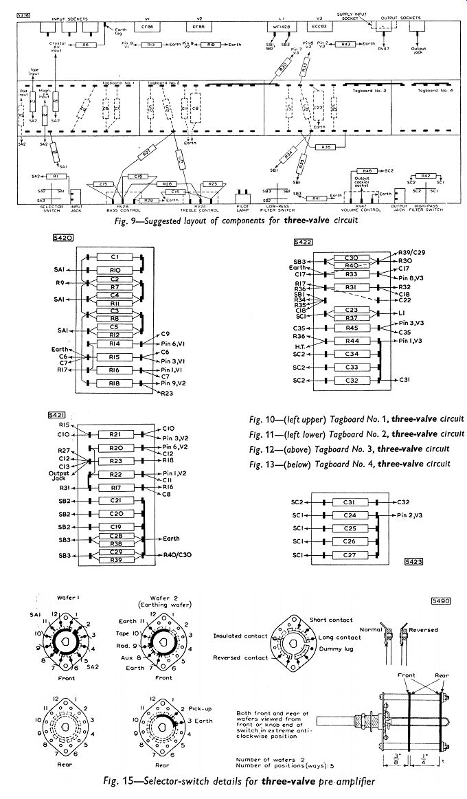
For ease of assembly, components should be mounted on the tagboards, and these should then be bolted to the mounting strip before the strip is attached to the rear plate. Diagrams showing the positions of the components on the tagboards are given in Figs. 7 and 8 for the 2-valve (tube) pre-amplifier, and in Figs. 10, 11, 12 and 13 for the 3-valve (tube) circuit.
When the mounting strip and tagboards have been attached to the rear plate, connections should be made between the valve (tube) holders and components. The valve (tube) holders should be mounted so that the valve (tube) s will be on the outside of the completed chassis and the valve (tube) s should be fitted with screening cans.
--------
------Tbl 1, 2
The potentiometers and switches should be mounted on the front panel of the chassis and the other components which make up the tone-control network should be connected to them. The front panel should then be bolted to the back panel, and the remaining components should be connected in position as indicated in the general layout diagrams of Fig. 6 (2-valve (tube) pre-amplifier) and Fig. 9 (3-valve (tube) pre-amplifier). The series input resistors should be connected directly between the input sockets and the selector switch.
It should be noted that the input-selecting switch for both circuits has a third set of controls not indicated in the circuit diagrams, which short-circuits the unwanted inputs to earth. Details of these switches are shown in Figs. 14 and 15.
Details of the low-pass filter switch SB used in the 3-valve (tube) pre-amplifier are drawn in Fig. 16. The construction of the high-pass filter switch SC is such that the capacitors of the filter are progressively connected in parallel. The wafer arrangement is drawn in Fig. 17. This. arrangement reduces switch clicking and also obviates the need for large capacitors in the network.
The connection to the program-recording output jack on the front panel of the 3-valve (tube) pre-amplifier should. be made with coaxial cable from the junction of R27 and C13. This jack socket and that of the 2 valve (tube) circuit may be connected to a coaxial output socket on the back of the pre-amplifier if it is needed for a fixed recorder.
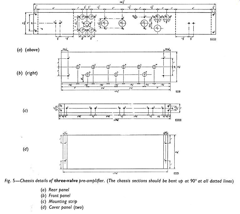
Fig. 5
----------71
-------- Fig. 6-7
------------ Fig. 9-15
--------------
PERFORMANCE
The values for hum and noise in the pre-amplifiers which are quoted below for each input channel have been measured with each of the pre-amplifiers connected to a 20W power amplifier. The measurements were made at the output socket of the power amplifier when the input terminals of the pre-amplifier were open-circuited.
The frequency-response curves were also obtained with these combinations of pre-amplifier and power amplifier.
The sensitivity figures given below provide full outputs from both pre-amplifiers. Total harmonic distortion in the two-valve (tube) pre-amplifier is less than 0.15 % at the rated output level and is only 0.24% at ten times this output. Total harmonic distortion in the 3-valve (tube) pre-amplifier is less than 0.1% at the rated output and only 0.65% at ten times the rated output. A rapid increase in distortion does not occur until the pre-amplifiers are considerably overloaded.
PICK-UP INPUT CHANNELS
Equalization curves for the magnetic and the crystal pick-up input channels in both pre-amplifiers are drawn in Fig. 18. The difference in sensitivities (indicated in this figure) between the positions for microgroove and 78 r.p.m. records is achieved with the different basic levels of feedback provided at the respective positions of the selector switch. The change is necessary because standard discs are recorded at a higher level than microgroove discs.
Magnetic Pick-up Position
2-valve (tube) 3-valve (tube) pre-amplifier pre-amplifier
Input Impedance 100 k-o 100 k-o
Sensitivity at 1 KHz
(a) microgroove 4.8mV 7mV
(b) 78 r.p.m. 13mV 12mV Hum and Noise (below 20W)
(a) micro-groove 55dB 53dB
(b) 78 r.p.m. 57dB 58dB
This channel is most suitable for pick-up heads of the variable-reluctance type, but moving-coil types which have higher outputs can be used if a larger value of series resistance is included.
Crystal Pick-up Position
2-valve (tube) 3-valve (tube) pre-amplifier pre- amplifier Input Impedance 100k-o100k-o
Sensitivity at 1 KHz
(a) Microgroove 70mV 150mV
(b) 78 r.p.m. 210mV 270mV Hum and Noise (below 20W)
(a) microgroove 55dB 53dB
(b) 78 r.p.m. 57dB 58dB
Low- and medium-output crystal pick-up heads can be used for this channel. The input is loaded with the 100k-oresistor (causing bass loss) in order that its characteristic shall approximate to that of a magnetic cartridge, and to allow the same feedback network to be used. This produces the best compromise with most types of pick-up head.
However, if the head is not suitable for this form of loading, or if its output is too high, then it can be connected to the auxiliary input socket, which is discussed fully below. With this channel, the pick-up output is fed into a 1M-O load which compensates automatically for the recording characteristic.
TAPE PLAYBACK INPUT CHANNEL
2-valve (tube) 3-valve (tube) pre-amplifier pre-amplifier
Input Impedance 80k-o (approx) 80k-o (approx)
Sensitivity at 5KHz 4mV 2.5mV
Hum and Noise (below 20W) 52dB 47dB
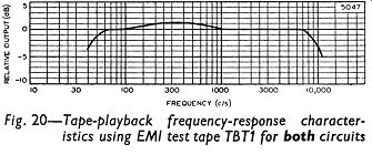
The tape equalization characteristic used in each pre-amplifier is shown in Fig. 19. Each channel is intended for replaying pre-recorded tapes using high-impedance heads, and the characteristics adopted result in good performance with these heads. The frequency-response curve for playback with EMI test tape TBT1 is drawn in Fig. 20. If a greater sensitivity is required, the value of the series input resistor can be decreased until the desired sensitivity is obtained.
--------- Fig. 18-21
MICROPHONE INPUT CHANNEL (two-valve (tube) circuit only)
Input Impedance 1 M-o
Sensitivity 7.5mV
Hum and Noise (below 20W) 44dB
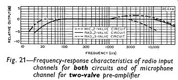
The frequency-response characteristic for this channel is given in Fig. 21. The microphone input channel is intended for use with high-impedance systems such as crystal microphones or magnetic microphones with transformers.
RADIO INPUT CHANNEL
2-valve (tube) 3-valve (tube) pre-amplifier preamplifier
Input Impedance 1 M-O
1 M-O
Sensitivity 330mV
250mV Hum and Noise (below 20W) 63dB
63dB
The frequency-response characteristics of both preamplifiers are given in Fig. 21. With the values of impedance and sensitivity quoted above, this channel should meet most requirements. Other values can easily be obtained, however, by altering the feedback resistor and the series input resistor. If the input impedance of the channel is too high, it can be reduced by connecting a resistor of the appropriate value between the input end of the series resistor and the chassis.
AUXILIARY INPUT CHANNEL
It can be seen from the circuits that the auxiliary channel is identical with the radio input channel in both pre-amplifiers. The channels can therefore be used for high-output crystal pick-ups, for example, or for a tape pre-amplifier such as that described in Section 12. If it is desired to use a microphone with the 3-valve (tube) circuit, a separate microphone preamplifier or an input-mixing pre-amplifier can be connected to the auxiliary socket. The auxiliary input is taken to a jack socket at the front of the chassis. This makes it easier to connect a portable tape recorder. The jack-socket termination of the auxiliary input position is such that insertion of the jack disconnects the coaxial socket on the rear panel.
TONE CONTROLS
The treble and bass tone-control characteristics of the pre-amplifiers are shown in Figs. 22 and 23. These indicate that an adequate measure of control is provided in both units for most applications.
Low-impedance controls have been adopted in the 2-valve (tube) circuit so that any capacitance resulting from the use of long coaxial leads between the preamplifier and main amplifier will have a minimum effect on the output impedance of the pre-amplifier.
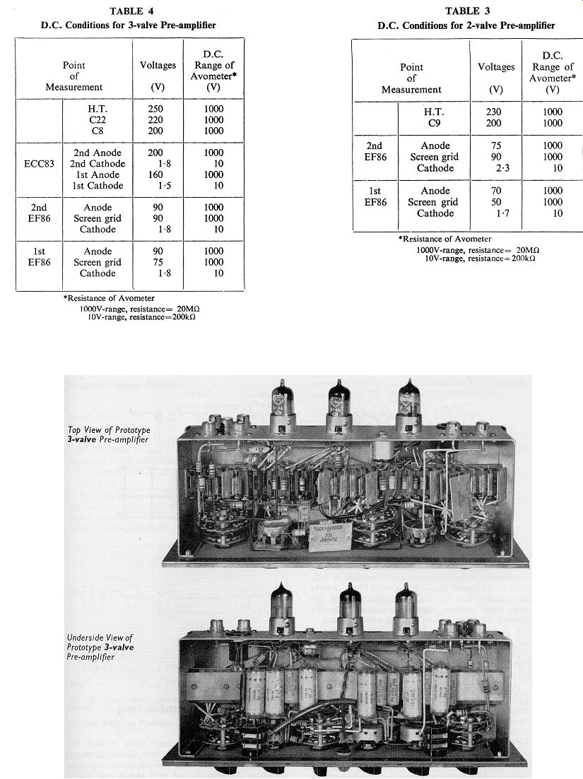
D.C. CONDITIONS
The d.c. voltages at points in the equipment should be tested with reference to Table 3 for the 2-valve (tube) circuit and to Table 4 for the 3-valve (tube) circuit. The results shown in these tables were obtained using an Avometer No. 8
AUXILIARY OUTPUT POSITION
The output from the second EF86 of both circuits is available at this auxiliary position enabling a record of program material to be made with tape equipment. This additional output is taken to a jack socket at the front of the chassis. Excellent recordings can be made even when the input signal is derived from a low-output magnetic pick-up.
An output of about 250mV is available at this socket, and the impedance is low. Recording equipment plugged into this socket should not have an input impedance less than 500k-o. The tone controls and the filter networks are inoperative when this output is used.
-------------
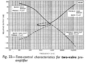
Fig. 22-24
FILTER NETWORKS (three-valve (tube) circuit only)
The characteristic of the low-pass filter has a slope of approximately 20dB per octave. The components of the network are arranged for operation at 5, 7 and 9KHz in positions (a), (b) and (c) respectively of the switch SB in Fig. 3. Position (d) of the switch gives a flat characteristic.
The characteristic of the high-pass filter has a slope of approximately 12dB per octave. Operation is at 160, 80 and 40Hz respectively at positions (a), (b) and (c) of the switch SC. Position (d) of the switch cuts at 20Hz: this is considered preferable to allowing the response to continue to lower frequencies because of the possibility of the amplifier or loudspeaker being overloaded.
-------------
Tbl 4-5