A thyratron differs from a vacuum triode in that it is filled with an easily-ionized gas, rather than being evacuated. Under certain conditions the gas will become ionized, when grid and plate voltages are applied, and permit a very heavy electron current to flow between cathode and plate.
An important characteristic of the thyratron is the inability of its control grid to cut off the plate current-once a thyratron begins to conduct, the only way it can be cut off is for the plate voltage to be lowered almost to zero-15 or 20 volts is not abnormally low.
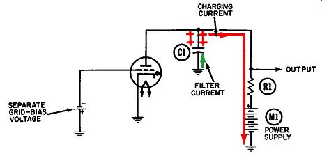
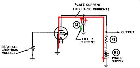
The schematic symbol is the same for a vacuum tube or thyratron except for a dot within the tube envelope, as shown for the thyratron in Figs. 1 and 2.
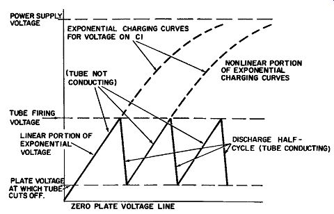
Thyratrons are capable of generating sawtooth-voltage wave forms (so named because of their shape) which are used for sweeping the electron beam across the face of a cathode-ray tube in an oscilloscope, radar set, or other application where it is desired to gradually move the beam across the face of the tube and then quickly return it to the starting point. Fig. 3 shows the waveform generated at the plate.
The only significant current in this circuit crosses from cathode to plate and could perhaps be called "plate current." However, its movement during the conducting and nonconducting period of each cycle is quite different from the plate-current flow in a vacuum tube. Let us start at the beginning, when the power supply is turned on and applies a positive voltage to the plate.
In order for the plate voltage to rise from zero to the power supply voltage, free electrons must be drawn away from the plate of the tube, the upper plate of capacitor C1, and from any component connected to the output. This is the charging process and the amount of time it takes depends on the values of plate load resistor R1 and capacitor C1 in Fig. 1. R1 is very large, several hundred thousand ohms; and C1 is 1,000 micro-micro farads or so. The plate-voltage curve begins at zero and rises exponentially toward the power-supply voltage, as shown in Fig. 3. (An exponential curve is one which does not rise or fall at the same rate from left to right.) The dashed-line portions of the curves in Fig. 3 represent the voltage which would exist at the plate if the charging process were completed.

Fig. 1. Operation of the thyratron sawtooth-voltage generator-charging
half-cycle. In a thyratron tube, the value of plate voltage at which the gas "breaks
down" or becomes ionized is called the firing voltage.
When this happens, the molecules of gas becomes ionized and release their free electrons, and the interior of the tube becomes filled with both positive ions and negative electrons. Attracted by the positive voltage at the plate, the negative electrons flow there in a steady stream and are replaced by other free electrons emitted by the heated cathode.
The value of the firing voltage depends partly on the applied grid-bias voltage, shown as a separate battery in Figs. 1 and 2. In a typical thyratron tube, this grid bias is on the order of -5 volts, and the firing voltage at the plate is 75 to 100 volts.
Once the tube begins to conduct, it delivers electrons to the plate much faster than high-value plate-load resistor R1 can pass them. The electrons accumulate on the upper plate of capacitor C1 and reduce its charge to a very low positive voltage, as depicted in Fig. 2. The charged capacitor is now said to be "discharging through the tube." Strictly speaking, the capacitor is not discharging through the tube, but its positive voltage is being discharged because the tube supplies a large number of free electrons (in the form of plate current) to the capacitor.
This discharging process occurs in only a tiny fraction of the time required for the charging process, as shown by Fig. 3.
Once the gas has been ionized, the grid can no longer control the flow of current. Now it can only be stopped by reducing the plate voltage to a very low value-on the order of 15 or 20 volts. This might be called the "cutoff" voltage for a thyratron.

Fig.
2. Operation of the thyratron sawtooth-voltage generator-discharging half-cycle.

Fig. 3. Sawtooth output voltage generated at plate of thyratron generator.
The exponential charging curve is almost a straight line in the low plate-voltage
regions, between the cutoff and firing voltages.
This area, referred to as the linear portion of the curve, is where the sawtooth voltage is generated.
As in any tube, the current must have a closed path leading back to the cathode. In Figs. 1 and 2, the complete path is from cathode to plate, through the load resistor and power supply to ground, and back to the cathode.
The much shorter discharge half-cycle makes the thyratron an ideal sweep generator. After the beam has been swept across the face of the screen, it must be retraced as quickly as possible or the viewer will see a flickering picture. The short discharge period is normally used for retrace, so that the beam will be out of action as briefly as possible.
A filter current, shown in green, flows between the lower plate of capacitor C1 and ground. In Fig. 1 the current flows upward because of normal capacitor response to the voltage changes at the plate of the tube, but is driven downward in Fig. 2 by the plate-current electrons flowing onto the upper plate.
Obviously, a high positive value of plate-supply voltage con tributes to greater linearity of the charging half-cycle, whereas a lowered value would lead to greater curvature in the discharge curve.