SECTION 1: INTRODUCTION
Classification of Oscillators-Electron Flow-Conductors and Resistors-Capacitance-Capacitor Construction-Capacitive Reactance-Inductance - Inductor Construction - Inductance-Capacitance Combination-Magnetic Lines of Force-Resistor-Capacitor Combination-Time Constants-Coulomb's Law-Ohm's Law.
SECTION 2: CRYSTAL OSCILLATOR
Piezoelectric Effect-Crystal Construction-Crystal-Oscillator Circuit-Feedback-Current Paths-Biasing-Time Constants--voltage Storage-Phase Relationships-Frequency Determination.
SECTION 3: THE HARTLEY OSCILLATOR
Feedback-Oscillating Tank Current-Circuit Operation-Auto transformer Action-Feedback Current-Operating Frequency.
SECTION 4: THE COLPITTS OSCILLATOR
Circuit Operation - Current Paths-Radio Frequency Chokes - Feedback Current-Biasing-Time Constants-Grid Loading Drive Voltage.
SECTION 5: THE TUNED-PLATE-TUNED-GRID OSCILLATOR
Tank Currents-Feedback Current-Grid-Leak Action-Decoupling-Tuning the Tank Circuits-Phase Relationships.
SECTION 6: THE ELECTRON-COUPLED OSCILLATOR
The Grid Tank-Current Paths-Feedback-Isolation Between Plate and Grid-Frequency Stability-Screen-Grid Circuit-voltage Dividers-Circuit Stability.
SECTION 7: PHASE-SHIFT OSCILLATOR
Circuit Operation-Current Paths-Phase-Shifting Networks Frequency Determination-Phase Relationships-Screen-Grid Circuit-Filter Currents.
SECTION 8: BLOCKING OSCILLATORS
Circuit Operation-Transformer Action-Conducting and Non-conducting Periods-Frequency Control-Synchronization-Output Coupling.
SECTION 9: Multivibrators
Free-Running Multivibrator-Coupling Capacitors-Time Constants-Circuit Operation-Eccles-Jordan Multivibrator-Biasing Triggering.
SECTION 10: THYRATRON SAWTOOTH GENERATORS
Thyratron Principles-Charging Process-Firing Voltage-Discharging Process-Charge and Discharge Curves.

A dynamic new approach to the explanation of electronic circuit action, utilizing
unique four-color diagrams to help you visualize what takes place inside oscillator
circuits. Includes circuit fundamentals, plus an analysis of the nine basic
oscillator circuits.
Intro
The objective of this guide, and of the subsequent volumes in this series, is to provide an understanding of how standard electronic circuits operate. Fundamentally, there are only a few basic actions involving electrons. And although these actions occur over and over in all circuits, each has acquired a multiplicity of names, which are not usually descriptive of action but of application.
This nonconformity of names and terminology for electronic actions is a formidable barrier to the study of electronics.
Like many that have gone before it, this guide is represented as a "nonmathematical" treatment. However, much of the terminology of electronics is of necessity mathematical and quite abstract. Thus, the omission of complex formulas in a text does not make it "nonmathematical" if it still contains words and phrases understandable only to those having the necessary mathematical background. It is practically impossible to write a guide on electronics without using many such words and phrases, but in every instance the terms used in this guide have been clarified through the use of illustrations which portray all identifiable currents and voltages in a somewhat unique manner.
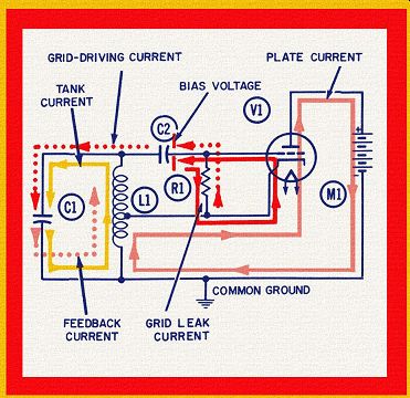
Multiple colors are used to show what takes place during successive half-cycles (or successive quarter-cycles) during the operation of each circuit under consideration. Every electron cur rent is identified and discussed in detail, so that you can easily follow its path through all parts of the circuit. Frequently, more than one current will flow simultaneously through a component.
An engineer or mathematician may rightly be interested in the total current through such a component, and would arrive at this figure mathematically. On the other hand, the student aspiring to become a technician or engineer must know more than the exact amount of total current or voltage; he must also be able to "visualize" each of the significant currents and voltages in order to learn how one affects the other. This ability to visualize what is happening inside a circuit can be accomplished by almost anyone, even without a mathematical background.
Electron currents in the various circuits have been treated much like "moving parts" of a machine. If we wanted to know how a piece of machinery worked, the simplest way would be to observe a cutaway model as it goes through several cycles of operation. Through the use of the illustrations in this guide, we can "look inside" the individual components, and "see" what is happening. Thus, the circuit diagrams used herein are more than just abstract drawings of circuit connections--they are concrete "working models" of circuit actions in diagram form.
It is our hope that this series of texts will find acceptance at each of the three important educational levels now concerned with the teaching of electronics--high schools, technical and vocational schools, and undergraduate levels in college engineering.
The material is neither too advanced for high schools, nor too elementary for colleges. Students at any of these educational levels have one great desire in common--to achieve an early understanding of how circuits operate. The ability of an electronics student to visualize what is happening inside electrical components is an essential building block for later studies directed either toward design engineering, or toward maintenance, repair, and usage of electronic equipment.
The guide is recommended especially for engineering students in fields other than electronics. Because electronics is utilized in many fields, engineers of all categories should have a basic under standing of electronic circuit actions and applications. This series of guides is intended to convey such an understanding.
Finally, the guide is respectfully recommended to executives in industry. In myriad ways, management is becoming more and more involved with electronics·. A greater understanding of its basic principles-without the necessity for an intense study of electronics engineering-will be of inestimable value to persons at the managerial level.
The writer is indebted to many individuals in the educational field for their guidance and help in reviewing some of the original drawings for this series.
Also see: Guide to Vacuum Tube Amplifier Circuits