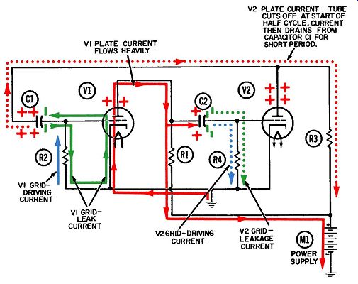
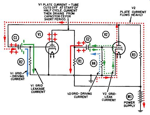
The multivibrator circuit is widely used for providing the timing function in television, computers, radar, and many other applications. The basic free-running multivibrator circuit is given in Figs. 1 and 2. Its components are:
R1-Plate-load resistor (about 20,000 ohms) for V1.
R2-Grid-biasing and -driving resistor (about 2 megohms) for V1.
R3-Plate-load resistor (about 20,000 ohms) for V2.
R4-Grid-biasing and -driving resistor (about 1 megohm)
for V2.
C1-Grid coupling and blocking capacitor (800 micro-micro-farads) for V1.
C2-Grid coupling and blocking capacitor ( also 800 micro microfarads) for V2.
V1 and V2-Triode amplifier tubes.
M1-Power supply.
There are six currents at work in this circuit, and their movements must be understood in order to comprehend how the circuit operates as a whole. Each of the current paths is shown in a different color in Figs. 1 and 2. These currents, and the colors representing them, are:
1. Plate current for V1 (solid red).
2. Grid-leak biasing current for V1 (solid green).
3. Grid-driving current for V1 (solid blue).
4. Plate current for V2 ( dotted red).
5. Grid-leak biasing current for V2 ( dotted green).
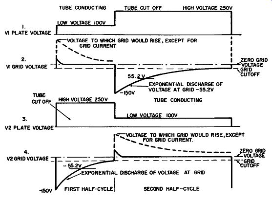
6. Grid-driving current for V2 ( dotted blue) . The voltage waveforms resulting from the current flow at the plate and grid of each tube are given in Fig. 3.
CIRCUIT DESCRIPTION
As mentioned previously, the circuit in Figs. 1 and 2 is connected to operate as a free-running multivibrator. Its pulse repetition frequency is determined by the values of the resistors and capacitors, and by the conduction characteristics of the two vacuum tubes.

Fig. 1. Operation of free-running
multivibrator-first half-cycle.

Fig. 2. Operation of free-running multivibrator--second half-cycle. Operation
begins when plate voltage is applied to V1 and V2 simultaneously. As each tube
conducts electrons from cathode to plate, the voltage at each plate will drop-but
not by the same amount. If both tubes conducted exactly the same number of
plate-current electrons (which they never do) and if the two plate-load resistors
were exactly the same value (which they never are) , then both would be identical.
But such an assumption is purely hypothetical-the two drops will never be the
same.
Let us assume that V1 conducts the greater amount of plate current. As a result, its plate voltage will drop to a lower positive value than V2's. Let us also assume that it drops to + 100 volts, and that the supply voltage is +250 volts. It is true to say that capacitors oppose any change in voltage, or another way of saying the same thing: "it is impossible to instantaneously change the voltage across a capacitor." The fundamental meaning of these statements will be made clearer by now observing the action within capacitor C2. Before tube V1 conducts, the voltage on the left plate of C2 ( and also on the plate of V1) is the +250 volts from the power supply, while the voltage on the right plate is essentially zero since it is connected to ground through grid resistor R4. Thus, the moment before conduction begins, the voltage across the two plates of the capacitor is +250 volts.
We know that the voltage across C2 does not change at the same instant the tube conducts and the plate voltage drops. It will remain at +250 volts momentarily, and then decrease to + 100 volts as the electrons flow onto the left plate of C2. As they do, an equal number will flow from the right plate and downward through R4. This grid-driving current, shown in dotted blue in Fig. 1, produces a voltage drop across R4. Now the voltage at the junction of R4 and C2 (hence, the grid voltage) is -150 volts.
Line 4 of Fig. 3 shows the voltage waveform at the grid of tube V2. At the start of the first half-cycle this voltage suddenly goes from zero to -150 volts, and then returns toward zero at an exponential rate determined by a corresponding exponential decay in the grid-leak current (shown in dotted green) flowing downward through R4 to ground.
The sudden drop immediately cuts off the plate current through V2 and thus allows its plate voltage to rise toward the value of the supply voltage. It will stay at 250 volts until the grid voltage has gone from -150 volts to the cutoff value of -10 volts. The first half-cycle has now ended.
The second half-cycle begins when the rise in plate current through tube V2 causes a drop in its plate voltage, similar to the action in tube V1. Since plate-load resistors R1 and R3 are both equal in value, the voltage at the plate of V2 drops from +250 to + 100 volts, just as the plate of V1 did.
Capacitor C1 starts this second half-cycle with 250 volts across it, since its one plate is connected to the plate of tube V2 and its other plate is connected to ground through grid resistor R2.
C1 will also oppose any change in voltage across its plates. The voltage on the right plate, which is also the voltage applied to the grid of tube V1, immediately goes from zero to -150 volts as current flows downward through grid resistor R2. This current decays exponentially to zero, and the resultant voltage across it (which is also the voltage applied to the grid of tube V1) will likewise decay toward zero at the same exponential rate, as shown in Fig. 3. It is important to note why the second half-cycle is so much longer than the first. You will recall that C1 and C2 have equal values of 800 micromicrofarads; but R2 is 2 megohms, or twice the value of R4. Using the formula (T =RX C) explained earlier, we can calculate the time constant for the C1-R2 combination as follows: We know:
R = 2 megohms = 2 X 10¹¹ ohms, C = 800 micro-microfarads = 800 X 10-12 farads, T=RxC. Therefore, T = 2 X 10^6 X 800 X 10^-12=2 X 800 X 10^-6= 1,600 X 10^-6 seconds = 1,600 microseconds Similarly for C2-R4, where the only new value is R4 which is 1 megohm (1 X 10'; ohms), the time constant is: T= 1 X 10^11 X 800 X 10^-12 = 800 X 10^-6 seconds = 800 microseconds
Thus, the time constant of C1-R2 in the grid circuit of V1 is twice as long as the one for C2-R4 in the grid circuit of V2.

Fig. 3. Grid- and plate-voltage waveforms for free-running multivibrator.
Remember that the time constant of an R-C circuit is the length of time it
will take the capacitor to discharge to 63.2% of its original value. Therefore,
during the first 800 microseconds after the first half-cycle starts, the grid
voltage on V2 will discharge to about -55.2 volts, or 36.8% of its original
-150 volts. This is shown in line 4 of Fig. 3.
After three time periods of 800 microseconds each, the grid of V2 will have discharged to about -7.5 volts. Since its cutoff value is -10 volts, V2 will start conducting before the third time period is completed, ending the first half-cycle and starting the second one.
Now the grid of V1 will also discharge to -7.5 volts after three time periods of 1,600 microseconds each. Slightly before the end of the third time period, V1 begins conducting and the first half cycle starts all over.
Thus, we see that the first half-cycle is slightly less than 3 X 800 microseconds, or 2,400 microseconds; and that the second half cycle is twice as long, or not quite 4,800 microseconds.

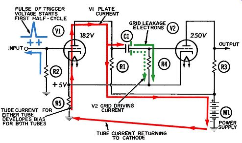
Fig. 4. Operation of a modified Eccles-Jordan multivibrator-first half cycle.
The waveforms at the plates of V1 and V2 will be rectangular, as shown by lines
1 and 3 of Fig. 3, because of the unequal half-cycles. If the two half-cycles
were equal-that is, if R2 and R4 had identical resistances-the waveforms would
be square, and the multivibrator could then be considered a crude form of square-wave
generator. (Actually, they would only be approximations of square waves. However,
the term square wave is adequate for conveying a general understanding of how
the circuit operates.) Note in lines 2 and 4 of Fig. 3 that the grid voltage
rises exponentially until it reaches -10 volts {its cutoff value). At this
point, it almost immediately jumps to a slightly positive value, then drops
back to the zero-voltage line and hovers there during the remainder of the
half-cycle that the tube is conducting.
What prevented the grid from being driven positive instead of remaining at (or near) zero? Whenever the control grid is driven positive (as it was here), it will attract electrons from the plate current. These grid-leak electrons, sometimes more loosely described as "grid current," collect on the control grid and drive the positive-going grid voltage back to zero.
The dotted portions of lines 2 and 4 in Fig. 3 show how high the grid voltage would rise, were it not for the grid-leak current.
At the start of the first half-cycle (Fig. 1), for example, the current through V2 is suddenly cut off, and the voltage at the plate rockets from + 100 volts toward the supply voltage of +250 volts. Capacitor C1, connected to the plate of V2, opposes this sudden change in voltage across its plates-it tries to drag the VI grid 150 volts in the positive direction, from -10 volts to + 140 volts, but is prevented from doing so by the grid-leak current flowing out of VI and onto the left plate.
A series of similar events also occurs at the start of the second half-cycle (Fig. 2) and prevents the V2 grid voltage from rising any further after it passes the zero-voltage point.
During the first half-cycle, the grid-leak and -driving currents flowing through R2 travel in opposite directions. The driving current predominates and "triggers" V1 to start the first half cycle. Through R4, however, the two currents flow in the same direction. (Remember that grid-leakage electrons always flow downward, in an attempt to discharge from their storage points on the grid sides of the grid capacitors.) Fig. 5. Operation of a modified Eccles-Jordan multivibrator-second half cycle. In Fig. 2 the situation has been reversed-the currents flow in the same direction through R2, but in opposite directions through R4. The driving current is more temporary than the leakage current, since it flows only while the plate voltage in the other tube is rising or falling.
Summary
Both multivibrator tubes will begin to conduct plate current when the supply voltage is applied. One of the tubes inevitably will conduct slightly more current, even though the two circuits are identical. When this happens, its plate voltage will fall and, by capacitive coupling, reduce the voltage at the grid of the second tube.
The lower voltage will reduce the current through the second tube and raise its plate voltage. This rise is capacitively coupled to the grid of the first tube, increasing the plate current and reducing the plate voltage of the first tube still further. The effects are cumulative, so that the first tube conducts more and more heavily until it cuts off the second tube.
The grid voltage of the second tube will have been driven considerably below cutoff during this sequence; and because of the grid-leakage electrons it has accumulated, the second tube re quires considerable time to discharge this negative voltage to ground before it can conduct again.
When this does happen, the earlier sequence is repeated, only this time in reverse. The plate voltage of the second tube begins to drop because of the rising plate current. Since the plate is capacitively coupled to the grid of the first tube, its voltage drops accordingly, reducing the plate current and raising the plate voltage of the first tube. By capacitive coupling the grid voltage of the second tube is raised still higher, and so on, in another cumulative series of events. The first tube will soon be cut off, and will remain off until its negative grid voltage can again discharge to the cutoff value.
Shifting conduction from one tube to the other in this manner, the multivibrator circuit will oscillate indefinitely. For this reason it has been aptly named a "flip-flop" circuit. Fig. 6. Voltage waveforms during one cycle of operation of the Eccles Jordan multivibrator.
THE ECCLES-JORDAN MULTIVIBRATOR
The modified Eccles-Jordan multivibrator (Figs. 4 and 5) is also known as a "one-shot" or "trigger" multivibrator. Unlike in the free-running multivibrator described previously, only one of the tubes has its plate coupled back to the grid of the other.
This feature prevents the circuit from cycling repeatedly. Also, both tubes use a common cathode-biasing resistor to drive the voltage at both cathodes in the positive direction, in a manner which will be explained later. The grid of V1 is returned to ground, whereas in V2 it is returned to the cathode. Since ground is at a lower voltage than the cathodes, normally V1 remains cut off and V2 conducts. The components of this circuit include:
R1-Plate-load resistor (about 20,000 ohms) for V1.
R2-Grid driving resistor for V1.
R3-Plate-load resistor (about 20,000 ohms) for V2.
R4-Grid blocking and driving resistor (about 1 megohm) for V2.
RS-Common cathode-biasing resistor (about 1,000 ohms) for V1 and V2.
C1-grid coupling and blocking capacitor (about 800 micro microfarads) for V2.
V1 and V2--Triode amplifier tubes.
The currents at work in this circuit appear in the following colors in Figs. 4 and 5:
1. Grid driving current for V1 (blue, in Fig. 4.)
2. Plate current for V1 (solid red, Fig. 4).
3. Grid driving current for V2 ( dotted green, in Fig. 4).
4. Plate current for V2 ( dotted red, in Fig. 5) .
5. Grid-leak current (solid green, in Figs. 4 and 5).
The first half-cycle begins with the arrival of a positive triggering pulse at the control grid of V1. This pulse, shown in blue in Fig. 4, draws a small electron current upward through grid resistor R2 and into whatever coupling device is at the left of V1.
V1 is normally cut off (nonconducting) because its grid is connected to ground and thus is at zero voltage, whereas its cathode is at the positive voltage produced by the current flowing upward through cathode biasing resistor R5. On the other hand, V2 normally conducts a substantial amount of plate current.
Plate current for either tube will flow upward through resistor RS. Since both tube cathodes are connected to the top of R5, the two will always have the same positive voltage on the cathode, irrespective of which tube is conducting. Let us assume it is + 11 volts.
Tube V1 is normally cut off because its control grid is connected to ground, or zero voltage, through resistor R2. Hence, the grid is at zero volts also, and we said earlier that the cathodes are at + 11 volts. This leads us into bias, an often misused term.
Bias, in the correct sense, refers to the difference in voltage between the grid and cathode. In this circuit we would normally say the cathode is 11 volts more positive than the grid. But it would be Just as correct to say the grid is 11 volts more negative than the cathode. This 11-volt difference in voltage between the grid and cathode is the bias. (If the cathode were at zero volts instead and the grid were at -11 volts, the bias would still be the same -11 volts.) If we assume that the grid cutoff voltage is -10 volts, V1 will remain cut off as long as its bias is -11 volts. Nothing happens until a trigger pulse exceeding + 1 volt arrives at the grid and raises its voltage above the cutoff value. When the pulse arrives, plate current begins to flow through V1, marking the beginning of the first half-cycle (Fig. 4). Now the V1 plate voltage begins to fall. This drop in voltage is coupled from the plate of V1, via C1, to the grid of V2. The flow of plate current through V2 is cut off, causing the plate voltage to rise rapidly toward the value of the supply voltage.
Unlike in the free-running multivibrator discussed previously, this rise in plate voltage is not coupled back to the grid of V2.
Consequently, the grid voltage of V1 will not rise as high, and V1 will conduct less plate current, than it would if connected as a free-running multivibrator.
This reduction in plate current through V1 (compared with that which would flow in the free-running multivibrator) has two important effects. First, the plate voltage of V1--and hence the voltage at the grid of V2-will not be reduced to as low a value. Secondly, the cathode-bias voltage developed across R5 will be lower during the first half-cycle. Line 3 of Fig. 6 shows this reduction in cathode voltage.
Let us assume the cathode voltage across R5 drops from + 11 volts during the second half-cycle to +5 volts during the first one.
This has the effect of reducing the total grid bias from -11 to -5 volts.
Line 4 of Fig. 6 is essentially an inversion of Line 3; it shows the actual bias on V1. Once the trigger voltage has started this tube conducting, the grid returns fairly quickly to zero volts and the bias stabilizes at -5 volts-enough to permit a reasonable amount of plate current to flow.
Line 5 of Fig. 6 shows the plate-voltage waveform for tube V2.
At the start of the first half-cycle when the plate current is cut off, the plate voltage rises to the value of the supply voltage, and remains there until the plate current is turned on again at the start of the second half-cycle.
Line 6 of Fig. 6 is quite similar to the grid-voltage discharge curves shown in Fig. 3 for the free-running multivibrator, and will therefore not be reanalyzed in detail here. Tube V2 will remain cut off as long as the difference in voltage between its grid and cathode is greater than the cutoff value of -10 volts.
The discharging of capacitor C1 consists of grid-leakage electrons flowing downward through grid resistor R4. The rate of flow, which decreases exponentially, determines the voltage developed across R4.
The first half-cycle ends when V2 begins to conduct. This cuts off the flow of plate current through V1, but in a different manner than in the free-running multivibrator. The increase in total current through cathode resistor R5 raises the voltage at both cathodes, immediately restricting the flow of plate current through V1. As a result, the plate voltage of V1 begins to rise.
This increase is coupled via C1 to the grid of V2, raising the grid voltage and hence the plate current of this tube still further.
This increase in V2 plate current, flowing through common cathode resistor R5, further reduces the plate current through V1, cutting the tube off very quickly.
The second half-cycle, once begun, will continue indefinitely unless retriggered by an outside voltage source. Thus, it will usually last longer than the first half-cycle. The grid voltage of V2 will rise momentarily to a slightly more positive value than the cathode, but will then begin to acquire some grid-leak electrons from the tube, preventing it from rising any further.
Throughout the second half-cycle, the two voltages will remain close to the same value.
The different amount of plate current through each tube is reflected by the waveform voltages at the two plates. When not conducting, each tube plate will rise to the +250-volt supply voltage. However, since V2 conducts more than twice as much current as V1, and since R1 and R3 are equal in value, it follows from Ohm's law that the resulting voltage drop across R3 will be more than twice the one across R1. Consequently, approximately 182 volts has been indicated at the plate of V1 during the first half-cycle, as opposed to 100 volts for V2 during the second half-cycle.