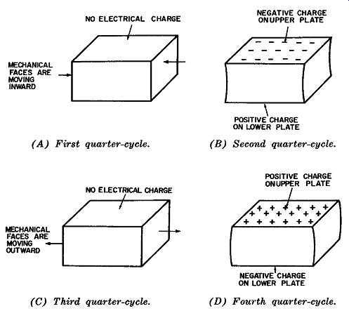
The crystal-controlled oscillator depends on the piezoelectric effect of certain crystals for their ability to generate electric oscillations at radio frequencies. The piezoelectric effect can be visualized from Fig. 1. One peculiar quality of such a crystal is its ability to oscillate structurally as well as electrically. Like all oscillations, this one must be sustained by adding energy from an outside source or it will die out. Using Fig. 1 we will discuss the condition of the crystal during four successive quarter-cycles of an oscillation.
CRYSTALS
Fig. 1A shows the normal physical configuration of a typical crystal. Crystals have various shapes, a flat rectangular plate being the most common. The upper and lower plates are the electrical ones, and the right and left plates the mechanical ones.
When a crystal is oscillating, positive and negative electric charges will alternate between the two electric faces, and mechanical distortion will be evident on the two mechanical faces.
Fig. 1B shows the concentration of a negative charge on the upper plate of the crystal. Although not shown, positive ions are concentrated on the bottom plate. Fig. 1D shows the electrical conditions of the crystal a half-cycle later, when the positive charge is concentrated on the upper plate and the negative charge on the lower one.
Fig. 1B also shows the mechanical distortion of the crystal. Here the right and left plates are drawn inward, while in Fig. 1D they are expanded.
The arrows in Figs. 1A and 1C point in the direction these two plates are moving at the end of the first and third quarter cycles.

Fig. 1. Piezoelectric
effect on a typical crystal for one cycle of operation. ( A) First quarter-cycle.
(B) Second quarter-cycle. (C) Third quarter-cycle. (D) Fourth quarter-cycle.
The thickness of the crystal, the type of material it is cut from, and the orientation of the cut to the crystal material, all have a direct bearing on the frequency at which the crystal will oscillate. A typical quartz crystal, oscillating in the region of 500 kilocycles per second (near the low end of the broadcast band), might have the following approximate dimensions:
Thickness-0.25 inch
Width-1.3 inches
Length-1.0 inch
This describes a crystal about one inch square and one-fourth inch thick.
The type of material used and the orientation of the cut to the original axis of the crystal material are of major significance to the crystal grinder and circuit designer, but not to the average technician. Hence, this type of information is omitted here, since the emphasis is more on conveying a general understanding of the electrical actions occurring in a series of widely-used standard circuits.
CRYSTAL-OSCILLATOR CIRCUIT
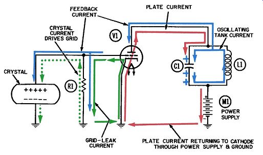
Figs. 2 and 3 show a typical crystal-oscillator circuit using a standard triode tube. The necessary circuit components, in addition to the crystal, are:
R1-Grid-drive and -return resistor.
V1-Triode tube.
C1-Plate tank capacitor.
L1-Plate tank inductor.
M1-DC power supply.
This oscillator requires energy to be fed back from the output (plate circuit) to the input (grid circuit) in order to sustain oscillation. Feedback is accomplished via interelectrode capacitance from plate to grid of the tube. There is a distinct similarity between the electrical actions in this circuit and those in the tuned-plate-tuned-grid oscillator circuit discussed in a later chap ter. The main difference between the two is that the quartz crystal here takes the place of the tuned inductance-capacitance combination in the TPTG oscillator.
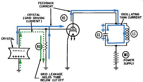
The electron currents at work in this circuit are: Grid-driving current, driven by the crystal voltage (dotted green). A small amount of grid-leak current (solid green). Plate current of the tube (red). Electrons in oscillation in the plate tank (blue) . Feedback electron current (also in blue). When the cathode is heated by the filament current (not shown) and plate voltage is applied, the tube will begin to con duct electrons from cathode to plate. This current, shown in red, flows along a closed path from cathode to plate, through the tuned L-C circuit and the power supply, and into a common ground connection where it can readily return to the cathode.
(As is true for all tube currents, a closed path must be available back to the cathode.) The sudden arrival of plate current at the tuned circuit will inevitably cause the circuit to begin oscillating at its natural frequency. Electrons (shown in blue) will then move back and forth through the inductor, between the two plates of tank capacitor C1. Fig. 2 shows the electrical conditions at the end of the first half-cycle, when the oscillating current has delivered the maximum number of electrons to the top plate of C1. The voltage at the top of C1 is now reduced to a low positive value, as shown by the single plus sign at the top plate and the two at the bottom.

Fig. 2. Operation of
a simple crystal-oscillator circuit-first half-cycle.
Since it is connected to the top of the tuned circuit, the plate of the tube will always have the same voltage as the top of the tuned circuit. The flow of a small amount of current between the two points serves to transfer the voltage from one to the other.
This flow, also shown in blue, has been labeled the feedback cur rent. During the time the upper plate of C1 is less positive than the lower one, the electrons which make up the feedback current will flow toward the plate of the tube and drive an equal number of electrons away from the grid and into the grid circuit. This occurs because of interelectrode capacitance within the tube, wherein the plate and grid act as the two plates of a small capacitor. The natural function of any capacitor is to "pass an alternating current." That is, as electrons are driven onto one of its plates, an equal number are driven from the opposite plate. The flow of electrons away from the grid is labeled "feedback cur rent" in Fig. 2 and shown in blue.

Fig. 3. Operation of a simple
crystal-oscillator circuit-second half-cycle.
Likewise, whenever the upper plate of C1 is more positive than the lower one, the feedback current will flow in the opposite direction-away from the plate of the tube and toward the tuned circuit. The withdrawal of these electrons from the tube plate now draws an equal number of electrons through the grid circuit, toward the grid. This condition is depicted in Fig. 3.
Now that we have succeeded in getting feedback current to flow in the grid circuit, we have satisfied the condition that energy in some form must be coupled back from output to input of the circuit. This coupled energy must also be of the appropriate phase so it can turn the control grid on and off at the proper times in order to sustain the oscillation. Let us now consider the action occurring in the grid circuit.
The first surge of feedback current should be sufficient to start the crystal oscillating. Fig. 2 depicts the half-cycle of oscillation when the upper face of the crystal is positively charged. This positive voltage draws a small amount of current (labeled "crystal current" and shown in dotted green) upward through grid resistor R1, performing the function recognized as "driving the grid." During the same half-cycle shown in Fig. 2, the feedback current (shown in blue) flows downward through R1. Thus it appears that the feedback and driving currents, and the respective voltages developed across R1 1:--r them, are clearly out of phase. In Fig. 3 both currents have reversed direction and so they are still out of phase. These conditions are still not conducive to oscillation. (We will return to this point shortly.) The polarities of the crystal voltage, as shown in Figs. 2 and 3, are such that they properly support the plate tank oscillation.
When the top of the crystal is positive, as in Fig. 2, the control grid will release maximum plate current through the tube. This current will reach the top of the tuned circuit ( the upper plate of capacitor C1) at the moment the voltage at this point is least positive and, in effect, will further reduce this voltage. Thus, the oscillation is sustained by strengthening it during each cycle.
Upon reaching its most positive voltage, the grid will draw some grid-leakage electrons from the cathode. These electrons will flow downward through R1 and return to the cathode, as shown by the solid green lines. The resulting small amount of negative voltage created at the top of this resistor is called the grid-leak bias.
Class-C Operation
In Fig. 3, when the crystal current drives the control grid to its most negative voltage, minimum plate current flows through the tube. This current reaches the top of the tuned circuit when the voltage produced at this point by the oscillating tank current is most positive. If the tube is being operated under Class-C conditions, then no plate current at all will flow when the grid is negative. (The definition of Class-C operation is that plate cur rent shall flow for less than half of each cycle.) The circuit here would most likely be operating under Class-C conditions. The amount of bias voltage developed by the grid leakage electrons flowing through R1 is sufficient to cut the tube off during most of the individual cycle. The voltage swing developed by the crystal can be quite substantial, 3 to 5 volts being fairly normal with most amplifier tubes. When higher-power tubes are used, more powerful oscillations are developed in the plate tank circuit. Also the feedback impulses become stronger and may drive a crystal to oscillations of 20 to 25 volts or more. In fact, it is possible to shatter a crystal by driving it with too strong a feedback impulse.
TIME CONSTANTS AND VOLTAGE STORAGE
In order for the grid-leakage current to create a bias voltage which will persist during that part of the cycle when the tube is not conducting, there must be some method of storing these electrons at the top of the resistor. This is normally performed by a grid-coupling capacitor. It is omitted in this circuit because the crystal and its electrodes to which the electrical faces are connected have sufficient capacity to store the electrons, or charge.
These inherent capacitances need be only a few micro-micro-farads in order to provide the necessary storage. The size of the grid resistor is determined to some extent by the amount of capacitance, in accordance with the time-constant formula for resistors and capacitors. This formula tells us that the time required to discharge 63.2% of any stored voltage is equal to the product of the components values involved-namely, the capacitance of the unit where the voltage (electrons or positive ions) is stored, and the resistive path over which the discharge must occur. If we assume a grid-resistor value of 300,000 ohms and an inherent crystal plus holder capacitance of 10 micro-microfarads, we can solve for time as follows:
T = 300,000 X 10^-12 = 3 X 10^-6 second, or 3 microseconds.
If a crystal has a natural frequency of oscillation equal to 500 kilocycles per second, then one cycle of oscillation will occur in 2 microseconds. Thus, we see that the time constant of 3 micro seconds is equal to one and a half cycles of oscillation.
Under these assumptions the circuit might oscillate satisfactorily, although when successful circuit operation depends on maintenance of a grid-leak bias voltage, it is usually desirable for this voltage to discharge much more slowly than is indicated here. In fact, it is more normal for the R-C combination to have a time constant equal to five or ten cycles. When we consider the equation T= RC, it is evident that the time constant can be made longer by increasing either the resistance or the capacitance in the circuit. If we increase the value of the grid resistor to, say, 1 or 2 megohms we may overcome one objection, only to create another one. This problem, known as squegging, occurs as the oscillation builds up, causing successively larger amounts of grid-leakage current to flow each cycle. Eventually this current becomes great enough to cut off the oscillation, and it will remain cut off for many cycles (perhaps even hundreds of them) until the leakage electrons can escape from storage by flowing back to ground through the grid resistor.
A much simpler means of lengthening the time constant of the grid-discharge circuit is to add a small capacitance in parallel with the crystal and grid resistor. This permits using grid resistors of nominal size, on the order of 25,000 or 50,000 ohms.
PHASE RELATIONSHIPS
Now to return to the phasing which should exist between the feedback and crystal voltages. The crystal oscillation must be sustained electrically by receiving one voltage impulse, or "kick," each time the feedback voltage reverses polarity. However, when the plate circuit is tuned to the exact crystal frequency, the condition in the previous sentence will be impossible to attain be cause the plate tank voltage and resulting feedback voltage will always be out of phase with the crystal voltage. Under such conditions, oscillation cannot occur.
By detuning the plate tank circuit slightly, it is possible to shift the phase of the feedback voltage enough that a tiny fraction of each cycle of feedback voltage will be in phase with the crystal voltage. This momentary in-phase condition is sufficient to reinforce the crystal oscillation. Such a condition is difficult to show, either with diagrams or from the waveform. However, it is subject to intricate mathematical demonstration, which we will forego in this text. If the plate circuit is detuned toward a higher frequency, the circuit is then said to be slightly inductive--an often-used descriptive term which merits considerable elaboration.
Suppose the plate circuit is tuned to a somewhat higher frequency than that of the plate-current pulses resulting from grid circuit action. Because these pulses are arriving at the lower frequency, they will not "see" a resonant tank circuit waiting for them. Instead, two reactive paths--one capacitive and the other inductive--present themselves. The pulses will be divided be tween the two in proportion to the amount of reactance presented by each path. The one offering the lesser reactance will get the larger share of current, and the circuit will also bear its name.
The smaller share of current goes over the higher-reactance path.
If the two reactances are the same, the pulses will be equally divided, of course, and the circuit is said to be resonant.
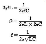
In fact, the formula for the resonant frequency of a circuit is derived from the formulas for inductive and capacitive reactance.
For example: and, 1 Xe= 2 pi fC Since, at resonance, the inductive reactance must equal the capacitive reactance, the resonant-frequency formula is derived as follows: where

X_L, is the inductive reactance in ohms, X_C is the capacitive reactance in ohms,
f is the frequency in cycles per second,
L is the inductance in henrys,
C is the capacitance in farads.
It is obvious, from the equations for X_L, and X-C, that if a cur rent is being supplied at the resonant frequency of an L-C combination, and then if the frequency of this current is lowered, the inductive reactance will be less for this lower frequency. Similarly, the capacitive reactance will be higher. Such a condition exists when the plate tank circuit is tuned above the crystal frequency-the inductor will have a lower reactance ( opposition to electron flow) and therefore claim a greater share of plate current (also called line current). Consequently, the tank is said to be tuned inductively.
It is well to keep clearly in mind exactly which frequency is being discussed. For example, in addition to the frequency of the applied current, there may be a resonant circuit frequency, and the two could be entirely different in value.
DETERMINING OPERATING FREQUENCY
If the crystal oscillates at a different frequency from that of the plate tank circuit, which circuit determines the over-all operating frequency? The answer: the circuit with the higher Q. The Q, or quality, of a tuned circuit was described in Section 1 as the ratio between the electrons in oscillation and those which drop out each cycle because of circuit losses. A "clean" tuned circuit, consisting of inductance and capacitance plus a small amount of internal resistance, may have a Q of over a hundred.
Such a circuit can be considered fairly "high quality." A crystal, on the other hand, may have a Q of over a thousand, and in special cases as high as a half million. The crystal used in the circuit of Figs. 2 and 3 could have a Q of two or even three thousand. Therefore, in this circuit the natural frequency of the crystal determines the operating frequency of the circuit, and a tuned plate-tank circuit must be operated off-resonance to sustain oscillations.