The blocking oscillator is one of the most widely used relaxation oscillators. It is often employed in the vertical section of a television receiver, as well as in the timing circuit of many radar sets, oscilloscopes, and similar electronic equipment. A typical blocking-oscillator circuit, along with the current flows during each part of the cycle, is given in Figs. 1 through 3. The circuit components and their functions are:
T1-Pulse transformer, which operates within a specific range of pulse-repetition frequencies (PRF's).
V1-Triode amplifier tube.
C1-Input and blocking capacitor.
R1 and R2-Grid-leak bias and grid-drive resistors (R2 is a potentiometer used for varying the basic repetition frequency).
C2--Output capacitor.
R3--Plate-load and isolating resistor.
M1--Power supply providing a fairly high positive voltage to the plate of V1.
CIRCUIT OPERATION
You will recall from Section 1 that feedback in the normal sense is not required to sustain oscillations in a relaxation circuit.
Let us consider that a cycle of operation begins when the grid voltage first permits plate-current electrons to pass through the tube. This plate current, shown in red on the circuit diagrams, flows through the primary winding of transformer T1 and induces a current of equal value but opposite polarity in the secondary winding. The polarity of the two windings is such that the induced current in the secondary makes the grid voltage more and more positive as the plate current increases in the primary. These are the conditions depicted in Fig. 1. In fact, the effect is cumulative--as soon as the slightest amount of plate current flows into the primary winding, transformer action responds to the changing current and begins to drive the grid positive. As the grid becomes more positive, more plate current flows, causing another positive rise in the grid voltage and a still larger plate current. Soon, maximum plate current is flowing, and any rise in plate voltage will no longer increase the current. When this happens, the tube is said to be saturated.
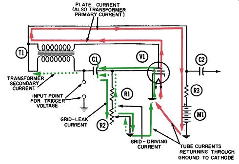
Fig. 1. Operation of
the blocking oscillator-first part of conduction period.
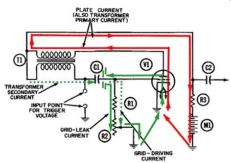
Fig. 2. Operation
of the blocking oscillator-second part of conduction period.
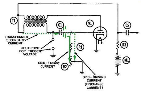
Fig. 3. Operation
of the blocking oscillator-nonconducting period. When saturation occurs,
the primary current remains steady; therefore, transformer action between
the primary and the secondary (which is dependent on a changing current)
ceases. There is a temporary stoppage of the secondary current, and also of
the grid-driving current flowing upward through R1 and R2.
Both currents are shown in dotted green lines, since they are so directly related to each other.
Meanwhile, early in the conduction cycle, the grid is actually driven slightly positive and attracts a substantial number of electrons from the plate-current stream. These grid-leak electrons, as they are called, leave the tube via the grid and accumulate on the right plate of capacitor C1. (This flow is shown by the solid green line in Fig. 1.) Because of them, the grid is prevented from rising to its full positive voltage during the transformer action. The dotted lines in Fig. 4 show how positive the grid would be driven, were it not for this accumulation of grid-leak electrons.
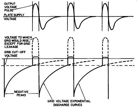
Fig. 4. Plate and grid
waveforms during free-running operation of the blocking oscillator. As soon
as plate-current saturation stops the transformer action, the negative voltage
represented by these grid-leak electrons "takes over" and begins
to reduce the flow of plate current through the primary winding. This leads
us into Fig. 2, the second part of the conduction period. Now the transformer
action is reversed-the secondary current flows in the opposite direction and
makes the grid voltage more negative.
These two events are also cumulative--less plate current leads to a more negative grid voltage, which reduces the plate current still more, and so on. The net result is that the plate current through the tube is cut off almost instantaneously. There is nothing to prevent the grid from being driven very negative by the transformer action, as it is by the negative peaks in Fig. 4.
During the much longer non-conduction period (Fig. 3), there are two currents flowing in the grid circuit. Both of them-the grid-leakage and the grid-driving current-discharge through the grid resistors.
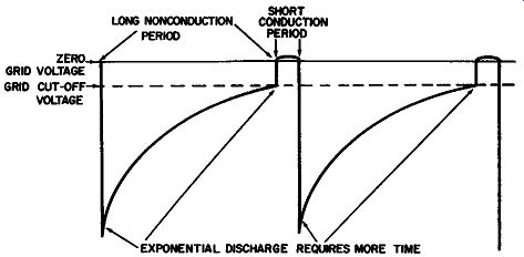
Fig. 5. Blocking-oscillator
grid waveform, showing decrease in pulse frequency when grid resistance is
increased. The discharge of grid-driving electrons, which accounts for the
sudden negative peak in the grid voltage at the start of each nonconducting
period, is completed almost instantaneously.
The flow, or "discharge," of grid-leakage electrons through the grid resistors occurs at an exponential rate which is governed by the time constant of the R-C circuit formed by capacitor C1 and resistors R1 and R2.
The exponential curve of the grid voltage during the non conduction periods in Fig. 4 represents the voltage at the grid as the leakage-current electrons discharge to ground. This grid voltage rises towards zero until it reaches the cutoff value (the point where the grid voltage is no longer negative enough to keep the plate current from flowing). With a 6SN7 tube and a plate-supply voltage of about 250 volts, the grid-cutoff voltage will be in the region of -10 volts. The cumulative effects associated with Fig. 1 then begin, and a new cycle of oscillation is underway.
As long as the values of C1, R1, and R2 do not change, the oscillation frequency of a blocking oscillator should be fairly stable. However, the number of electrons coming out of the tube and onto the grid capacitor may vary from cycle to cycle because of slight changes in plate voltage, heater voltage or temperature, etc. Consequently, each discharge period may have a slightly different negative voltage than its predecessor, and will thus re quire more or less time to reach the cutoff voltage and start a new cycle. When a blocking oscillator is running unsynchronized in this manner, it is said to be "free-running." Fig. 4 shows the grid-voltage waveform in such an oscillator. The waveform in Fig. 5 has a longer discharge time, resulting in a lower pulse-repetition frequency (PRF). This condition is achieved by moving the tap downward on potentiometer R2, so that the discharging grid-leakage electrons will encounter more resistance as they flow to ground. In other words, the time constant of the grid circuit is increased.
The opposite effect can be created by moving the potentiometer arm upward so that the leakage path contains less resistance; this will shorten each cycle and increase its PRF. Thus, potentiometer R2 acts as a frequency control (in a television receiver it is labeled the Vertical or Horizontal Hold control). Its application will be more clearly understood after you have studied the discussion on synchronization of the oscillator.
Summary
1. The grid voltage reaches cutoff and plate current begins to flow through the primary winding.
2. This increasing current in the primary winding is coupled to the grid circuit by transformer action. The transformer is connected so that this rising current causes the grid voltage to become less and less negative, thereby increasing the plate current even further.
3. The plate current reaches saturation, and can no longer increase.
4. The grid voltage becomes positive, and the grid draws grid leak current from the tube.
5. The plate current in the transformer primary collapses and, the current induced in the secondary drives the grid highly negative, cutting off the tube.
6. Grid-leakage electrons leak off until the grid voltage is again raised to the cutoff point. Plate current again flows, and the cycle is repeated.
SYNCHRONIZING A BLOCKING OSCILLATOR
To synchronize a blocking oscillator, positive-going voltage "spikes" from an external source are applied to the grid. Here they add to the existing voltage and raise it enough to trigger the cycle prematurely. Fig. 6 shows the sequence. Reading from left to right, you can see that the first cycle of oscillation begins before the trigger or synchronizing spike arrives. In the second and third cycles, the spike is applied to the grid when its voltage is very negative. Notice, however, that the combined voltages still are not sufficient to raise the grid voltage to cutoff. It is evident from Fig. 6 that the oscillator is running faster, or at a higher frequency, than the spike frequency, and cannot be synchronized.
Fig. 7 shows the opposite condition. Here the oscillator is running slower, or at a lower frequency, than that of the synchronizing spikes. This is the desirable condition, because now the oscillator can be synchronized. Positive spikes of trigger voltage are applied to the grid near the end of each non-conduction period. Now the spike is sufficient to raise the grid voltage to the cutoff point. Thus, each new cycle starts the instant a trigger spike is applied.
In a television receiver these trigger spikes are known as sync pulses and are part of the received signal. At the transmitter, their frequency is rigidly held to the correct frequency (60-cps for the vertical-sync pulses, and 15,750 cps for the horizontal-sync pulses). At the receiver the pulses are separated from the picture information and amplified to the point where they are able to trigger the blocking oscillator. It in turn generates a much more powerful pulse, at the same frequency, which is further amplified and used to sweep the beam back and forth, and up and down, on the screen.
When horizontal or vertical sync is lost in a television receiver, it is most likely caused by an increase in the natural frequency of the corresponding oscillator. As a result, the picture information does not arrive in step with (is not synchronized with) the beam as it moves across the screen. The remedy is to decrease the natural frequency of the oscillator by lengthening the non conduction period. This is accomplished by adding resistance to the grid-leak discharge path. In a television receiver, potentiometer R2 would thus be connected directly to an adjusting knob and labeled the Vertical Hold control.
A second (and less likely) reason for loss of horizontal or vertical sync is a decrease in oscillator frequency, of such magnitude that the trigger pulses arrive too early during the non conduction period (too far down on the exponential curve), in stead of near the end as they should. This is not too likely to happen, because a much greater deviation in natural frequency is required here before loss of sync occurs. When it does, the remedy of course is to increase the natural frequency of the oscillator by shortening the non-conduction period. This is accomplished by decreasing the resistance of potentiometer R2 in the grid circuit, in order to speed up the discharge time of the grid-leakage electrons so that the pulses will again trigger the oscillator.
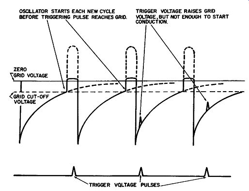
Fig. 6. Blocking-oscillator grid waveform when oscillator is running too
fast to be synchronized.
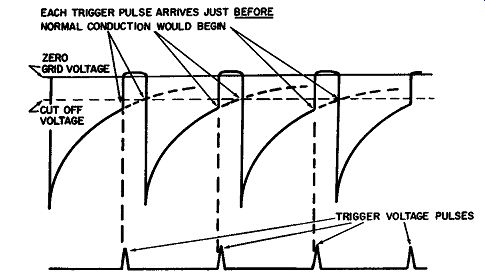
Fig. 7. Blocking-oscillator grid waveform when oscillator
is being synchronized by applied trigger voltage.
OUTPUT COUPLING
Output voltage (shown in Fig. 4) can be coupled out of the blocking-oscillator circuit via coupling capacitor C2. The output point is connected to the junction of the transformer primary and secondary windings and thus exhibits the voltage at this point.
In Fig. 1, which shows conditions during the first part of the conduction period, the current flows from right to left in the secondary winding. This can only mean that the secondary voltage is more positive at the left side winding, accounting for the initial rise in output voltage shown by the waveform in Fig. 4.
Toward the end of the conduction period, as depicted in Fig. 2, the secondary current reverses direction and flows from left to right, in accordance with the concept of counter emf discussed in Section 1. Now the voltage at the left side of the winding is negative. Actually, it does not reach its most negative value until shortly after the non-conduction period begins. This accounts for the negative peak in the output waveform of Fig. 4.
The positive output pulse can easily have a magnitude of a hundred volts or more. Even without additional amplification, it is thus able to provide a variety of functions in electronic circuits.