Prevents early failure of Ni-Cd batteries by determining proper time to recharge.
BY W.J. PRUDHOMME
------------
PARTS LIST
LED1--Any discrete light-emitting diode
Q1--P-channel junction field-effect transistor (2N4360 or similar)
Q2--N-channel junction field-effect transistor (2N3819 or similar)
Q3--Silicon switching transistor (2N2222A or similar)
R1--10,000-ohm, 1/5-watt miniature pc potentiometer
R2-Current-limiting resistor (see text for details on how to calculate value; typically about 150 ohms,1/2-watt)
Misc.--Printed circuit board or perforated board and solder clips; relay (substitutes for LED 1; see text); hookup wire; solder; etc.
----------
THE PRIMARY cause of early cell failure in nickel-cadmium batteries is internal shorting that results from allowing the battery to become too deeply discharged in service. Therefore, any electronic device that uses Ni-Cd cells should contain a low-battery indicator that trips and warns you to recharge long before the battery's "critical" voltage is reached. Though there are a number of different types of charge monitors you can incorporate into your battery-powered equipment, the lambda-diode monitor described here is more advanced than other monitors in use.
Most low-battery indicators use a transistor to switch on the drive current for a LED or meter movement. The disadvantage here is that the monitor circuit places a constant drain on the battery, even when the LED is extinguished. In low-power applications, this drain can drastically reduce the available operating time of the battery. The ideal solution is to use a circuit that draws no current from the battery as long as the supply voltage is greater than the critical potential of the battery. This is what the lambda-diode monitor does. In addition, the trip potential is adjustable over an 8-to-20-volt range, and cost is low.
Technical Details. The output potential of most batteries varies in relation to the state of charge. This relation is different for each type of battery. Lead-acid batteries, for example, exhibit an almost linear drop-off in output voltage as the cells become discharged. The same is generally true for dry cells. For Ni-Cd batteries, however, the drop-off is not quite linear.
A fully charged Ni-Cd cell has an output potential of typically 1.25 volts. The cell maintains an almost constant output potential until it is almost completely discharged, at which point, the potential drops rapidly to about 1.0 to 1.1 volts, or 1.05 volts average. A precise voltage monitor set to trip at this "critical" voltage level (or at a multiple of this potential if more than one cell is in series) can be very useful in determining the charge level of the battery.
An eight-cell Ni-Cd battery pack, for example, would have a fully charged output potential of 10.0 volts. When nearly completely discharged, the battery would have an output of 8.4 volts. If the lambda-diode monitor circuit shown in Fig. 1 were set to trip at 8.4 volts, we have a useful state-of-charge monitor for a Ni-Cd battery system.
The two-terminal, negative-resistance lambda diode shown inside the dashed box in Fig. 1 consists of one each nand p-channel FET's. (There is no "lambda" diode available commercially.) Note that in this configuration there are only two terminals, which can be labeled "anode" (A) and "cathode" (K). If the lambda diode is biased into cutoff, transistor Q3 is also cut off and LED1 is off. As battery voltage drops, a point is reached where the lambda diode abruptly conducts. This biases Q3 into conduction and turns on LEDs to indicate a low-battery condition. (The operating characteristic of the lambda diode is shown in Fig. 2.) The potential at which the lambda diode conducts can be adjusted by potentiometer R1. Resistor R2 is a current limiter for LED1. Its value is determined by Ohm's Law: R2 = E/I, where R2 is in ohms, E is the potential of the battery at the point LED1 turns on, and I is the operating current of the LED used.
Construction Details. The lambda-diode battery-charge monitor is small enough to be built into the equipment in which a Ni-Cd battery pack is used for power. Alternatively, it can be assembled as an external low-battery indicator accessory and housed in a small utility box. In either case, printed-circuit (Fig. 3) or perforated board construction can be used.
The choice of JFET's for making up the lambda diode is not critical. Almost any combination of nand p-channel devices will work as well as those specified in the Parts List.
You may want to consider substituting a small relay for LED1 to disconnect the battery pack from the load when the potential falls low enough to trigger the system. This setup will automatically protect the battery pack from polarity reversal during discharge.
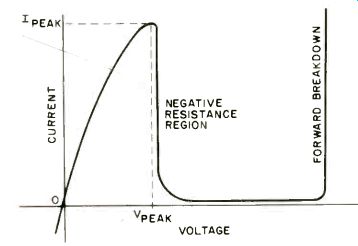
Fig. 2. Operating characteristics of the lambda-diode portion of circuit.
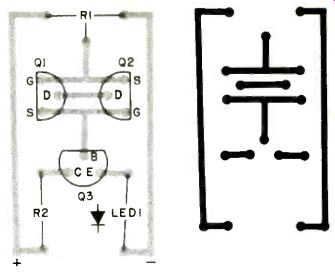
Fig. 3. Etching and drilling guide (right) with component layout (left)
can be used or a perforated board will do.
[ P-E Exp. 1980a]
Also see:
Link | --Link | --Build the Audio Detective
Low-cost Loop Antenna Extends AM Radio Reception