
Increases reception range of inexpensive AM radios by inductive linking.
BY NORMAN FALLON
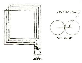
Fig. 1. Loop acts as an LC parallel circuit.
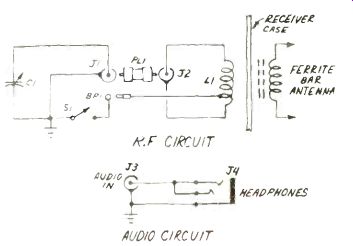
Fig. 2. Schematic shows how loop and radio antenna r-f transformer.
IF YOU'RE anxious to hear distant stations on the AM Broadcast Band-say, to catch blacked-out home-town sports events--then the Broadcast Band Loop is just what you need! When coupled to a good AM transistor radio with a built-in ferrite bar antenna, it will bring in lots of stations you could never copy before-be they TA's (transatlantics), rare "locals," or clear-channel stations from distant cities. It is easy to build and use, fairly small, and inexpensive--total parts cost is about $20 to $30! About the Loop. The use of a loop antenna is not new, but its advantages are timeless. It has good directivity, and can be easily rotated. Further, the loop works only with the magnetic portion of the radio wave (which contains both electric and magnetic fields), so it is inherently quieter than higher-gain long-wire outdoor antennas. The loop contains no fragile semiconductors and requires no power supply, unlike the "amplified loops" that some MW DX'ers are now using.
A simple loop antenna is shown in Fig. 1. It's an electrically short loop consisting of turns of wire with a total length much less than a wavelength.
Medium waves are fairly long, e.g. 500 m (1640 ft) at 600 kHz! Obviously this loop or an outdoor long-wire are the only real options.
The loop is really an inductor. When shunted by variable capacitor C, the combination can be tuned to resonance. Its nominal directional pattern (Fig. 1) is a figure eight, with maximum response in the plane of the loop.
Turning the antenna broadside to a station will cause an appreciable drop in signal strength.
Selectivity is another loop characteristic. The antenna favors signals at the resonant frequency at the expense of those nearby. Its response gets progressively narrower as its Q increases (which varies directly with the C/L ratio). For our purposes, we'll want as high a Q as possible.
We have adapted the loop to better serve our purpose by eliminating the direct connection between the Loop and the receiver. Experience indicates that unwanted signal pickup occurs when a transmission line is used to couple signals to the receiver's antenna input jack (if there is one). In this design (Fig. 2), signals are coupled inductively, simply by positioning the built-in ferrite bar close to the loop base. This offers the advantage of being able to adjust the degree of coupling between the coils to suit variations in signal strength. Operating the loop and ferrite bar in tandem will yield a cardioid directional pattern due to interaction between the coils.
Further flexibility is afforded by a switch which shorts out one turn of the Loop when closed. This is often desirable when working the high end of the MW band, since a decreased L requires more C for resonance. The result is a higher Q, and slightly less gain. In most cases, though, the effect on signal strength will not be noticed-but the sharpened tuning will be greatly appreciated. It's easy to see that the L1 and the ferrite bar in the receiver act as an r-f transformer. The "audio circuit" has been included as an operator convenience. To best work DX, headphones should be used.
They are more sensitive than loudspeakers, so it will be easier to hear weak signals. The acoustic isolation from background noise will also come in handy-you'll be able to listen without bothering others around you, and vice versa.
To accomplish this, audio will be coupled from the earphone jack on the receiver to jack J3 by a short patch cord. Make use of the new crop of high-sensitivity, lightweight (Mylar transducer) stereo headphones, which require only a few milliwatts of drive.
It's also wise to use battery power rather than an ac battery eliminator, as hum problems can arise. Of course, if you don't want to use phones or already have a mono miniature/stereo phone jack adapter, the audio circuit can be ignored.
Physical Construction. The Loop's frame will be assembled first, using doweling, two pieces of hardwood, aluminum tubing and aluminum U-channel. Refer to Fig. 3.
First, take two pieces of 1/2-inch (1.3-cm) ID seamless aluminum tubing, 34" (86.4 cm) long, and flatten the center 11/2" (3.8 cm) in a vise as shown in step 1. (Steps are shown in Fig. 3.) Drill a 7/32-inch (5.6-mm) hole in each tube at the center point. Then drill two 5/32-inch (4-mm) holes 6" (15.2 cm) from the center point on each length of tubing. Next, drill two 1/8-inch (3.2-mm) holes 16.5" and 15" (41.9 and 38.1 cm) from the center point on each length of tubing.
Center-drill 1/2-inch (1.3 cm) holes 1/4 inch (6.4 mm) deep on each of three 2 5/8-inch (6.7-cm) lengths of 3/4-inch (1.9-cm) doweling. File six grooves 3/8" (9.5 mm) apart on the dowels, spacing the outer ones 3/8" (9.5 mm) from each end. Take a 1 2 1/4-inch (31.1-cm) length of 1/2-inch (1.3-cm) doweling and drill two 1/6-inch (3.2-mm) holes 1 1/4" (3.2 cm) and 2 3/4" (7cm) from one end. Repeat four times. Then, glue the dowels together to form three T-shaped wire supports as shown in Step 2. Save the remaining dowel for later use.
Form a cross by overlapping the two lengths of tubing. Line up the center holes and secure with a 1/4-20 x 1 inch bolt, flat-washers, and wing nut. Slide the Tee's into ends B, C, and D of the cross until the holes line up. Secure the Tee's in the tubing with 1/4-inch self-tapping sheet metal screws (Step 3). Form four support braces from 9-inch (23.9-cm) lengths of 1/2" x 1/2" (1.3 cm x 1.3 cm) aluminum U-channel. Drill two 11/64-inch (4.4-mm) holes 1/4" (6.4 mm) from each end.
Then fasten the braces to the cross by lining up holes and using 6-32 x 1 inch machine screws, flatwashers, and nuts. Two lengths of channel should be on opposite sides of the tubing at each juncture.
Now prepare the fourth Tee by center drilling a 1/2-inch (1.3-cm) hole 1/4" (6.4 mm) deep on one long side of a 4"x 1 1/4" x 3/4" (10.2 cm x 3.2 cm x 1.9 cm) block of hardwood (Step 4). Drill a 3/16-inch (4.8-mm) hole /6" (2.2 cm) from one end of the block for the center conductor pin of J2, an SO-239 coaxial connector. Then drill a 3/16-inch (4.8-mm) hole 9/16" (1.4 cm) away or each side of the center conductor hole for two securing screws.
File seven grooves 3/8" (9.5 mm) apart, spacing the HOT END groove 5/16" (7.9 mm) from the edge of the block. Drill a 1/6-inch (3.2-mm) hole in the center of both the HOT and GROUND END grooves. Then drill a 3/16-inch (4.8-mm) hole 3/8" (9.5 mm) to the right of the HOT and GROUND END holes on the top (un-grooved) side of the block. Mount solder lugs above each hole, using No. 6 x 1/2" wood screws.
Referring to Step 5, prepare an SO-239 coaxial jack, cutting two corners with a hacksaw to fit the hardwood block. Solder one end of a 6-inch (15.3-cm) length of hookup wire to the center conductor pin of J2, and thread it through the center conductor hole. Then secure J2 to the wood block using No. 6 x 1/4" wood screws, looping one end of a 4-inch (10.2-cm) length of hookup wire under the head of the screw nearest the GROUND END groove. Thread the other end through the hole in this groove and attach to the nearest solder lug (above J2). Trim excess. Attach the free end of the center conductor wire to the other solder lug, trimming excess.
Glue the hardwood block to the remaining 12 1/4-inch (31.1-cm) dowel to form the fourth Tee. Insert the Tee into the remaining corner of the cross (A), lining up the holes. Secure with 1/4-inch self-tapping sheet metal screws. Then drill a 3/16-inch (4.8-mm) hole 3/8" (2.2 cm) above the bottom of the vertical tubing (above corner A). Make the hole slightly more than 3/8" (9.5 mm) deep.
Take one end of a 74-foot (22.6-m) length of 18or 16-gauge (solid or stranded, bare or insulated-enamel or plastic-almost anything will do!) copper wire, thread it through the HOT END hole and solder it to the HOT END solder lug (trimming excess). Then tightly wind the wire around the cross, using the Tee grooves as guides to make six turns in all. Thread the free end through the GROUND END hole and solder to the lug, trimming excess.
Remove the insulation (if any) from the wire near corner A on the fifth turn.
Solder one end of a 4-inch (10.2-cm) length of hookup wire to this point.
Leave the other end free for the moment.
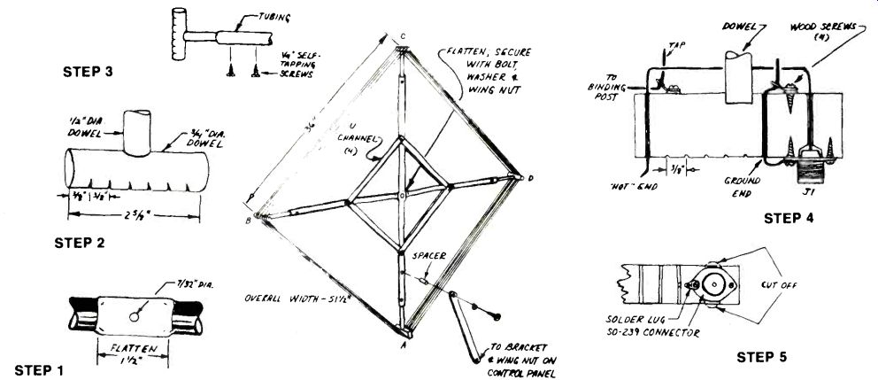
Fig. 3. Above are directions for constructing the frame for the loop.
Aluminum tubing, U-channel, and wood dowels are used.
Steps 1 to 5 are referred to in the text.
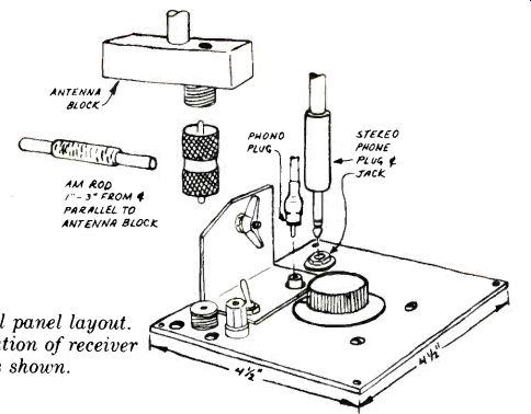
Fig. 4. Control panel layout. Proper orientation of receiver rod antenna
is shown.
Control Panel Construction. We'll now assemble the Loop's Control Panel. It should be fashioned from a 4.75" (12.1-cm) square piece of 1/16-inch (1.6-mm) aluminum plate.
Physical layout is flexible, but use Fig. 4 as a guideline. Form a support bracket from aluminum stock, or use a commercial aluminum angle about 2 1/2" x 1 1/2" x 1 1/2" (6.4 cm x 3.8 cm x 3.8 cm). Install the bracket centered along one side of the aluminum panel.
Then drill mounting holes for an SO-239 coaxial jack-this should be set back 1" x 1" (2.5 cm x 2.5 cm) from the corner nearest the notched side of the bracket-and for the main tuning capacitor, switch S1, binding post BP1, and the RCA phono and headphone jacks (if desired).
A note about capacitor C1-any surplus, multi-gang variable capacitor may be used. Total maximum capacitance should be about 1200 pF. Suitable models are available from most surplus sources with an approximate cost of $3.00. If, however, you have trouble finding a capacitor on the surplus market, buy three 365-pF AM tuning capacitors and gang their shafts together. After installing all components, wire the Control Panel in accordance with the schematic (Fig. 2) using 18-gauge solid hookup wire. Try to keep all leads as short as possible.
The Control Panel should be mounted in a cutout on a rotatable platform--a lazy susan arrangement.
The platform should be big enough to accommodate your AM receiver also, since it must be rotated in step with the Loop.
Once the Panel is mounted, drill a 7/32-inch (5.6-mm) hole in the support bracket 3/8" (9.5 mm) down and 1" (2.54 cm) over from the' un-notched top corner. Then drill 7/32-inch (5.6-mm) holes along the center line 3/6" (9.5 mm) from each end of an 11 1/4' x 1" x Ye" (28.6 cm x 2.5 cm x 9.5 mm) hardwood strip. Attach one end of the strip to the support bracket using a 10-20 x 1" hex head bolt, a hex nut as a spacer between the strip and bracket, and wing nut. Keep the wing nut relatively loose. Now secure the other end of the strip to the Loop frame using a 10-32 x 11/2" bolt, washer, and a 3/4' (1.9 cm) spacer. Use the 3/16-inch (4.8-mm) hole previously drilled above the bottom of the vertical tubing.
Attach the Loop frame to the Control Panel using PL1, a double male uhf coaxial adapter (Amphenol 83877), between jacks J1 and J2. Then connect the free end of the hookup wire from the loop to binding post BP1. Tighten the hardware holding the hardwood strip. Leave S1 open, and position your AM receiver below the Loop, orienting its rod antenna as shown in Fig. 4. The two coils should be about 1" to 3" (2.5 cm to 7.6 cm) apart.
Using the Loop. Tune the receiver down to the low end (540 kHz) of the AM Broadcast Band. Turn C1's tuning knob so that the plates are fully meshed. Then, carefully tune in an audible signal using the receiver's tuning capacitor. Slowly unmesh C1's plates (reduce capacitance) until the signal peaks strongly. You have now tuned the Loop to resonance at this frequency.
It's possible that loading effects by the Loop may "pull" the receiver off its dial calibration. If this occurs, just continue to adjust both C1 and the receiver's tuning capacitor for maximum intelligibility. You'll probably find that the two controls interlock, but with a little practice you'll be quickly zeroing in on the station you're after. Try rotating the loop to get an even stronger signal. Best results will be obtained when the plane of the loop extends in the direction of the desired signal. You can also use this directivity to null out an interfering station on the same frequency--turn the loop broadside to the offending signal.
With S1 open, the Loop can be tuned just about to 1600 kHz. It also has maximum gain in this position.
But there are times when a bit more selectivity is desirable over gain-for example, when two fairly strong stations are a few kHz apart. This is particularly true when trying to work the "splits"-foreign stations operating on odd frequencies not multiples of 10 kHz. In situations like this, close S1.
This shorts out the bottom turn of the loop, giving a higher Q. It also gives you a bit more "room" on C1 at the top end of the band.
Other Suggestions. The "pulling" action mentioned earlier can cause you to get "lost" in terms of frequency.
To prevent this, prepare a list of strong signals in your area, noting them by call letter and frequency. You can then use them as frequency markers to chart your way across the band. It's also a good idea to get a complete list of North American AM stations--especially if you want to DX the band.
Several are available, listing stations by call letters, power output, frequency, and geographical location.
Another system variable is the amount of coupling between the Loop and the rod antenna. This should be varied to suit signal strength, but cannot accurately be predicted without experience with your particular receiver. While it should vary between 1 and 3 inches, experiment for best results.
To make tuning easier, a vernier (0 to 100) tuning knob can be used with C1. Once you have properly tuned a station in, record its frequency, direction toward which the Loop is turned, position of Si, and the amount of capacitance needed. Keep all this information for future reference.
FRAME BILL OF MATERIALS
2-42 inch lengths of 1" ID thin-wall aluminum tubing 4-14-inch lengths of 1" wood doweling 3-2%-inch lengths of 3/4" wood doweling 4-12-inch lengths of 11" x 1" aluminum U-channel 1-Block of hardwood 4" x 11" x 3/4" I-Strip of hardwood 11 W x 1" x 4" 1-10-32 x 1 1/2" bolt and washer 1-3/4-inch spacer to fit above.
1-1/4-20 x 1" bolt, washers, and wing nut 4-6-32 x 1" machine screws, flatwashers, and nuts 4-No. 6 x 1/2" wood screws 8-1/4" self-tapping sheet metal screws
PARTS LIST
BPI-5-way binding post
C1-1200-pF (total) multi-gang variable capacitor
J1, J2-Uhf coaxial jack, SO-239
J3-RCA phono jack
J4-Open-circuit stereo headphone jack
L1-6 turns of 16- or 18-gauge copper wire wound on loop frame
PL1-Double male uhf coaxial adapter (Amphenol 83-877, Lafayette 42 69064 or equivalent)
S1-SPST switch
Misc.--4.75" square I/16-inch aluminum plate, tuning knob, machine hardware, hookup wire, solder, etc.
Also see:
Perf Board Wiring Techniques for Experimenters
The "Bucket Brigade" Audio Delay