BY DANIEL METZGER
Measures effective AC voltage rather than the usual average values.
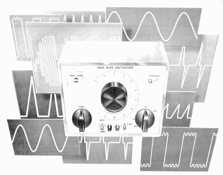
EVENTUALLY, most serious electronics experimenters find a need to measure the power content of an odd-shaped waveform. This might occur in measuring the output of a class-C amplifier, audio, video or noise signals; power supply inverter waveforms; or just plain power supply ripple.

Fig. 1 Schematic of the voltmeter.
The amplified input signal illuminates I1, which causes the resistance of PC1 to change.
This brings about imbalance in the bridge circuit and meter goes off null.
===========
PARTS LIST
C1--0.05-µF, 500 volt capacitor
C2 through C5--50-pF trimmer
C6--0.22-µF Mylar capacitor
C7--0.022-µF Mylar capacitor
C8-0.(X)22-µF capacitor
C9--220-pF capacitor
C10--20-pF capacitor
C11--0.1--µF capacitor
C12--10-pF capacitor
C13,C14--5-µF, 15-volt electrolytic
C15,C16--1000-µF, 35-volt electrolytic
C17, C18--100-µF, 25-volt electrolytic
C19--330-pF capacitor
D1 thru D4, D9--1N914
D5 thru DR 1N4002
F1--1/8-ampere slow-blow fuse
I1--#47 pilot lamp
IC1--LM318 opamp
J1,J2—Five-way binding posts, one red (J1), one black (J2)
LED 1 ,LED2--Light emitting diode
M1--100-0-100-µA meter
PC1--See text
Q1 .Q2--2N3819,MPFI02, or similar
Q3,Q7--TIP29 or similar
Q4,Q8--TIP30 or similar
Q5, Q6--Any small-signal silicon transistor
R1,R3,R9--1-megohm, 1%, 1 watt resistor
R2,R10--100-ohm, 1% resistor R4--1(X10-ohm, 1% resistor R5--1-megohm, 1% resistor (try for 990k)
R6--10.000-ohm, 1% resistor R7 909,000-ohm, 1% resistor (try for 9001s)
R8 100,00)-ohm, 1% resistor
R 11--10-ohm, 1% resistor R12 I-ohm, 1% resistor
R1 13,R14,R48--100,0(0 -ohm resistor
R16 82 -ohm resistor
R 18--68(X) -ohm resistor
R20,R21 10 -ohm resistor R22.R23 100 -ohm resistor R24,R25 2200 -ohm resistor R26,R27--33 -ohm, I -watt resistor R28,R29--4.7 -ohm resistor R30,R31,R32,R46,R47 10,00 -ohm resistor R33--1800 -ohm resistor R34 3300 -ohm resistor R35--I8,(XX)-ohm resistor R36--82(0 -ohm, 'h -watt resistor R37,R38--2700 -ohm 5% resistor R39,R49 7500 -ohm 5% resistor R40,R41 680 -ohm resistor R42,R43,R44,R45--1(5)0 -ohm resistor R IS--50,000 -ohm linear-taper potentiometer R 17--1000 -ohm linear -taper potentiometer (see text)
R19--10,000 -ohm, trimmer pot
S1--Dpdt center -off toggle switch
S2 8 -position, 2 -pole rotary switch
S3--Dpdt switch
T1-- 36-V CT, 0.1-A transformer (Stancor 8611 or similar)
Misc.--Suitable enclosure, dial plate and knob for R17, pointer knobs (2). press-on type, mounting hardware, etc.
===========
When the time comes, the experimenter will discover that a standard VOM or DVM simply won't provide true rms readings! An rms voltmeter is needed for this purpose. Unfortunately, this is a rather expensive instrument.
With the plans presented here, however, a true rms voltmeter can be built for only about $30. To fully understand how this is accomplished, let's first examine what rms means.
What Is RMS? Rms values allow the expression of the average power content of an ac waveform whose instantaneous power varies from zero (at the zero crossing) to some high value at the voltage peak. In practice, rms means "equivalent to dc." Mathematically, given a voltage and a resistance, power is calculated as P=E^2/R. The "equivalent-to-dc" voltage for a continuously varying ac voltage must be calculated by squaring the voltage at each instant, averaging the infinite number of instantaneous values produced (taking the mean), and then extracting the square root. Hence, the term Root of the Mean of the Square (RMS). For anything beyond a simple rectangular waveform, this rms technique involves calculus. For sine waves only, it produces ERMS = EPK(SINE)/\ =0.707EpK. For periodic waveforms that cannot be mathematically expressed, the rms technique requires iterative computer analysis. For completely un-definable ) waveforms such as noise, however, we have to go back to the rms voltmeter.
This may be a good place to observe that the time-honored VOM and most DVMs actually respond to average voltage (not rms) on their ac scales. The average value of one half-cycle of a sine wave is 0.637 of its peak value, or 0.901 of its rms value.
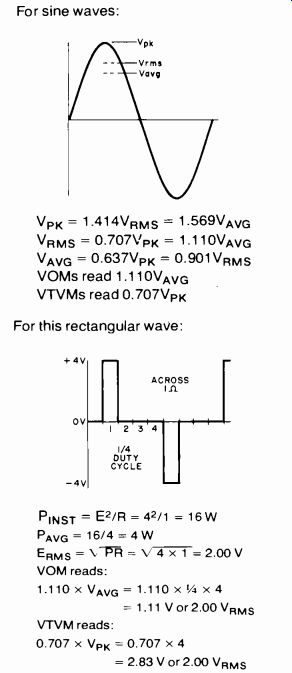
The meter scales are calibrated in rms, but this calibration is valid for sine waves only. VTVMs and FET meters generally respond to peak voltages on their ac ranges. Again, the meter scales are calibrated for rms readout on sine waves only. Consequently, a VOM or VTVM can display different and incorrect conclusions about a 25% duty cycle waveform, as illustrated in boxed section below right. Interestingly, most VOMs err in one direction on non-sine waves, while VTVMs err in the other.
The majority of true rms meters operate by electronically squaring and averaging the input signal, or by taking the log of the signal, doubling it, then taking the antilog. Building such a meter is best avoided because of its circuit complexity. The meter discussed here takes the direct approach of amplifying the input waveform and using its large signal to turn on a conventional incandescent lamp. The brilliance of the lamp is sensed by a photocell so that comparisons between ac and equivalent dc voltages can be made. In operation, the amplifier gain is adjusted until the lamp reaches a predetermined brightness, and the rms voltage is then read off a calibrated "gain" control.
Circuit Description. As shown in Fig. 1, resistors R1 through R9 provide voltage divisions by progressive factors of ten while maintaining a 1-megohm input resistance. Capacitors C2 through C/O provide identical division ratios at high frequencies while maintaining an input capacitance of 20 pF. Without these capacitors, the reactance of any stray wiring capacitance would completely swamp the resistive dividers above approximately 50 kHz, resulting in false division ratios. Resistors R10 through R12 are used in the measurement of current.
============
VTVM AND VOM ERRORS
========
Source follower Q1 provides an almost infinite input impedance for the amplifier, while FET 02 provides compensation for variations in Q1 source voltage with temperature. Both Q1 and Q2 should be well matched-zero volts between their sources with the input grounded and control R15 (zERo) near the center of its rotation. Also, the transistor cases should be thermally bonded.
Op amp IC1 has a gain between 10 and 100, depending on the setting of the CAL (R19) and NULL (R17) controls. Capacitor C12 compensates for stray capacitance in the R16-R17 leg, and is selected for good high-frequency response. Components R20, R21 and C11 are required to prevent high-frequency oscillation via power supply coupling. A complementary symmetry voltage follower (03 and Q4) provides the high current required by lamp L1.
The sensitive surface of photoresistive cell PC1 is butted to the lamp and secured in place with opaque heat--shrink tubing. The photocell forms one arm of a Wheatstone bridge, with R30--R32 as the other arms. At one particular lamp intensity, the cell resistance will equal 10,000 ohms and meter M1 will indicate zero. For unbalance currents of about 25µA, D1 and D2 will begin to conduct, shunting the meter with R33.
This makes it easier to find the null by reducing the meter sensitivity for off-null settings. The meter can be switched to zero out dc voltage at the amplifier output when the input is grounded.
In the prototype, balance was achieved with 2 volts rms (or dc) across the lamp. For sharply peaked waveforms, it is possible that the peak voltage might exceed the approximately 10-volt limit of the amplifier resulting in distortion of the waveform. Diodes D3 and D4 detect such peaks slightly before the threshold of distortion, causing the front panel positive (LED1) or negative (LED2) over-peak indicators to glow.
The power supplies are well filtered by the emitter follower action of Q7 and Q8.
Regulation is not required because the differential amplifier and bridge circuits remain balanced in spite of power supply voltage variations.
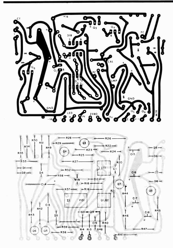
Fig. 2. Actual-size foil pattern for main pc board is a t top, component
installation immediately above.
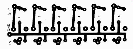
Fig. 3. Components for attenuator can he mounted on board similar to
that at left. Only four sections are used in this case.
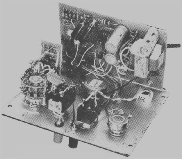
------- Photo shows how author mounted components in prototype of
voltmeter.
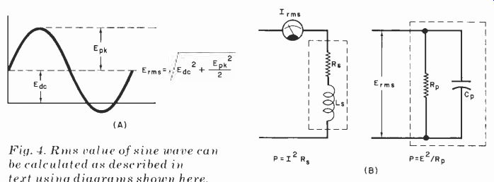
Fig. 4. Rms value of sine wave can be calculated as described in text
using diagrams shown here.
Construction. Few of the components are critical and substitutions are possible. The NULL potentiometer (R17) should be of the highest quality since accuracy of the instrument depends on reading its angular position. Resistors R1 through R12 directly affect the accuracy and should be held to ±1%. For the voltage dividers, it is the resistance ratio that is important. Ceramic trimmer capacitors hold their values better than compression types and are recommended for C2 through C5. Transistors
Q3 and Q4 may dissipate as much as 2 watts and must have heat sinks.
Using an LM318 for IC1 results in a 400-kHz bandwidth. A µA741 reduces the bandwidth to about 20 kHz. Any photoresistive cell having a resistance of 10,000 ohms when illuminated by a #47 lamp with 1.5 to 2.5 volts dc applied to it will work for PC1.
The bulk of the circuit can be assembled on a pc board using the foil pattern and component layout shown in Fig. 2.
The front-end attenuator can be built up on a small pc board like that shown in Fig. 3. Fixed and trimmer capacitors are mounted on the foil side and the resistors on the other. This board supports the first four attenuator elements. (Two sections on this small board will be unoccupied.) Once the components are mounted on the board, the pc assembly can be wired to the appropriate lugs on S2 with short lengths of hookup wire. The four remaining attenuator sections are resistors that can be mounted directly on S2.
As shown in the photograph, on the front panel are the meter, two over-peak LED's, R17 (NULL), R15 (zERo), S3 (NULL/ZERO), S1 (AC, DC POWER ON-OFF), S2 (RANGE) and input jacks J1 and J2.
These components can be mounted as desired on the front panel, leaving enough room around R17 to accommodate a calibrated dial plate. Press-on type can be used to identify controls.
Calibration. Set the NULL control (R17) to its minimum resistance. With S3 at ZERO, connect J1 to J2 and adjust R15 (ZERO) for no meter deflection (center zero). Set S2 to the x 1V position and S3 to NULL. Apply an accurate 1-volt dc between J1 and J2 (positive to J1) and adjust the pc board mounted R19 for a zero meter indication.
Mark the NULL dial plate with a 1, then apply 2, 3, etc., up to 11 volts dc, zeroing the meter with the NULL control and marking the dial as you go. If desired, you can apply a 60-Hz sine wave of known rms value to verify the "equivalent-to-dc" function.
The S2 trimmer capacitors can be adjusted with the aid of an audio generator. Null the meter to read a 60-Hz sine wave someplace on the x1 range.
Without changing the generator output level, raise the frequency to 50 kHz and adjust C5 for a null at the same spot on the dial. Repeat this for C4, C3 and C2 on their ranges. Alternately, the trimmer capacitors can be adjusted for the cleanest 10-kHz square-wave response with a scope probe across 11.
Use. Here are some guidelines for using the rms meter.
When there is an ac or combined ac and dc voltage across an unvarying (pure) resistance, the rms value of the voltage can be used to compute the average power in the resistance by the equation PAVG = ERMs2/R. Similarly, if the rms current through an unchanging resistance is known, then PAVG = IRMS2 R. Note that unlike many rms meters, the meter described in this article can indicate the rms value of a waveform having a dc component. This do component cannot be simply added to the rms value of the ac component to obtain the rms value of the total waveform. For sine--wave ac components, the rms value can be calculated as illustrated in Fig. 4. For other waveforms, it's either calculus or the dc-coupled rms meter.
An rms measurement cannot be applied to the calculation of power where the load impedance is partly reactive.
However, if the numerical value of the resistive part of the load can be determined, true power can be calculated as shown in Fig. B, since the reactive portion consumes no power.
The rms measurement is also not appropriate for calculating the average power delivered to devices having changing ohmic resistance. Examples of such devices are diodes, SCRs, switching transistors and the plate or collector of a class-C amplifier.
For such devices, measure the average voltage and current for the device and calculate: PAVG= IAVGEAVG
If current flows always in one direction, a VOM on the dc range can be used. If ac is involved, you must use a meter that measures the average absolute (without regard to sign) value of voltage and current.
A VOM or average-reading DVM on the ac range fills this function if the readings are multiplied by 0.901 to change the rms calibration to average calibration. Be wary of such meters on the ac ranges since many of them have upper frequency limits below 1 kHz.
Source: (Popular Electronics Electronic Experimenter's Handbook (1982)
Also see: Precision References for Current & Voltage
Listen To A New World Of Sounds With Ultrasonic Detector
Add A Clipping Indicator To Your Audio Amplifier