Detects when conditions for ice on the road exist, even in the dark or if air temperature seems too warm.
BY THOMAS R. FOX
ROAD-SURFACE icing is one of the most dangerous hazards of winter driving. To warn drivers, ice-warning indicators for automobiles have indeed been developed. However, most of these indicators merely monitor air temperature a few inches from the road and alert the driver when that tempera ture falls to about 36° F. Unfortunately, this approach can deliver false alarms or, worse, fail to indicate danger when air and road temperatures are different.
The infrared road icing alert (IRIA) system described here overcomes this problem by responding to both air and road temperatures. It senses infrared radiation emitted by the road and warns drivers both audibly and visually that the conditions for icing are present.
Sensor Operation. The sensor used in this project is a thermistor--a semi conductor device whose electrical resistance varies with temperature. Like any other material body, a thermistor can change temperature by conduction or radiation. As shown in Fig. 1, conduction is the exchange of heat between the air surrounding the thermistor and the thermistor, or the exchange of heat between the thermistor and any object making direct contact with it. In some remote cases, thermistor body tempera ture changes can occur by heat flowing along the thermistor leads. In all cases, the heat flow continues until the thermistor is at the temperature of the heat source and thermal equilibrium between the two is reached.
Temperature change through radiation occurs when the thermistor intercepts infrared radiation, that is electro magnetic radiation whose wavelength is just longer than visible light. When exposed to infrared radiation, the thermistor increases its internal temperature until it re-radiates energy at the same rate as it is being absorbed, and thus reaches equilibrium. Its electrical resistance, of course, changes accordingly.
A thermistor can also be heated by current flowing through it. However, in most applications, this current heating is small enough to be ignored.
While one does not usually consider ice or a road surface at or below freezing to be a source of infrared radiation, these objects like any in the universe that are above absolute zero (-273.16 °C.), emit some electromagnetic energy. The magnitude and spectrum of the radiation vary with temperature and the characteristics of the radiating body in a fairly complex way, but it is sufficient for our purposes to note that as temperature rises, the radiation increases in intensity and the peak of its spectrum moves to shorter and shorter wavelengths. Objects at normal temperatures (including the freezing point) radiate substantial infrared, to which a thermistor can respond.
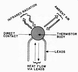
Fig. 1. How the temperature of a thermistor can change.
The Sensor Head. If a thermistor is mounted at the focal point of a parabolic reflector (a curved surface that has the property of focusing all incoming rays to a single point), and if the open end of the reflector is covered with a material that keeps air from circulating around the thermistor but allows infrared radiation to pass through, a sensor for infrared radiation is produced. This is shown in Fig. 2. Since the reflector and thermistor are not thermally insulated, the thermistor will have some response to ambient air temperature.
The reflector arrangement shown in Fig. 2 is the approach used in the IRIA project. Such a sensor is mounted to the underside of the vehicle front bumper, with the open end facing the road underneath the vehicle. The temperature of the thermistor represents a weighted average of the road and air temperatures--with the road temperature pre dominating. If there were a perfect vacuum surrounding the thermistor, and the thermistor leads had the absolute minimum of support, the thermistor temperature would closely approximate that of the road.
The Sensor Assembly. The thermistor used in the author's prototype has a resistance of 1000 ohms at 25 deg. C, is relatively small and inexpensive. It has a time constant of 10 seconds, and a diameter of 0.1 inch (see Parts List).
The parabolic reflector used was a 4" type salvaged from a discarded lantern flashlight. Other sizes of reflectors can be used, but experiments show that a 2 1/2" diameter is the smallest that can be used efficiently.
To determine the focal point of your reflector, remove the bulb and holder and temporarily attach a piece of styrofoam or balsa wood to the back of the reflector so that it covers the bulb holder hole. Stick a thin wood toothpick into the exact center of the holder hole so that it is supported by the styrofoam or balsa. On a clear, sunny day, aim the open end of the reflector to the midday sun until the toothpick begins to smoke.
Remove the reflector from the sunlight and note that the charred part is at the reflector's focal point. Carefully measure and record the distance from the bottom of the reflector to this focal point as this is where the thermistor will be placed for maximum effect.
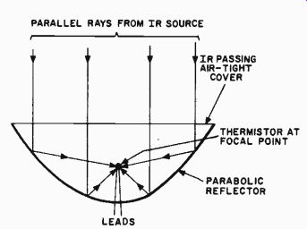
Fig. 2. A parabolic reflector focuses infrared rays onto the thermistor.
The reflector is mounted on a short length of 1" x 2" wood board, which in turn, is affixed to the car underside, far enough from the front so that direct sun light will not strike the sensor. Once you determine where the wood element is to be mounted, you can then determine its length and method of mounting.
After the wood has been cut to length, the reflector is mounted to it using a pair of wood screws or epoxy as shown in Fig. 3A. After securing the reflector, care fully drill two 1/16-inch holes, 1/4 inch apart and straddling the center point, through reflector and wood support. Cut two pieces of small-diameter insulated sleeving, about 1/8 inch shorter than the "focal length" previously determined.
Mix a small batch of quick-setting epoxy and place some on each thermistor lead from the body to about PA inches down. Slip the sleeving over each thermistor lead as shown in Fig. 3B.
Insert the bare (un-sleeved) thermistor leads through the two 1/16-inch holes drilled through the wooden support. As shown in Fig. 3C, adjust the height of the thermistor body so that it is centered at the "focal point" previously recorded.
Use a dab of epoxy at each lead to secure the two leads to the board. Make sure bare leads do not make contact with the metal reflector.
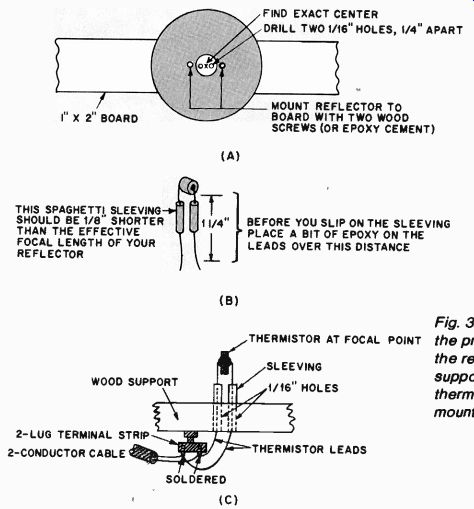
Fig. 3. Diagrams showing the procedures for mounting the reflector on its
support (A), preparing the thermistor (B), and mounting the thermistor (C).
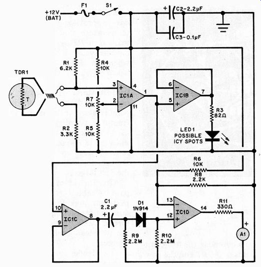
Fig. 4. The thermistor is part of a bridge that drives comparator IC1A.
When this comparator turns on (detected temperature below preset), it activates
a LED and an audible alarm.
On the underside of the board, mount a two-lug terminal strip and connect both the two thermistor leads and a small two-conductor cable to the two terminals as shown in Fig. 3C. After the epoxy is cured, paint a thin coat of flat- black, oil-based paint on the thermistor body. Cover the open end of the reflector with a thin transparent plastic shield (transparent food packaging material or other thin flexible plastic is fine). Transparent plastics pass more infrared energy than does glass.
PARTS LIST
A1-6- or 12-volt alarm (Sonalert or similar)
C1, C2-2.2-µF, 25-volt tantalum capacitor
C3--0.1-uf, 25-volt ceramic capacitor
D1- 1N914 or similar diode
F1--1/4-ampere fuse and holder
IC1--LM324N quad op amp
LED1-orange or red LED
The following are 1/4-watt composition resistors unless otherwise specified:
R1-6.2 k-o 5%, film
R2--3.3 k-o, 5%, film
R3--82 ohm
R4, R5, R6- 10 K-o, 5%, film
R7--10 k-o, 10-turn pc mount potentiometer
R8-2.2 k-o
R9,R10-2.2 M-o
R11-330 ohm
S 1-Spst switch
TDR1-1 k-o © 25°C thermistor, (Fenwall JB31J1 or similar)
Misc.-2 1/2" or larger parabolic reflector (lantern or flashlight component), spaghetti sleeving, epoxy cement, 1" x 2" wood board, wood screws, machine screw, two-lug terminal strip, two-conductor cable, cable ties, etc.
Note: The following are available from Magicland Electronics, 4380 South Gordon Ave.. Fremont, Mi 49412: Fenwall JB31J1 thermistor at $2.95: thermistor and LM324N at $4.25 (kit IRIA 1).
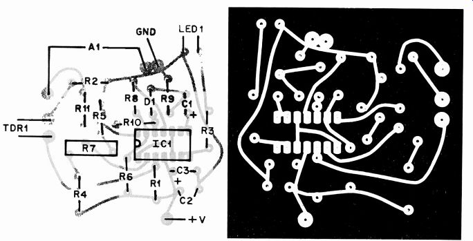
---Fig. 5. Actual-size etching and drilling guide for a printed
circuit board for the Infrared Road Icing Alert is shown above right. Component
layout above left.
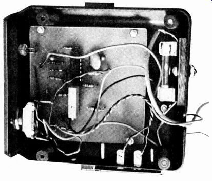
------Internal view of the author's prototype shows circuit board in
container with LED and switch on front and power leads exiting through back.
Terminal strip on side is for leads to the thermistor.
Circuit Operation. The circuit is shown in Fig. 4. At a temperature of 32°F (0*C), the thermistor called for in the Parts List has a resistance of approximately 2.8 k O.
Thus, at 32 ° F, pin 3 of op amp IC1A is just under 6.8 volts (assuming the vehicle's electrical system is delivering about 13.6 volts when the generator is operating).
The output of IC1A is coupled to follower IC1B which in turn drives LED1 through current-limiting resistor R3.
Reference voltage control R7 is adjusted so that the LED is just below the point of glowing at the user-selected "critical point" (this is usually between 32 and 36 ° F). Once R7 has been adjusted, the reference voltage at pin 2 of IC1A is just a fraction of a volt below that at its noninverting input (pin 3).
The noninverting input of IC1A is connected to the junction of R1 and TDR1 in series with R2. As the temperature of TDR1 drops, its resistance increases, and the voltage at IC1A pin 3 increases above the reference voltage applied at pin 2. This causes IC1A to switch "on" which, in turn, forces buffer IC1B to supply current to LED1 causing it to glow. This visually indicates that there is the possibility of an icy spot in the road.
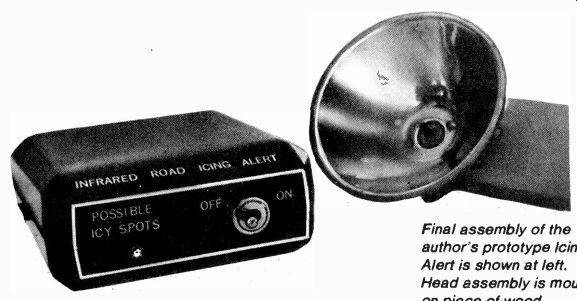
-------Final assembly of the author's prototype Icing Alert is shown
at left.
Head assembly is mounted on piece of wood with the thermistor at the focal point.
The output (pin 1) of IC1A is also coupled to buffer IC1C, which drives a differentiator consisting of C1 and R9.
The output of this differentiator consists of a positive-going pulse when IC1A switches off. Diode D1 allows only the positive-going pulse to pass to the noninverting input (pin 12) of IC1D. The inverting input (pin 13) is referenced to about 2.5 volts developed by network R6 and R8. Therefore, IC1D will switch on only when its noninverting input is greater than the reference voltage (2.5 volts). When IC1D is activated, it sup plies current to alarm Al via current-limiting resistor R11. This alarm turns on a fraction of a second after IC1A operates. After a time period deter mined by the values of R6, R8, R9, and C1, the alarm goes off. When the thermistor "sees" a higher temperature, its resistance drops, turning off IC1A and IC1B, and the LED goes dark.
The circuit is protected by fuse F1, and capacitors C2 and C3 remove volt age transients that might produce a false alarm.
Circuit Construction. Although the circuit is simple enough to use direct point-to-point wiring on conventional perforated board, an actual-size foil pat tern is shown in Fig. 5 along with the component installation. Note that TDR1, F1, S1 and A1 are not mounted on the small board. Though a single-turn potentiometer can be used for R7, a 10-turn type is recommended. If your alarm (A1) is a 6-volt version, use R11. If A1 is a 12-volt type, R11 can be eliminated. Resistor R8 determines the "on" time for the alarm. Making this resistor smaller in value increases the Al "on" time. Conversely, for a shorter "beep," increase the value of R8 to 3.3 k-ohm.
The circuit board can be mounted in almost any type of small (usually plastic) container. Power on-off switch S1 and LED1 are mounted to the front pan el. The two leads to TDR1 and the power-ground leads exit via small holes at the rear.
Initial Test. Connect a source of 12 to 15 volts dc to the pc board, and turn power switch S1 on. Adjust trimmer potentiometer R7 until the alarm sounds and LED1 glows. Carefully back down on R7 to the point where the LED just turns on.
Place the palm of your hand near the open end of the reflector for a brief period of time and note that the LED goes dark. Remove your hand, and note that after a few seconds, the LED glows and the alarm sounds off.
To create a "home-made" 37 ° F day, place the detector-reflector assembly in a common brown-paper bag and lay it on a shelf in the middle of your refrigerator (not the freezer!). Leave the sensor in this position for about 15 minutes. Since the temperature of the sensor is now approximately 37 ° F (the usual temperature that a refrigerator is set to), adjust R7 until the LED just turns on. The system is now set up to sound off when the sensor "sees" a temperature below 37°F.
Installation. The sensor must be mounted under the vehicle, the open end pointed down at the road, and protected from direct sunlight. Any means can be used to affix the wood sensor support to the vehicle frame. Make sure that the reflector does not extend too far below the vehicle, or it will be knocked loose at the first large bump.
After the sensor is mounted, carefully pass its cable through the engine compartment making sure that the cable does not contact any hot or moving elements. Cable ties can be used to secure the twin-lead conductor to appropriate supports.
The slender sensor cable is passed through the firewall and snaked to the upper part of the dashboard where it is connected to the electronics. The ground can be made to any metal part of the chassis, and the +12 volts should be obtained from any source that is "live" when the ignition key is used.
If the sensor has been calibrated at 37° F, you will have to wait until the ambient temperature drops into the 30's. A nearly perfect day would be one with cloudy skies and a temperature well below freezing in the morning, and an afternoon temperature over 38°F.
Park the car in the shade so that the reflector is positioned over an accurate thermometer placed on the ground. If you are on the cautious side, adjust R7 until the LED barely lights with a ground temperature of 36°F. If desired, you can make the calibration at lower temperatures of about 32 or 33°F. If the weather is too warm, you can always use a pan of ice under the reflector to simulate 32°F.
The only maintenance required is keeping the reflector clean. You should wipe the reflector transparent cover at regular intervals. Contingent on the amount of road tar, sand, pebbles, etc., on the roads you use, you might have to replace the reflector cover when it be comes damaged.
Note that the IRIA does not detect road ice per se. Like conventional al arms, it responds to conditions under which icing may occur. The special characteristic of this system is that it assesses such conditions more accurately and offers a greater margin of safety when air and road temperatures are different, as they often are at dawn or early evening.
Source: (Popular Electronics Electronic Experimenter's Handbook (1983)
Also see:
High Performance Scratch and Rumble Filters