BY JOHN H. ROBERTS
Low-cost ultrasonic / infrasonic circuit plugs into preamp's external jacks.
IN THEORY, "scratch" and "rumble" filters are useful additions to an audio system. In practice, however, the filters built into many components have either inappropriate cutoff frequencies or too gradual slopes (or both) to adequately perform their intended functions. If you're dissatisfied with those contained in your preamplifier, integrated amplifier, or receiver, try the quartet of high-performance active fitters presented here.
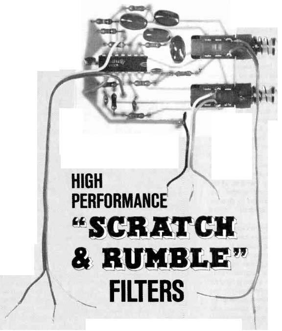
These filters are designed around a quad BIFET operational amplifier IC, and can be inserted into or removed from the signal chain at the push of a switch. The project can be built at low cost, and its compact size allows it to be tucked into an existing audio component. Also, its modest power requirements can easily be satisfied by the host component.
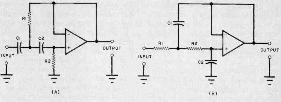
About the Filters. One of the simplest active filter designs is based on the volt age-controlled voltage source configuration. This circuit is commonly known as the Sallen /Key design because it was described in a paper by R.P. Sallen and E.L. Key that appeared in the March 1955 issue of the IRE Transactions on Circuit Theory. Shown schematically in Fig. 1 are second-order, high-pass (A) and low-pass (B) active filters employing operational amplifiers. Although op amps as we know them were not avail able in 1955, Sallen and Key's paper is applicable to filters employing more recently developed active devices.
These filters have unity gain within their passbands, a gain that is independent of resistor values. They have second-order responses, which exhibit an attenuation of 3 dB at the cutoff frequency and an ultimate slope of 12 dB/ octave. For audio applications, the most useful VCVS filter is one whose response is "maximally flat," whose 0 is 0.707. This is true of the filters described in this article.
The cutoff (-3-dB) frequency of the high- or low-pass filter can be calculated from
fc = 1 /[2 pi (R1 R2 C1 C2)^1/2].
In the high-pass filter of Fig. 1A, the value of C1 is chosen to equal that of C2 and the resistance of R1 is chosen to be half that of R2. This simplifies the equation for the cutoff frequency so that it takes the form:
fc = 1/ 2.828 pi C1 R1.
Similarly, in the low-pass filter of Fig. 1B, the resistance of R / is chosen to equal that of R2 and the capacitance of C2 is chosen to be half that of C1. The simplified equation for the low-pass cutoff frequency is:
fc = 1/ 2.828 pi R2C2.
Note that the low-pass filter resembles the high-pass design except that the positions of the resistors and capacitors have been interchanged.
If optimal filter performance is to be achieved, the passive components used should be of high quality. For example, the resistors should be carbon- or metal-film components and the capacitors should have mica, polystyrene or Mylar dielectrics. The criteria for choosing the operational amplifier are those that make an op amp well suited for use as a voltage follower-high input impedance, low input current, and high speed. The author's choice is the Texas Instruments TL074CN, a quad BIFET op amp that satisfies these requirements handily.
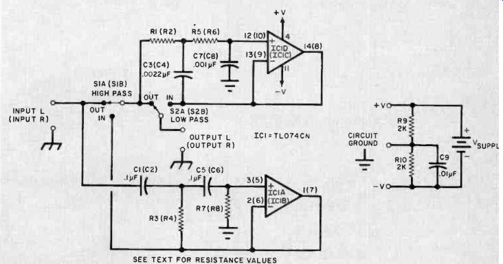
The complete schematic of the project is shown in Fig. 2. In all, four filters appear in this diagram-a low-pass and a high-pass filter for each stereo channel. The component designations not shown in parentheses pertain to the left-channel circuit. Those component numbers given parenthetically pertain to the right-channel filters.
If both selector switches (S / and S2) are in their our positions, the filter out puts are left floating. Placing HIGH PASS selector switch S / in its IN position connects the outputs of the high-pass filters (1C1A, 1C1B and their associated components) to the OUT positions of LOW PASS selector switch S2 and to the inputs of the low-pass filters (IC1C, IC1D and their associated components).
If S2 is in its IN position, signals pass through the low-pass filters before they appear at the project's output. Other wise, they are routed to the output terminals without being high-pass filtered.
This switching arrangement allows the connection of either filter alone, both together, or neither in the signal chain.
The circuit can be powered by either a bipolar or single-ended supply. Maxi mum voltages are ± 15 volts for a bipolar supply and +30 volts for a single-ended one. Current demand is approximately 10 mA. Components C9, R9, and R10 are required only if a single-ended power supply is used. They generate an artificial "circuit ground" which is designated in Fig. 2 using the conventional chassis-ground symbol. Contrast this with the system signal ground appearing at the input and output terminals of the project. An earth-ground symbol signifies system signal ground to differentiate it from the artificial "circuit ground." A single-ended supply is represented to the right of the passive components as a battery generating voltage V supply.
Traditionally, the chassis on which a positive, single-ended power supply is mounted becomes the negative return and is also used as the signal ground for the circuit powered by the supply. In the case of these active filters powered by a single-ended supply, the chassis can be used as the input and output signal ground (which will be tied to system ground), but the artificial ground generated by the passive components must be kept isolated from it. The artificial ground will be at a dc level equal to one half of the supply voltage, and the chassis (system) ground will act as the-V negative supply for the quad op amp.
If a bipolar supply is used, the artificial and system grounds should be tied together. Direct coupling can be employed between the stage preceding the filters and the project input terminals as well as between the project output terminals and the input of the next stage in the signal chain. However, if the circuit is powered by a single-end supply, capacitive coupling should be used.

Fig. 1. Second-order high-pass (A) and low-pass (B) filters.

Fig. 2. Schematic diagram of the complete project.
------------
PARTS LIST
C1 ,C2,C5,C6-0.1-µF 5% Mylar, mica or polystyrene C3,C4-0.0022-µF 5% Mylar, mica or polystyrene C7,C8-0.001-µF 5% Mylar, mica or poly styrene C9*-0.01-µF Mylar, disc ceramic, mica or polystyrene IC1-TL074CN quad BIFET op amp The following are carbon-film, 1/4-watt, 5%-tolerance (or metal film, 1/4- or 1/8-watt, 1% tolerance) fixed resistors unless otherwise specified.
R1 , R2, R5, R6-see text for value.
R3, R4-see text for value.
R7,R8-see text for value.
R9*,R10*-2000 ohms, 1/2-watt, 5% or 10% tolerance, carbon-composition or carbon film.
S1, S2-Dpdt switch
Misc.-Printed circuit or perforated board, IC socket or Molex Soldercons, suitable power supply and enclosure, hookup wire, shielded cable, circuit board standoffs, hardware, solder, etc.
* These components are required only if a single-ended power supply is used.
NOTE--The following are available from Phoenix Systems. 91 Elm St., Manchester, CT 06040: kit of parts including printed circuit board, IC; switches, and resistors and capacitors for two 20- or 50-Hz high-pass and two 13,000- or 19,000-Hz low-pass filters, No. P-91S for $15.00. Also available separately are; TL074CN quad BIFET op amp IC, No. P-91C for $2.50; etched and drilled printed circuit board, No. P-91B, for $5.00; push-on/push-off dpdt switch, No. P 91SW, for $1.00 each. Connecticut residents. add 7% state sales tax. If order is less than $10.00. add $1.00 shipping and handling.
-------------------------
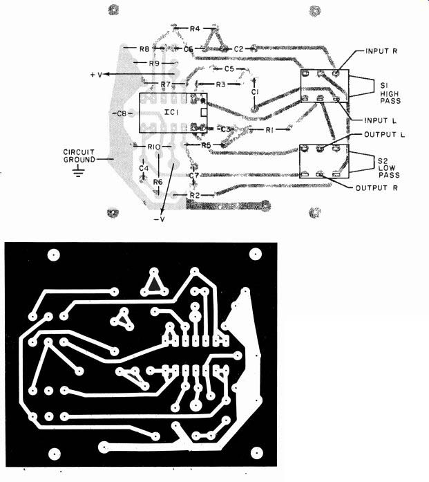
Construction. The project is relatively simple, so point-to-point, wiring, wrapped-wire, or printed-circuit assembly techniques can be used. Etching and drilling and parts placement guides for a suitable printed circuit board are shown in Fig. 3. If another assembly method is chosen, observe sound construction practices for circuits containing high gain-bandwidth devices. Keep leads short and run grounds carefully.
The use of Molex Soldercons or an IC socket is recommended. Be sure to orient the IC correctly and pay attention to polarities when making connections to the power supply. Use the minimum amount of heat and solder consistent with the formation of good connections.
The circuit board has been laid out to accommodate pc-mount push / push switches. These switches are available from the source given at the end of the Parts List. If you want to employ another type of switch, simply interconnect the foil pads with the appropriate lugs of the remotely mounted switches with lengths of flexible hookup wire.
Mount the filter board either in the enclosure of a host audio component or in an enclosure specially selected for this purpose. The board should be installed in such a way that board-mounted switches (if used) are readily accessible. If the project is placed inside an existing audio component, the simplest way to satisfy the project's modest power requirements is to tap the host's supply. A high-voltage supply can be used to power the project by introducing zener voltage regulation.
You will note that the values of all of the RC components in the active filters have not been specified in the schematic or the Parts List. This has been done to allow you to choose the cutoff frequencies of the filters that you assemble. The design equations for the low-and high-pass filters were given earlier.
In the high-pass design, use equal values of capacitance (0.1 µF) for C1, C5, C2, and C6. Select the resistance of R2 so that it is double that of R1. The value of FT1 can be calculated using the high pass design equation. In the low-pass filters, use equal values of resistance for R1, R5, R2, and R6. The capacitance of C7 and C8 should be half that of C3 and C4. Recommended values are 0.0022µF for C3 and C4 and 0.001µF for C7 and C8. Resistance values for any desired cutoff frequency can be calculated using the low-pass design data.
The most common application for the high-pass filter is to attenuate low-frequency turntable rumble. To be an effective rumble filter, the circuit should attenuate the low-frequency rumble without significantly altering the spectral power density of the program material. Most musical recordings contain little information in the bottom bass octave, so 50 Hz is an acceptable cutoff frequency. Component values that will produce a 50-Hz,-3-dB frequency are: C1, C5, C2, C6--0.1 µF; R3, R4--22,000 ohms; R7, R8 47,000 ohms. Those readers who want any deep bass present in their recordings to come through un-attenuated will prefer a lower cutoff frequency. Component values that will result in a cutoff frequency of 20 Hz are: C 1, C5, C2, C6-0.1 µF; R3, R4-56,000 ohms; R7, R8-110,000 ohms. For a cutoff frequency other than the two just given, calculate new resistance values.
Low-pass filters are frequently employed to attenuate FM hiss and disc surface noise. They are also useful to attenuate 19,000-Hz FM stereo subcarriers that can interfere with the taping of broadcasts off the air. To be an effective hiss or subcarrier filter, the circuit should attenuate high-frequency noise, etc., without the loss of program content at lower frequencies. Most musical pro gram material contains little information in the extreme highs, so 13,000 Hz is an acceptable cutoff frequency. Component values that will produce this response are: R1, R5, R2, R6-8200 ohms; C3, C4--0.0022 µF; C7, C8--0.001 µF. For a higher cutoff frequency, say, 19,000 Hz, use the following component values: R1, R5, R2, R6-5600 ohms; C3, C4-0.0022 µF; C7, C8--0.001 µF. If you prefer a cutoff frequency other than the two just given, calculate new resistance values.
Installation and Use. The project can be introduced into the audio system at any point where signals are at line level.
Two possibilities are at a tape monitor loop and between the preamp output and power amplifier input. It's good practice to insert a 51-ohm resistor between the "hot" output terminal of each channel's circuit and the inner conductor of the cable which carries signals to the input of the next stage. This can prevent oscillation due to the effects of cable or load capacitance.
In Conclusion. The active filters presented in this article offer a higher level of performance than those included in many audio components. A bit of experimentation will convince you how useful properly designed low- and high-pass audio filters really are.

Fig. 3. Full-size etching and drilling guide for printed-circuit board
is shown at above. Diagram for layout of components is shown in the top
diagram.
Source: (Popular Electronics Electronic Experimenter's Handbook (1983)
Also see:
Check Your Heat Loss With A Degree-Day Meter
Tools & Equipment for Electronic Workbenches