------
BY AL SYDNOR
How to use solid-state circuits to obtain predictable performance from electromechanical relays.
BECAUSE OF their simplicity and low cost, electromagnetic relays are widely used in control applications. Un fortunately, some experimenters and designers do not fully understand how to interface relays with electronic circuitry.
As a result, their circuits frequently operate erratically, and outright failure of either the relay or the components associated with it is far more common than necessary. Moreover, many possible functions that relays can perform with appropriate drive circuitry are often overlooked. A knowledgeable approach, such as that presented here, should enable one to use relays with confidence and without hesitation.
What is a Relay. An electromagnetic relay, regardless of details of construction, is basically a mechanical switch operated by electric power. Its contacts are coupled to an armature of magnetic material held in proximity to a coil. When current passes through the coil, the resulting magnetic field attracts the armature toward the coil to close or open one or more sets of contacts.
When the current stops, the magnetic attraction ceases, and a spring returns the contacts to their former positions.
Available in both ac and dc versions, relays have rated coil energizing potentials usually ranging from 1 to 250 volts with 6-, 12-, 24-, 48-, 117-, and 240-volt designs the most common.
There are also relays that operate at energizing potentials as low as 25 millivolts for special applications. You should keep the voltages within ±20% of ratings. Too much voltage may burn out the coil; too little may cause erratic operation. Operating power ranges from a few milliwatts to about 20 watts, which should be borne in mind when you are designing the drive circuits. Operating current can be determined by measuring or looking up coil resistance.
Looked at from the point of view of the drive circuit, a relay has the following parameters:
Operating voltage (current). The value that closes the contacts reliably.
Pull-in voltage (current). The value that just barely closes (opens) the contacts.
Drop-out voltage (current). The value that barely lets the contacts open (close).
The limits on current or voltage the relay can switch are also important.
Contacts are commonly rated either according to current capacity or by a maximum number of volt-amperes (VA), the product of current and voltage. If a relay that must handle heavy current cannot be driven from a low-power circuit, it can, in turn, be driven by a relay the circuit can handle.
Contact Protection. When a switch in series with an inductive circuit (such as a relay coil) is opened, the magnetic field in the coil collapses and a voltage proportional to the rate of change of current is generated. This high voltage across the switch contacts can eventually cause damage or failure.
Semiconductors can be used to sup press these voltage transients, as in Fig. 1A, where a diode is connected across the load as shown. When a positive spike appears across the switch contacts, the diode clamps it to the positive power-supply voltage. The diode's reverse-voltage rating must exceed the power-supply voltage, and its current rating must be at least 25 times the load operating current. A varistor, or voltage-dependent resistor, can be substituted for the diode. Its resistance should be more than 10 times the dc resistance of the coil at 20°C.
Sometimes, when a relay coil appears to have shorted for no reason, an inductive spike that exceeds its insulation ratings may be at fault. A diode can be used as in Fig. 1B to protect a relay coil if a longer release time can be tolerated. An improvement over this method is to use a transistor circuit as in Fig. 1C. When the switch in Fig. 1C is closed, the capacitor discharges. Opening the switch causes the capacitor to keep the transistor conducting until the capacitor has charged up through the base-emitter junction and resistor enough to cut off the transistor. This is equivalent to opening the switch slowly to lengthen the decay rate of the current and keep the induced voltage smaller.
Linear-Amplifier Driver. To drive high-current relays from low-current sources you can use a transistor amplifier such as that shown in Fig. 2A.
When S1 is set to OFF (ground), no base current is supplied, the transistor is cut off, and the relay is deenergized. Setting S 1 to its ON position sends the transistor into saturation and energizes the relay.
More sensitivity can be had simply by adding amplifier stages, as shown in Fig. 2B. If no input is applied to Q 1, it is cut off and Q2 is saturated energizing the relay. Application of bias to Q1 saturates it, and Q2 cuts off, deenergizing the relay.
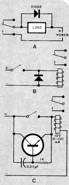
Fig. 1. Switching-transient suppression: diode across inductive load
(A) or relay coil (B); transistor circuit across switch contacts (C).
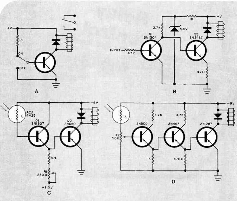
Fig. 2. Linear amplifiers as relay drivers: (A) single-stage; (B)
two-stage inverting; (C) two-stage noninverting; (D) three-stage noninverting.
Another two-stage transistor relay driver is shown in Fig. 2C. In this case, the circuit is noninverting and is con trolled by a photocell. The photocell controls Q1, which in turn controls Q2, whose collector current energizes the relay. The potentiometer permits adjustment of threshold voltage for the particular photocell being used and prevents leakage current from operating the relay under high-temperature conditions.
A single-power-supply, three-stage driving amplifier is shown in Fig. 2D.
Once again, illuminating the photocell energizes the relay, with the potentiometer permitting adjustment of the re lay's operating threshold. In the off state, all transistors are cut off and current consumption is negligible, which makes this circuit suitable for operation from a battery.
Regenerative-Amplifier Driver. The relay drivers discussed above have a serious disadvantage in that a border line threshold input can cause the relay to alternate rapidly between on and off, producing "chatter." Also, the energizing threshold can vary with temperature.
A regenerative amplifier can be used to keep the relay energized or deenergized with no in-between state.
A Schmitt trigger with a relay coil as the load is shown in Fig. 3A. As long as the input level is less than 6 volts, Q1 is cut off, Q2 is saturated, and the relay is energized. When the input exceeds 6 volts, Q1 rapidly saturates and cuts off Q2 to positively deenergize the relay.
The potentiometer permits precise set ting of the operating threshold.
Another regenerative-amplifier circuit is shown in Fig. 3B. Here, the relay's coil is the load for one side of an Eccles Jordan bistable multivibrator. This is a conventional design except for C1 and R1, which are used to ensure that Q1 will be driven into saturation and Q2 will be cut off when power is first turned on to prevent the relay from energizing on power-up.
A positive signal on the RESET line to the base of 02 activates the relay solidly, while a positive signal on the SET line to the base of Q1 deactivates the relay just as solidly.
Fig. 3. Relay-driver regenerative amplifiers: (A) single-stage Schmitt trigger; (B) single-stage bistable; (C) Schmitt trigger with relay driver; (D) latching SCR control.
When using high-power relays, it is usually necessary to add a buffer stage between the relay and regenerative circuit. A typical arrangement is illustrated in Fig. 3C. Here, Schmitt trigger Q11 Q2 is coupled to Q3 via 12-volt zener diode D1. When a negative control signal of sufficient amplitude is applied to the input of this circuit, Q1 conducts and Q2 cuts off. Current through the Q2 collector load resistor and D1 to the base of Q3 causes it to conduct and energize the relay.
Because 03's bottom potential at 1.5 amperes is less than 0.5 volt and this transistor's rated free-air dissipation is less than 1 watt, Q3 can be operated without a heat sink. If Q3 is to be operated at high ambient temperatures, however, it should be mounted on a 2" (50.8-mm) square sheet of No. 16 aluminum.
A regenerative relay driver that uses an SCR is shown in Fig. 3D. Initially, S1 and S2 are both open and no trigger voltage is applied to the gate of the SCR, which remains cut off. Closing S/ applies a positive voltage to the SCR's gate, triggering the SCR and energizing the relay.
Opening Si does not turn off the SCR.
It does, however, allow the voltage across capacitor C1 to approach that of the supply. Then, closing S2 applies a negative pulse to the anode of the SCR to stop conduction. An alternative to using S2 to turn off the SCR is to connect a transistor from the anode to the cathode, as shown by the phantom circuit in Fig. 3D. When the transistor turns on, it diverts current from the SCR. As soon as the SCR's current falls below its holding value, the device turns off. The relay coil is deenergized when the voltage to the base of the transistor is removed.
Time-Delay Circuits. Semiconductors are commonly used to provide time-delay periods for operating electromagnetic relays. An example of this is the delayed application of supply voltage to the power stages in a hi-fi amplifier to prevent the power-on transient from being heard in and possibly damaging the speaker systems. One simple way to delay energizing a relay is to place a thermistor in series with the coil, as shown in Fig. 4A. When the switch is closed, current flowing through the thermistor causes it to heat up, resulting in a decrease in resistance from its normally high cold resistance. As resistance drops, more current flows until the current through the relay coil is sufficient for energization. A series potentiometer can be used to permit adjustment of delay time.
At room temperature, the thermistor should have a resistance three to five times that of the relay's dc coil. For example, a thermistor with a cold resistance of about 400 ohms that drops to 25 ohms at 400 mA can be used with a conventional 12-volt, 80-mA relay.
The circuit in Fig. 4A is for slow energization and fast deenergization.
For applications where fast turn-on and a slightly delayed turn-off are required, a shunt thermistor can be used, as illustrated in Fig. 4B. Again, the thermistor's cold resistance should be 3 to 5 times the relay's dc coil resistance.
Another circuit that gives slow turn-on and fast turn-off relay operation is shown in Fig. 4C. When Si is closed, the base of the transistor is grounded and Q1 is cut off, resulting in a deenergized relay.
Opening S1 allows C1 to be charged at a rate determined by the C1 (R1 + R2) time constant until the base potential of Q1 is sufficient to turn on the transistor and energize the relay. Closing S1 causes C1 to discharge rapidly and cut off Q1 practically at once.
A rearrangement of the Fig. 4C circuit, shown in Fig. 4D, gives a fast turn-on and slow turn-off action. With the switch closed, the capacitor discharges and base current through the resistors from the supply line sends the transistor into saturation and rapidly energizes the relay. Reopening 51 allows the capacitor to continue to supply base current until it is charged up enough to cut off the transistor. The result is a slow turn-off for the relay.
Many variations of the above circuits are possible, such as the very slow turn-on circuit shown in Fig. 4E. With S1 open, all capacitors are discharged.
Closing Si allows C1 to be charged up via R1 until the voltage on the gate of Q1 rises above firing potential. At this time, 01 becomes a low resistance and applies a firing pulse to the gate of the SCR, which energizes the relay.
When S1 is opened, supply voltage is removed, the SCR stops conducting, and the relay deenergizes. This circuit has been used to provide a 40-second ( ± 1 second) delay over a-25° to +75°C temperature range.
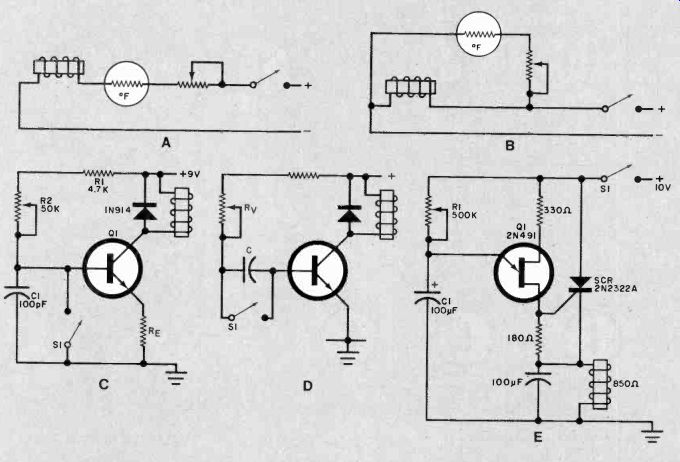
Fig. 4. Relay time-delay circuits. (A) thermistor-controlled slow-on/fast-off
(B) thermistor fast-on/slow-off; (C) transistor-controlled slow-on/fast-off.
(D) transistor fast-on/slow-off (E) unijunction transistor circuit
with very slow on.
Differential Drivers. Many of the relay-driver circuits shown above are limited by the fact that control-signal operation is uncertain and may have considerable backlash. (The relay may not deenergize until the voltage across its coil is well below the energizing potential.) One way to obtain close differential operation with the deenergizing and energizing voltages roughly equal is to use a Schmitt-trigger circuit with a small hysteresis (backlash), such as shown in Figs. 3A and 3C. Simply replace the common-emitter resistor of the Schmitt trigger with a zener diode whose voltage rating is the same as the potential required at the emitters to energize the relay.
As the input to the close-differential circuit shown in Fig. 5A is increased in the negative direction, no base current flows through Q1 until VIN exceeds the 10-volt breakdown potential of the zener diode plus the base-emitter forward voltage drop required for Q1 to conduct (about 0.3 to 0.5 volt). When VIN reaches about 11 volts, Q1 saturates and collector current energizes the relay.
The silicon diode across the base-emitter junction of Q1 prevents it from being overdriven. With up to 0.6 volt on the transistor's base, the diode does not conduct. Beyond this point, it conducts and shunts excess current away from the transistor's base. Because of the sharp breakdown characteristics of the zener diode, drop-out signal potential of this circuit is within a few hundred millivolts of relay energizing voltage.
Use of a p-channel MOSFET with a threshold potential of about 5 volts to yield close differential relay operation is shown in Fig. 5B. When VIN is greater than 6 volts, the zener diode conducts through R1, but as long as the input is less than 11 volts, the drop across R1 is less than 5 volts and Q1 is off.
As long as Q1 is cut off, Q2 is also cut off and the relay is deenergized. When the input exceeds 11 volts, Q1 conducts and current through R2 to Q2's base causes the relay to energize. When VIN is less than 11 volts, the relay is deenergized, while it energizes with positive action when VIN exceeds 12 volts. By cascading a second FET after the first, it is possible to reduce the difference between energizing and deenergizing potentials to 0.1 volt.
AC Drive Circuits. Any dc relay can be adapted to work from an ac source by combining it with rectifiers. In Fig. 6A, D1 permits only positive current to pass through the relay and should have a current-carrying capacity several times the operating current of the relay.
Clamping diode D2 is optional and is used for surge suppression. It not only protects the relay contacts, but pre vents high reverse voltage on D1.
Another diode arrangement is shown in Fig. 6B. Here, four diodes are used in a full-wave bridge circuit. Note that the bridge circuit inherently provides protection from inductive spikes.
The circuit in Fig. 6C allows a true ac relay to be operated electronically through an SCR. When S1 is open, the SCR has no potential applied to its gate and does not conduct. Meanwhile, cur rent from T1 is rectified by D1 and generates a dc voltage that is stored in C1. When S1 is closed, the positive voltage across C1 is applied to the gate, causing the SCR to conduct and remain on as long as S t is closed. Opening S1 causes the SCR to cut off when the ac cycle passes through zero, causing the relay to be deenergized.
Op Amp Relay Drivers. Contingent on the type and level of the input signal, relay amplifiers can be built up with op amps whose extremely high (open-loop) gain is sufficient to allow operation with minute input levels. The op amp also allows for differential operation where an input signal can be compared with a known reference so that the relay pulls in (or drops out) only when the desired voltage differential exists.
In addition, the op amp, with its very high gain, can be used with reactive feedback to form filters that produce relay operation only at certain input frequencies (assuming an ac input). A phase-locked-loop (PLL) using a 567 for instance, can also be a frequency-sensitive driver for a relay amplifier.
Since many op amps do not have sufficient output current to drive a relay directly, a transistor power stage will often be required between the op amp and the relay.
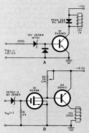
Fig. 5. Driver circuits with close differential operation: (A) single-stage
transistor with zener; (B) two-stage FET and bipolar transistor.
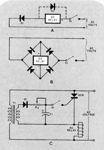
Fig. 6. Ac drive circuits: (A) single diode; (B) diode bridge; (C)
thyristor.
Source: (Popular Electronics Electronic Experimenter's Handbook (1983)
Also see:
Tools & Equipment for Electronic Workbenches