CD-i
The Compact Disc Interactive (CD-i) standard was devised as a product-specific application of the CD-ROM format.
CD-i permits storage of a simultaneous combination of audio, video, graphics, and text, and defines specific data formats for these. In addition, titles can function with real time interactivity. For example, a CD-i dictionary might contain a word and its definitions, as well as spoken pronunciation, pictures, and translations into foreign languages. The CD-i standard, codified in the Green Book (issued in 1986), defines how each type of information is encoded as well as logical layout of files on the disc. It also specifies how hardware reads discs and decodes information.
The CD-i data format is derived from the CD-ROM Mode 2 format. CD-i data is arranged in 2352-byte blocks, as in the CD-ROM/XA format. The CD-i format accepts either PCM or ADPCM (adaptive differential pulse-code modulation) data. The full-motion video (FMV) extension allows storage of 74 minutes of full-motion digital video and stereo audio. The MPEG-1 coding standard is used to reduce the video bit rate to 1.15 Mbps and the audio rate to 0.22 Mbps; lower rates can also be used. CD-i players can also play Video CDs coded with MPEG-1. MPEG-1 audio is described in Section 11 and MPEG-1 video in Section 16.
To ensure universal compatibility, dedicated hardware and interfaces are defined. The CD-Bridge format adds information to a CD-ROM/XA disc so it can be played on a CD-i player. Bridge tracks use Mode 2 data, tracks are listed in the TOC as a CD-ROM/XA track, and block layout is identical to CD-i and CD-ROM/XA. The Photo CD is an example of a Bridge disc. The CD-i format did not enjoy success among its targeted consumers.
Photo CD
The Photo CD is used to professionally store, manipulate, and display photographic images. Photographs can be viewed or reproduced as high-quality prints of images using a color printer. The 35-mm version of the Photo CD provides three to four times the resolution required in any high-definition television (HDTV) standard. Conventional photographic images can be scanned to the Photo CD, with 2048 scan lines across the short dimension of a 35 mm frame, with 3072 pixels on each line to yield a 3:2 aspect ratio. Data compression and decomposition are used to increase storage efficiency. During authoring, high resolution image files are subjected to a 4:1 data reduction.
In addition, file sizes can be reduced without significant visual loss by using chroma sub-sampling to take advantage of limitations in human visual perception. The Photo CD was developed by Kodak and is defined in the Beige Book.
Photo CD discs conform to the Orange Book Part II standard and are physically identical to CD-R audio discs; however, different data headers make them incompatible.
Data blocks are written according to the CD-ROM/XA, Mode 2, Form 1 standard. Because discs use the CD Bridge format, they are playable on CD-ROM/XA players.
Because the Orange Book Part II permits additional multisession recording to a disc, images can be added over time. Pacs initially recorded on a disc are structured as a file using the ISO 9660 structure. Subsequently recorded Pacs use a CD-R Volume and File Structures format, using the multisession method. All Pacs are addressed through the block-addressing method used by CD-ROM discs and defined by the ISO/IEC 10149 standard. Because the Photo CD adheres to the CD ROM/XA format, audio and video data can be interleaved; in this way, a soundtrack can accompany visuals. The Picture CD consumer format similarly stores photographic files on a CD-R disc; it provides 1024 × 1536 resolution using JPEG compression. The disc also contains software used to view and edit the photographs.
CD + G and CD + MIDI
The CD + G and CD + MIDI formats were devised to encode graphics or MIDI software on CDs, in addition to regular audio data. Special hardware or software is required to access this data. Eight subcode channels are accumulated over 98 frames; thus, each 98-bit subcode word is output at a 75-Hz rate. Subcode synchronization occupies the first two frames, thus a subcode block contains eight channels with 96 data bits. This data block is called a packet, and each quarter of a packet is called a pack. A pack is generated every 3.3 ms. Only P and Q are reserved for audio control information. Over the length of a CD, the remaining channels, R to W, provide about 25 Mbytes of 8-bit data. Utilization of that capacity has been promoted as CD + G or CD + Graphics, and CD + MIDI , sometimes known as CD + G/M. The player decodes the graphics or MIDI data separately from the audio data. In CD + G discs, data is collected over thousands of CD frames to form video images or other data fields. For example, a CD + G audio disc can contain video images, liner notes, librettos, or other information. Because video images require a large amount of data for storage, CD + G images provide limited resolution.
In the CD + MIDI application, MIDI (Musical Instrument Digital Interface) information is stored in the subcode field, and output synchronously with the audio playback. External MIDI instruments can synchronize to the melody or other musical parameters of an encoded disc. The subcode capacity is sufficient to store up to 16 channels of MIDI information. MIDI information can be supplemented with graphics information; for example, music notation could be supplied. Another variation can encode music notation in the subcode area to allow print out of sheet music. CD + G/M discs are compatible with any CD player, but only players equipped with CD + G/M output ports can retrieve the information from the disc. Alternatively, an external decoder can be connected to any CD player with a digital output port, provided that the full subcode data is available from the port. CD + G is sometimes used for karaoke applications.
CD-3
In addition to regular 120-mm-diameter CD discs, the CD 3 format describes 80-mm-diameter discs. The name derives from the approximately 3-in diameter. This small size promotes greater portability and the format is useful for short audio programs. A CD-3 disc holds a maximum of 20 minutes of music. Because a CD data track begins at the innermost radius, CD-3 discs are compatible with regular discs and players. Some players have concentric rings in their disc drawers to center both diameter discs over the spindle. The CD-3 format is also used to hold over 200 Mbytes of CD-ROM data. The CD-3 format is also used for CD-R and CD-RW discs.
Video CD
The Video CD format is an outgrowth of the CD-i standard; full-motion video was added to the original CD-i standard and that feature was subsequently revised in 1992 to form the Video CD standard. The Video CD uses the MPEG-1 coding standard for audio and video. The audio signal is coded with the Layer II standard at 44.1 kHz. A disc stores about 74 minutes of full-motion digital video and audio; a feature film is placed on two discs. The video decoder chip permits full-motion video (FMV) to be shown at either 29.97 (NTSC) or 25 (PAL/SECAM) frames per second at 352 pixels by 240 lines and 352 pixels by 288 lines, respectively, one-fourth the resolution of DVD's normal mode. The Video CD may be shown as a quarter-screen image. The video bit rate is 1.15 Mbps and the audio bit rate is 0.22 Mbps. The Video CD format is a CD-ROM/XA Bridge disc, Mode 2, Form 2; this allows a Video CD to play on a CD-ROM drive. A Video CD disc will not play on a CD-Audio player, but will play in many DVD players.
Video CD is described in the White Book; version 1.0 of this specification was originally developed in 1992 for karaoke discs and in 1995 it was extended to version 2.0, which supported interactive video. The Video CD is different from the CD-Video format, now abandoned. The MPEG-1 video algorithm is discussed in Section 16. MPEG 1 audio is discussed in Section 11.
The Super Video CD (SVCD) is an enhanced version of the Video CD designed primarily for higher-quality movie playback. SVCD uses MPEG-2 coding for video compression to store about 70 minutes on a disc. The NTSC resolution is 480 × 480, and PAL resolution is 470 × 576-about three-fourths that of DVD's normal mode. Dual mono, stereo or 5.1-channel soundtracks can be used at bit rates ranging from 32 kbps to 384 kbps using MPEG-1 Layer II or MPEG-2 multichannel codecs. Uncompressed audio cannot be stored. The maximum data rate is 2.2 Mbps by virtue of a 2 × drive. However, at the higher data rate, playback time is halved to about 35 minutes; a movie might occupy three discs. Copy Generation Management System (CGMS) copy protection can be enabled. SVCD's development was sponsored by the Chinese government as a low-cost alternative to DVD. Other technical aspects were derived from the Video CD format and the China Video CD (CVD). The SVCD specification was ratified by the China National Committee of Recording Standards in September 1998. SVCD is also standardized in the IEC 62107 document. A similar specification, the Chao-Ji ("Super") VCD standard, was developed to support both China Video CD and SVCD; many SVCD players and changers support the Chao-Ji standard and most discs use the SVCD format. The DSVCD (Double SVCD) format uses a smaller track pitch to permit longer high-quality playing times of about 60 minutes.
Super Audio CD
When the Compact Disc was launched in 1982, it was rightly heralded as a data carrier of immense storage capacity. However, over time the CD seemed increasingly small. Moreover, some audiophiles argued that its specifications constrained audio fidelity. In particular, the CD was insufficient for the large file sizes and high bit rates required by surround sound and high sampling frequency audio. In 1999, Philips and Sony introduced the high density Super Audio CD standard, known as SACD. The SACD format supports discrete-channel (two-channel and multichannel) audio recordings, using the proprietary one bit Direct Stream Digital (DSD) coding method. DSD uses a high sampling frequency and achieves a flat frequency response to 100 kHz and a dynamic range of 120 dB in the 0- to 20-kHz band.
SACD players can play both SACD and CD discs. SACD is not compatible with the DVD or Blu-ray formats.
The mechanical and optical properties of an SACD disc are similar to those of a DVD-5 disc; however, the logical layout of content, the data format, and the copy protection measures are different. DSD data is not playable in standard DVD or Blu-ray drives, but a CD layer, if present on an SACD disc, is playable. Some players may include decoders to accommodate multiple disc formats. Other data such as text and graphics (but not video) can be included on an SACD disc; this content follows the Blue Book "Enhanced CD" standard. The SACD standard is sometimes known as the Scarlet Book, published in March 1999.
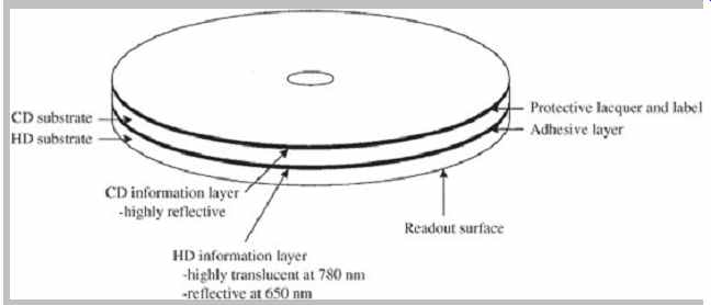
FIG. 31 A hybrid SACD disc contains two data layers (high-density and
CD). The two layers are bonded together to form a disc with a thickness of
1.2 mm. (Verbakel et al., 1998)
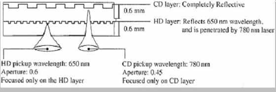
FIG. 32 Both the high-density layer and CD layer in a hybrid SACD are
read from one side by a laser. The high density layer is semi-reflective, while
the CD layer is fully reflective.
Disc Design
SACD discs use the same dimensions as a CD: 12-cm diameter and 1.2-mm thickness. The laser wavelength is 650 nm, the lens NA is 0.60, the minimum pit/land length is 0.40 µm, and the track pitch is 0.74 µm. (The pertinent CD figures are 780 nm, 0.45, 0.83 µm, and 1.6 µm.) Software providers may choose from three disc types specified in the SACD format: single-layer, dual-layer, and hybrid disc construction. The single-layer disc contains one layer of high-density DSD content (4.7 Gbytes); for two-channel stereo, this provides about 110 minutes of playing time.
The dual-layer disc contains two layers of high-density content (8.5 Gbytes total). The hybrid disc is a dual-layer disc that contains one layer of high-density DSD content (4.7 Gbytes) and one layer of Red Book compatible stereo content (680 Mbytes), as shown in FIG. 31. The semi reflective high-density layer must be reflective (readable) at the 650-nm wavelength of SACD, and transparent at the 780-nm wavelength used by conventional CD players; in other words, it acts as a color filter. The high-density layer is 0.6 mm from the readout surface and the CD layer is 1.2 mm from the surface. An SACD player can read both layers, and a CD player can read the CD layer.
In dual-layer discs, two 0.6-mm substrates are bonded together. In all implementations, there is only one data side.
A semi-reflective layer (20 to 40% reflective and approximately 0.05 µm in thickness) is used on the embedded inner data layer; in some cases, a silicon based dielectric film is used. A fully reflective top metal layer (at least 70% reflective and approximately 0.05 µm in thickness) is used on the outer data surface. This surface is protected by an acrylic layer (approximately 10 µm in thickness) and a printed label. Care must be taken to seal a hybrid disc to limit water absorption and evaporation from the substrate; unequal absorption between the two disc sides could cause disc warpage. The back side is inherently protected by a metal layer and a lacquer layer while the front side is nominally unprotected, thus a front side transparent silicon-based coating (10 nm to 15 nm) is needed. A hybrid disc in which a dual pickup (650 nm and 780 nm) is used to read both SACD and CD data is shown in FIG. 32.
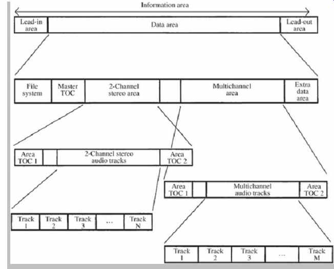
FIG. 33 The SACD high-density data layer is designed to carry both two-channel
and multichannel audio data.
The data on an SACD disc is grouped into sectors of 2064 bytes. This comprises: Identification Data (ID) of 4 bytes, ID Error Detection (IED) of 2 bytes, Reserved of 6 bytes, Main Data of 2048 bytes, and Error Detection Code (EDC) of 4 bytes. During encoding, following scrambling, 16 sectors form an error-correction code block, which is processed with a scheme using a Reed-Solomon Product Code. Rows of ECC blocks are interleaved and grouped into recording frames. Frames undergo EFMPlus modulation. Data is then placed in Physical Sectors and recorded to disc.
The radius of the high-density layer is segmented for different kinds of data, as shown in FIG. 33. The innermost radius contains the disc lead-in area, followed by the data area. It is divided into several areas including a Master Table of Contents (Master TOC) containing information on tracks and timing, as well as text data on the title and artist. The Master TOC is stored in three places (sectors 510, 520, and 530) to ensure readability. The next two radial areas are given to two-channel and multichannel recordings (up to six channels). The two-channel and multichannel areas use the same basic structure. The Area TOC for each audio area is placed at the beginning and end of each area. They contain track, sampling frequency, timing, and text information about the tracks included in that section. The SACD standard permits up to 255 tracks.
Audio tracks contain two types of streams: audio elementary stream and supplementary data elementary stream; they are multiplexed. In addition, there are sequences of audio frames each with a timecode, and supplementary data frames for pictures, text, and graphics; each frame represents 1/75 second. Following the audio tracks, there is an area for optional data such as text, graphics, and video. This data can only be accessed by a file system; its format is not specified in the SACD specification. The outermost radius holds the disc lead-out.
SACD discs can be read using a hierarchical TOC, or by optionally using a UDF or ISO 9660 file system.
FIG. 34 In principle, DSD coding is based on a one-bit quantization method. A. A one-bit quantizer produces a square wave output. B. The output square wave from a one bit quantizer yields a large difference signal.
All SACD discs incorporate an invisible watermark that is physically embedded in the substrate of the disc. Virtually impossible to copy, the watermark is used to conduct mutual authentication of the player and the disc. SACD players read the watermark and will reject any discs that do not bear an authentic watermark. Visible watermarks on the signal side of the disc in the form of faint images or letters may also be employed. A process called Pit Signal Processing (PSP) uses a controlled array of pit widths to create both invisible and visible watermarks; user data stored as pit/land lengths is unaffected by this watermarking.
DSD Modulation
Whereas all CD discs carry PCM data, all SACD discs carry Direct Stream Digital (DSD) data, in which audio signals are coded in one-bit pulse density form using sigma-delta modulation. Most conventional analog-to digital (A/D) converters use sigma-delta techniques in which the input signal is upsampled to a high sampling frequency. The signal is passed through a decimation filter and also quantized for output as a PCM signal at a nominal sampling frequency of 44.1 kHz (for CD) and up to 192 kHz (for DVD-Audio or Blu-ray). Likewise, many D/A converters use oversampling to increase the sampling frequency of the output signal, to move the image spectra from the audio band. As in PCM systems, DSD begins with a high sampling frequency, but unlike PCM systems, DSD does not require decimation filtering and PCM quantization in the recording process; instead, the original sampling frequency of 2.8224 MHz is retained. One-bit data is recorded directly on the disc. Unlike PCM, DSD does not employ interpolation (oversampling) filtering in the playback process. In other words, the basic DSD specification is based on the direct output of a typical sigma-delta A/D converter at 64 × 44.1 kHz.
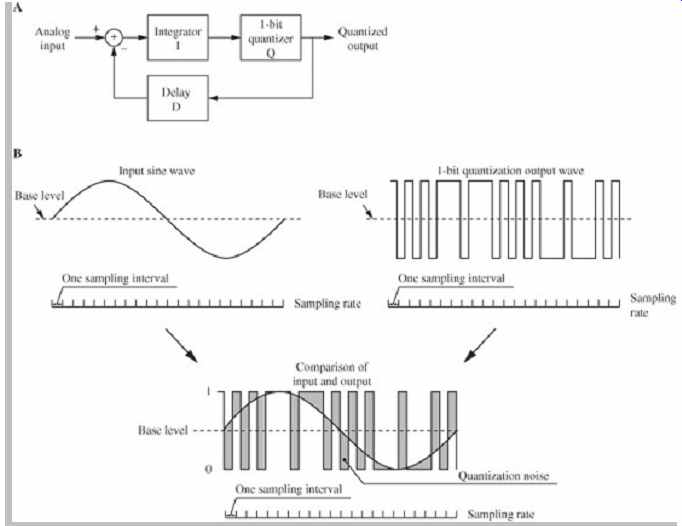
FIG. 35 DSD coding uses a sigma-delta coding technique. A. A sigma-delta
modulator uses negative feedback to subtract a compensation signal from the
input. B. The output signal from a sigma-delta modulator is a pulse-density
waveform.
DSD uses sigma-delta modulation and noise shaping. A simple one-bit quantizer is shown in FIG. 34A, and the output waveform resulting from a sine-wave input is shown in FIG. 34B. The shaded portion shows the difference error between the input waveform and the quantized output waveform. An example of a simple sigma-delta encoder is shown in FIG. 35A. The one-bit output signal is also used as an error signal and delayed by one sample and subtracted from the input analog signal. If the input waveform, accumulated over one sampling period, rises above the value accumulated in the negative feedback loop during previous samples, the converter outputs a 1 value.
Similarly, if the waveform falls relative to the accumulated value, a 0 value is output. Fully positive waveforms will generate all 1 values and fully negative waveforms will generate all 0 values. This method of returning output error data to the input signal to be subtracted as compensation data is called negative feedback.
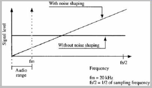
FIG. 36 Noise-shaping algorithms are designed to reduce the low-frequency
(in-band) quantization error, but also increase high-frequency (out-of-band)
content.
FIG. 35B shows an input sine wave applied to a sigma-delta encoder and the resulting output signal. The pulses of the output signal reflect the magnitude of the input signal; this is a pulse density modulation representation in which a 0 value has no pulse output while a 1 value does.
The shaded portion shows the difference error; analysis shows that the volume of error is the same as in a simple quantizer; however, because the integrator (sigma) in the sigma-delta encoder acts as a lowpass filter, the amount of low-frequency error is reduced while the amount of high frequency error is increased, as shown in FIG. 36. The system's designers note that the ear is sensitive to very high-frequency signals only if they are correlated to lower in-band signals. At frequencies higher than 20 kHz, they state that signal-to-noise ratios become less important.
Thus, they argue that the uncorrelated high-frequency shaped noise is perceptually unimportant. This noise shaping property can be developed with higher-order (perhaps 5th order) noise shaping feedback filters to further decrease error in the audible range of frequencies. In principle, a lowpass filter can decode sigma-delta signals.
Such a low-pass filter would also remove high-frequency noise resulting from noise shaping. The principles of sigma-delta modulation and noise shaping are discussed more fully in Section 18.
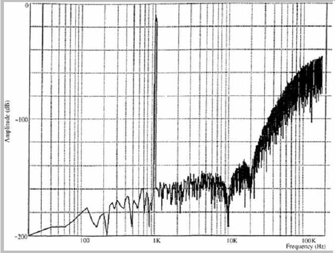
FIG. 37 DSD coding used in the SACD format requires significant noise
shaping to reduce low-frequency noise.
However, this significantly increases high-frequency noise above 20 kHz.
The DSD modulation used in the SACD format uses a sampling frequency that is 2.8224 MHz. In other words, the analog signal is sampled at a 2.8224 MHz rate and each sample is quantized as a one-bit word. Overall, the bit rate is thus four times higher than on a CD. In principle, the Nyquist frequency is thus 1.4112 MHz. However, in practice, to remove high-frequency noise introduced by high-order noise shaping, the high frequency response is limited to 100 kHz or less by analog filters. As shown in Fig. 37, a significant noise-shaping component is present in the 100-kHz band, as anticipated by the SACD standard.
The SACD standard specifies that noise power in the 100-kHz band should be 20 dB below the standard reference level. When a 100-kHz lowpass filter is used, at a volume level that achieves a 100-watt output, this noise component is thus 1 watt or less. However, at higher volume levels, the SACD standard recommends that SACD players incorporate a lowpass filter with a corner frequency of 50 kHz and a minimum 30-dB/octave slope for use with most conventional power amplifiers and speakers.
When making audio measurements of the SACD, a 20-kHz lowpass filter (such as the 3344A filter by NF Electronic Instruments with 60 dB of attenuation above 24.1 kHz) is recommended to avoid the effects of the shaped components in the higher frequency range.
The 2.8224 MHz (64 × 44.1 kHz) sampling frequency of the one-bit DSD signal can be converted to a variety of standard PCM sampling frequencies with integer computation. Division by 64 and 32 yields 44.1 and 88.2 kHz. Following multiplication by 5, division by 441, 294, and 147 yields 32, 48, and 96 kHz, respectively. Also, an extended sampling frequency of 128 × 44.1 kHz is possible.
DST Lossless Coding
A lossless coding algorithm known as Direct Stream Transfer (DST) is employed in the SACD format to more than double effective disc capacity. Eight DSD channels (six multichannel plus a stereo mix) on a 4.7-Gbyte data layer are allowed a playing time of 27 minutes, 45 seconds.
With DST, a 74-minute playing time is accommodated, effectively increasing storage capacity to about 12 Gbytes.
As with other lossless compression methods, the compression achieved by DCT depends on the audio signal itself. In one survey, DCT yielded a coding gain of 2.4 to 2.5 for pop music, and 2.6 to 2.7 for classical music.
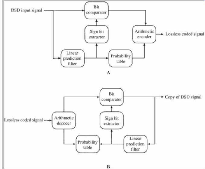
FIG. 38 Direct Stream Transfer (DST) can be used for lossless coding of
DSD data using an adaptive prediction filter and entropy (arithmetic) coding.
A. DST encoder. B. DST decoder.
The DST encoder and decoder are shown in FIG. 38.
DST uses data framing, an adaptive prediction filter and entropy coding. The use of lossless coding can be decided on a frame-by-frame basis; the flag information for the decoder is contained in each frame header. An area without any DST frames can be marked accordingly in the area TOC. DST coding yields variably sized frames; a buffer model is used to output a fixed bit rate. The theory of lossless coding is discussed in Section 10.
Player Design
SACD players play back both SACD and CD discs. Their design is similar to that of CD players. Dual laser pickups are required to operate at both the SACD 650-nm wavelength and the CD 780-nm wavelength. In some player designs, a single processor accepts the amplified RF signal from the dual pickup and performs clock signal extraction and synchronization, as well as demodulation and error correction for both CD and SACD signals. A servo chip controls the pickup and motor systems. CD data is passed along to the digital filter. SACD data is applied to the DSD decoder; this circuit first reads the invisible watermark, then intermittent data is rearranged and ordered in a buffer memory according to a master clock.
This chip also reads subcode data, including TOC information such as track number, time, and text data.
DSD data is output as a one-bit signal at a frequency of 2.8224 MHz and applied to a pulse-density modulation processor in which the data signal is converted to a complementary signal in which each 1 value creates a wide pulse and each 0 value creates a narrow pulse. A current pulse D/A converter converts the voltage pulse output into a current pulse. This current pulse signal is passed through an analog lowpass filter to create the analog audio waveform. In some designs, this filter's response measures -3 dB at 50 kHz.