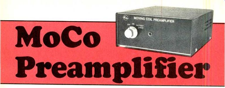
Super matched pair of low-noise transistors provides the needed audio boost for your super-fi, moving-coil phono cartridge.
by RON DE JONG
BY FAR THE MOST COMMON CARTRIDGE CURRENTLY IN USE IS the moving-magnet cartridge. In that design, a tiny magnet is mounted on the remote end of the cantilever and provides a magnetic field cut by two fixed coils mounted close by. When the magnet is set in motion, as occurs when the stylus tracks the record groove, the magnetic field moves and small electrical signals are generated by the two coils. Those signals are subsequently fed to a phono preamplifier and to the tone control and power amplifier stages.
Over the last few years, however, there has been renewed interest in another type of cartridge-the moving coil cartridge. Some dedicated hi-fi enthusiasts claim that the moving coil cartridge offers advantages in terms pf transient response, frequency response, and phase response at high frequencies. Whether or not those claims are valid is a matter for some argument- suffice to say that we do not intend to enter the debate here.
So how does a moving-coil cartridge differ from a moving-magnet type? The answer is that the positions of the coils and magnets are reversed, although the principle of operation remains essentially the same.
In the moving-coil cartridge, the magnet is held stationary while two miniature coils are mounted on the cantilever assembly and move as the stylus tracks the groove (hence the name "moving coil "). Since the coils are attached to the cantilever, they must be kept extremely small to keep the tip mass to a minimum. As a result, the output level of a moving-coil cartridge is extremely low, typically around 200 uV. That is around 27 dB below the output level of a moving- magnet cartridge, which is typically around 5 mV, or more.
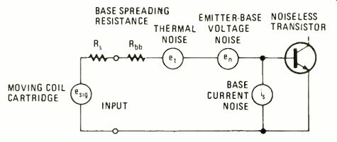
FIG. 1--SIMPLIFIED MODEL of a noisy transistor amplifier. The noise-generating
elements from the transistor which actually cannot exist. The text provides
detailed circuit description.
Because the output of a moving-coil cartridge is so low, considerable voltage gain is required before the signal is fed into the phono inputs of a conventional hi-fi amplifier. One solution is to use a transformer, but those are quite expensive and difficult to manufacture. The alternative solution is to use an additional preamplifier stage; and the design presented here has performance equal to or better than most commercial units for a fraction of the cost. We call it the MoCo Preamplifier for obvious reasons.
Before taking a look at the circuit, however, it may be as well to point out that the requirement for a separate preamplifier is one reason why moving-coil cartridges have not gained widespread popularity in the past. Commercial units tend to be expensive and that, coupled with the high cost of the cartridge itself ($100 or more), has been sufficient to deter most hi-fi enthusiasts. This project will help overcome that problem, as far as the cost of the preamplifier is concerned!
Design considerations
Perhaps the most important specification of a MoCo Preamplifier is the signal-to-noise ratio. Let's first take a look at the various sources of noise and find out how they may be minimized in a low-noise preamplifier design.
There are four main sources of noise in a transistor amplifier: shot noise, emitter-base voltage noise, 1/f noise, and thermal noise. Those individual noise sources are illustrated in Fig. 1, which shows a simplified model of a noisy transistor amplifier. Note that we only show noise generators at the input of the amplifier and not noise generated in later stages. In most cases that is quite valid, because the amplifier is most sensitive at the inputs and following stages will operate at higher signal levels.
Looking at each noise source individually: "Shot noise" or quantum noise occurs because of the discrete nature of electric current, which is actually pockets of individual electrons comprising the current flow and not a homogenous flow like water from a tap. The mechanism involved is analogous to rainfall in that individual raindrops striking a tin roof create noise. From that, you can see that shot noise actually increases with collector current. Another feature of shot noise is that it is "white" in character, that is the noise amplitude is constant with frequency.
Referred to the input of the transistor, the shot noise is called base-current noise and is modeled by a current generator at the input (see Fig. 1). Emitter-base voltage noise is modeled by a voltage source in series with the base. That is also a white-noise source but, unlike base-current noise, actually decreases with increasing collector current.
1/f or flicker noise is a significant source of noise at low frequencies because, as its name suggests, it has 1/f spectral characteristic and thus noise voltage increases as the inverse of the frequency.
The best-known source of noise is probably the thermal or Johnson noise generated in a resistor. That also has a white-noise distribution. We can minimize that source of noise by minimizing the input resistance, and that has the added benefit of reducing input-noise voltage due to base-noise current.
Referring to Fig. 1, we can see that the input resistance consists of the source resistance and the "base- spreading resistance" of the input transistor. The source resistance (Rs) is the resistance of the moving-coil cartridge, while the base-spreading (Rbb) resistance is an inherent feature of the transistor.
Clearly, we can significantly reduce thermal noise by choosing a transistor with a very low Rbb-or base-spreading resistance. Most audio transistors have an Rbb of around 100, while for some UHF transistors it can be as low as 4. In fact, some designs for moving-coil preamps do use UIF transistors. We can also achieve low Rbb, however, by simply connecting a large number of transistors in parallel, thus dividing Rbb by the number of transistors used.
The approach we eventually took was to use an LM344 super-matched transistor pair. Each of those transistors actually consists of a large number of individual transistors connected in parallel, giving each device an Rbb of 40 or 20 when the two are connected together. Those transistors also have very high Hfe of 500 and, due to the large number of transistors, statistical variations are considerably reduced; thus 1/f noise is very low.
What has emerged so far is that we can minimize noise by reducing the input resistance; but so far we have not considered how to minimize the effect of base-current noise and emitter-base voltage noise. Since one increases with collector current while the other decreases, there is an optimum collector current at which the overall noise is at a minimum. To work that out we have to sum all the noise sources into an equivalent input-noise voltage.
Since the various sources are statistically unrelated, we do not simply add the voltages together but take the square root of the sum of the squares. Differentiating that equation with respect to collector current reveals that the minimum noise can be calculated, and suggest suitable design considerations.
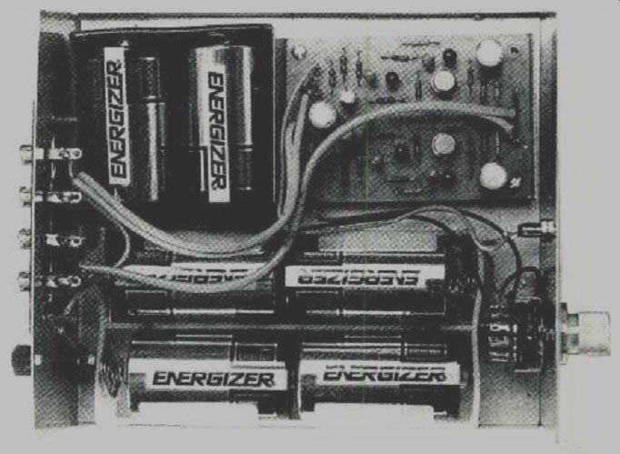
-------- GUTS-EYE VIEW of the MoCo preamplifier illustrates how neat
and clean this project can be assembled. Batteries take up the bulk of
the volume in the cabinet. Should you prefer a 12-volt regulated supply,
the outside case can be greatly reduced. Use shielded cables for input and
output leads to and from the printed circuit board. Use a wall-plug /battery
supply to feed the regulator circuit.
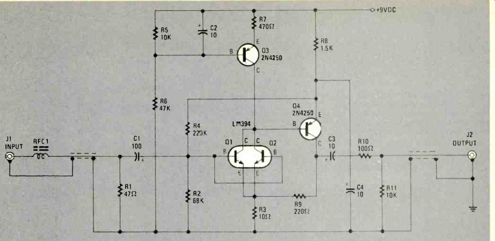
FIG. 2--ONE CHANNEL of the necessary two channels for the stereo amplification
of a moving-coil stereo cartridge. Each audio channel. except for the
common power supply and phono cartridge, is electrically apart and independent.
Transistors Q1 and Q2 are physically located in one metal too-hat can,
and appears as a single transistor in the unit should you not spot the six
leads coming from the. base.
-------------
PARTS LIST FOR MOCO PREAMP
(Note: double quantity for stereo)
SEMICONDUCTORS
Q1, Q2--LM394--Super- matched pair NPN transistor
Q3, Q4- 2N4250 or AET4250 low-level, low-noise silicon transistor
RESISTORS
All resisters are-watt 5% fixed composition type
R1-47-ohm
R2--68,0003-ohm
R3--13-ohm
R4--220 000-ohm
R5, R11--10,000-ohm
R6-- 47,000-ohm
R7--470-ohm
R8--1500-ohm
R9--220-ohm
CAPACITORS
All capacitors are 16- WVDC, electrolytic type
C1--100-uf
C2-C4—10uF
ADDITIONAL PARTS AND MATERIALS
J1, J1--Phono tack, RCA type
RFC1-4 turns of #28 wire on Phillips FX1115 ferrite bead
Metal case, printed circuit materials, hardware, wire, solder, etc.
PARTS LIST FOR BATTERY POWER SUPPLY
B1--6, 1.5-VDC D cells connected in series
C5--100-uF, 16-WVDC electrolytic capacitor
D1- 5.6-V. 400-mW Zener diode
LED1-Light emitting diode, red diffused lens
S1--Single-pole, 3-position toggle switch (center off); one throw position may be spring-return to off R12--200-ohm 1/4-watt, 5% resistor
Battery holders tor D cells, wire, hardware, etc.
-------------
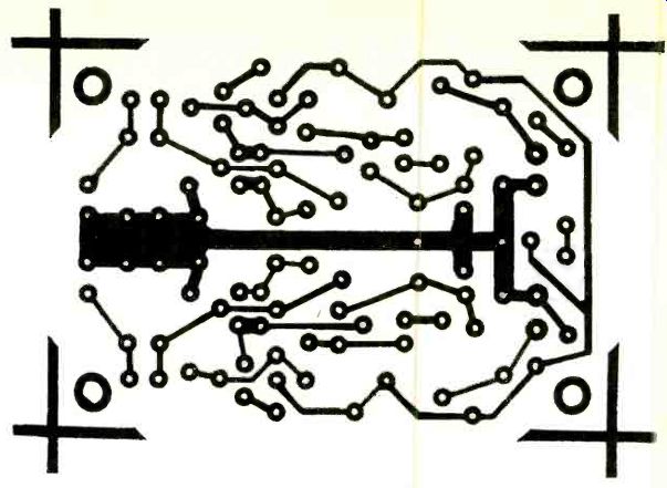
FIG. 3- FOIL-SIDE PATTERN of the printed-circuit board used to assemble
the MoCo Preamplifier. Physical isolation of the left and right audio stereo
circuits greatly reduces possibility of crosstalk.
The circuit
Let's now take a look at the actual circuit we have used. See Fig. 2. The basic configuration is one we have taken from the National Semiconductor Linear Applications Hand- book and uses just four transistors. Briefly, Q1 and Q2 are connected in parallel as a common-emitter amplifier, with Q3 as a constant current load. That drives Q4, another common-emitter amplifier, which in turn drives the output and the feedback network to Q1 and Q2.
Looking at the circuit in more detail now, we have included a small RF choke, RFC 1, at each input (you need two for stereo). It consists of four turns of No. 28 wire on an FX1115 bead and in conjunction with the 47-ohm resistor, R1 ,. following, prevents RF interference from being rectified by the input stage and passed to the amplifier Q4. A 100-µF electrolytic capacitor, C1, couples the input signal to transistors Q1 and Q2.
Because of feedback to the emitters of Q1 and Q2, the input impedance of the stage is quite high at around 35,000-ohms. The recommended load for most moving coil cartridges is merely stated as being greater than 10-ohms but if it is too high the leakage inductance of the cartridge will create unwanted bass boost. It is for that reason that we have included the 47-ohm resistor, RI, on the input. Incidentally, that resistance is the standard input impedance of most moving coil preamplifiers.
The collector load of Q1 /Q2 is transistor Q3, used here as a constant-current source delivering about 3 mA. We have used it in preference to a simple resistive load because it permits us to adjust the collector current of Q1/Q2 in- dependently of gain. In addition, it increases the open-loop gain and linearity of the amplifier to give very low distortion figures. and increases the supply rejection ration (important if the unit is to be run from a plug pack). Following Q1 and Q2 we have another common-emitter amplifier consisting of transistor Q4. The emitter is decoupled to ground rather than to the supply, which again improves the supply rejection, and the emitter voltage is used to bias Q1 and Q2 on. The arrangement is a variation on collector biasing, because the emitter voltage of Q4 tracks the collector voltage of Q1 and Q2. However, it has an advantage over conventional collector biasing in that there is no loading effect.
Collector load of Q4 is a 220-ohm resistor, R9, which forms part of a voltage- divider feedback circuit with the 10-ohm emitter resistor. R3, of Q1 /Q2. The voltage-divider ratio sets the closed loop gain at 23 (or about 27 dB) which is the gain required to bring moving-coil cartridge output levels up to normal phono-input levels.
Output from the MoCo Preamplifier is AC-coupled via a 10-µF tantalum capacitor, C3, and a 100-ohm resistor, R ID, with a 10,000-ohm pull-down resistor, R11, after the capacitor to remove any DC voltage on the output. The purpose of the 100-ohm resistor is to isolate the feedback loop from any loading effects of the following amplifier or shielded cable.
If that is not done, any capacitive loading will introduce an additional phase lag which could make the MoCo Preamplifier unstable.
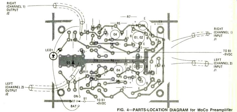
--------FIG. 4- PARTS-LOCATION DIAGRAM for MoCo Preamplifier shows how
simple the project really is. Note that there are many parts designations
that are repeated because both audio circuits use the same parts-symbol
designation technique. Those parts not duplicated on the printed-circuit
board relate to the power supply battery-check circuit in Fig. 2.
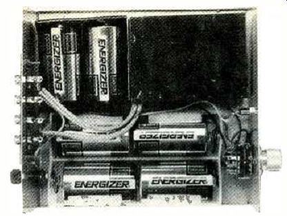
------- THIS INSIDE VIEW is slightly different from the other photo
because of the addition of a metallic shield within the metal case. The
added shielding will greatly reduce noise pickup, a common fault with many
low-level, high-gain preamplifiers.
The computed equivalent input-noise voltage is 98 nV. That gives a S/N ratio of 64 dB with respect to a 150 uV input signal. This was exactly the measured result on the finished prototype.
One point which also emerges is that the base-noise current is well below the other noise sources. Hence, we could have increased the collector current of Q1 /Q2 and thus reduced the emitter-base voltage noise considerably. If we use the formula for optimum collector current for lowest noise we find that the current is around 20 mA which is much greater than the 3 mA we chose. We did that for two reasons however: lower distortion and lower power consumption.
Power for the unit is obtained from six 1.5-volt "D" size batteries (See Fig. 2). A battery check function is provided consisting of a front-panel light- emitting diode, LEDI, 220-ohm resistor. R12, and 5.6-V Zener diode, Dl. When the front panel switch, S1, is set to BATTERY CHECK, power is applied to the circuit. If the battery voltage exceeds the 5.6-V drop across the Zener and the 1.6-V drop across LED 1 (7.2 VDC) then LED 1 will turn on. If LED 1 glows very feebly or not at all, a new battery is required.
Construction
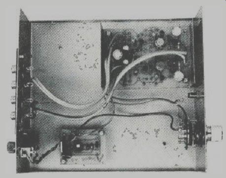
Construction of the unit is straightforward. Most of the components are mounted on a single printed- circuit board (Fig. 3 and 4). The author's unit was built into a standard metal case measuring 7 1/4 x 2 3/4 x 6 3/8 inches (D x H x W). The unit comes with a U-shaped steel cover and an aluminum base and, because the case is not all steel, trouble with hum fields from nearby power transformers may be experienced in some instances. Our solution was to mount the MoCo Preamp board inside a separate, small galvanized (more commonly referred to as galvanized iron) steel box. That gives excellent results and, because it is inside the main case, does not detract from the appearance of the unit. You will have to fabricate the steel box yourself if you cannot find some suitable steel box.
The PC board is mounted inside the box using four 3/8 to 1/2-in tapped brass spacers. Before mounting the PC board, however, make a cutout on the back panel for the 4-way RCA connector and drill holes and the back-panel earthing terminal and the front-panel switch and LED bezel.
The back-panel ground terminal must be connected to ground lug and there to the ground terminal on one of the output sockets. The RF chokes at the inputs are made by passing four turns of No. 28 enameled copper wire through a small ferrite bead, type FX l 115 from Philips. One end of each choke is soldered to an RCA input terminal and the other end to the inner conductor at the shielded cable. The outputs from the MoCo Preamplifier are also connected via shielded cable.
If you are using batteries to power your unit, then you will require one 4 x "D" cell battery holder and one 2 x "D" cell battery holder. They are wired up in series to give the requisite 9 VDC. Alternatively, a plug-pack power supply and the regulator board can be used.
Finally, check all wiring carefully and then switch to the "battery- check" position. The front-panel LED should come on to indicate that battery voltage is present. Now switch to the ON position and check the preamplifier for correct operation, simply by connecting it to a moving-coil cartridge and amplifier and trying it out. Happy listening!
ADDING A REGULATED SUPPLY
You may decide to power the MoCo Preamplifier with a regulated DC power supply to avoid the replacement of D cells from time to time. The suggested technique is to use an external 9-volt DC plug pack (a 12-volt unit will do) and then regulate the voltage to 9-volts. It can be done because the plug packs produce voltage as high as 20-volts DC with no load or very little load as is the case with the MoCo Preamplifier.
Use whatever regulated power supply you wish. The LM317 IC chip can do the job. Do not mount the plug pack inside the preamplifier case, or keep it close to the case, because the internal transformer will introduce considerable AC hum. With the batteries and holders removed, there is more than enough room in the chassis box. Regulated power supply circuits are easy to come by just flip the pages of this issue.
= = = =
Radio-Electronics--Special Projects (USA print magazine)
Also see: Phono Pickup Amplifier Design (part 1)--(Electronics Today magazine, Jan. 1982)