GOOD CONSTRUCTION is important to the satisfactory operation of any circuit. Knowledge of soldering and chassis-wiring techniques and of component-handling and safety precautions is as important to satisfactory circuit operation as is a knowledge of the electrical characteristics of a circuit. This section contains the mechanical information needed by the circuit builder; it should be read thoroughly before work on any circuit is started. A great deal of time and effort can be saved by planning a job thoroughly before beginning construction.
CONSTRUCTION PRACTICES
All of the circuits in this manual can be constructed with hand tools of the type available through any radio supply, mail-order retail, or hardware store. The greater the variety of tools on hand, the simpler the construction job will be; however, all required work can be accomplished with the basic set of tools listed in Table II. The continuing satisfactory performance of tools depends on the care they are given. Drills should be sharpened at frequent intervals so that critical cutting angles are maintained. Particular care should be taken of the soldering iron. The iron should not be Table II.
Tools Required for Circuit Construction
Awl or scriber for marking chassis Long-nose pliers, 6-inch Diagonal cutters, 6-inch Wire stripper Screwdrivers, 6 to 7 inch, 1/4-inch blade Screwdrivers, 4 to 5 inch, 1/8-inch blade Electric hand drill, 1/4-inch or larger chuck, variable speed type is best.
Electric soldering iron, 45 watts, 1/4-inch tip Center punch for marking hole centers Straightedge Files: assortment of flat, round, half-round, and triangular including one large, flat, coarse file and one 1/2-inch-diameter round file.
Drills: assortment including Nos. 32 (0.116 inch diameter), 58 (0.042 inch diameter), and 60 (0.040 inch diameter). Solder, rosin-core.
Additional Helpful Tools:
Bench vise, 4-inch jaws
Taper reamers, 1/2 and 1 inch
Phillips screwdriver
Screw-driver with screw-holding clip and long shank
Nut drivers run at full voltage for extended periods when it is not being used; if it is abused in this way, burn-out and tip corrosion can result. For stand-by purposes voltage to the iron can be reduced sufficiently by connecting an incandescent lamp in series with it. The tip of an iron that is not pre-plated should be cleaned with steel wool after each period of use and should be kept well tinned (coated with solder). A pitted tip should be filed smooth and bright and should be re-tinned immediately. Pre-plated tips should not be filed; they can be cleaned after each use with a wet sponge.
Materials
A list of materials required for the construction of each circuit is given with the circuit schematic. Only rosin core solder should be used in making connections; acid-core solder intended for plumbing and sheet-metal work is not suitable for circuit wiring.
Chassis Preparation
The building of an electronic circuit on a metal chassis is not difficult when the proper tools are used. Aluminum is preferred to steel because of its superior shielding and contact properties and because it is easier to work. however, aluminum cannot be soldered to, and additional wires or bolted-in solder lugs must be used for ground connections.
The recommended positioning of components mounted on circuit boards is indicated on the diagrams included with the circuit write-up. Drilling templates for these circuits are printed in the back pages of this book. It is a good idea to mount each template on cardboard before it is used so that it will not tear readily and become unsatisfactory for repeated use. The tem plate should be fastened securely to the circuit board or chassis before holes are drilled through it. For those circuits not mounted on circuit boards suggested layouts are given where they will help the builder.
Drilling and Cutting Holes
Holes drilled in metal should be located or started with a center punch; the material to be drilled should be held in a vise. Pressure on the drill point should be relaxed when the drill begins to break through. If a two-speed or variable-speed electric drill is used, it is a good idea to shift to a slower speed for large-diameter holes (3/8 inch or larger) and just prior to break through in any case. Holes more than 1/4 inch in diameter should be started with a small drill and enlarged with a larger drill, a reamer, or a rat-tail file.
By far the easiest method of hole enlargement is reaming with a tapered reamer; however, a large rat-tail file also makes a good reamer. Enlargement of holes by filing is a tedious process. If the hole is too large to be completed by a larger drill or reamer, a method easier than filing is to drill a series of small holes, as close together as possible, around the inside diameter of the large hole. The center can then be knocked out with a cold chisel and the edge of the hole filed smooth.
When a number of larger holes of the same diameter are to be made, socket punches can be used. Holes in steel plate should be made with an adjustable circle cutter. The cutter should be tried on a block of wood first to make sure that it is set properly.
Square holes may be prepared by drilling small holes inside an edge marking as previously described.
Socket hole punches and square punches are of considerable value in making large rectangular openings.
Burrs and rough edges remaining after drilling or cutting can be removed with a file or a sharp knife.
Bending Chassis Material
Metal pieces too large to be cut conveniently with a hacksaw can be marked with deep scratches (scribed) on either side of the metal along the line of the intended separation. If the sheet is then clamped in a vise and bent back and forth, it will break along the scribed line. If the sheet is bent too far in either direction before weakening occurs, the edge of the sheet may become bent. Rough edges remaining after this operation can be filed away.
Bends are made by a similar process but without the scratching or scribing step.
Chassis and Circuit-Board Wiring
Wire to be used in the circuits should be selected with due consideration to the maximum current it must handle and the maximum voltage that its insulation can stand. In this Manual, high-power circuits (such as the SCR circuits) and portions of other circuits carrying high power are wired with No. 16 or No. 18 insulated wire; all other wiring is done with No. 24 insulated wire. "Spaghetti"-type insulation is used on component leads where necessary.
As much as possible, all wiring should be run parallel to the chassis edges, and all bends should be right angle bends. In addition, all components should be mounted parallel to chassis edges. In both low- and high frequency work, input and output leads should be kept well separated to avoid feedback effects which can cause unwanted oscillations. In high-frequency-circuit chassis wiring, leads should be kept as short as possible.
Fig. 35 shows an example of a well arranged, professionally wired, low frequency circuit.
The terminals on the circuit boards shown in this book are made of about 1 to 1-1/4 inch of No. 18 wire bent into a "U" shape. The ends of the U-shaped wire are forced into the terminal holes with enough of the ends projecting through the bottom of the board to allow connections to be made. Terminal ends can be trimmed after soldering is completed.
Soldering
The right amount of heat is important in good soldering. Too little heat will result in a cold solder joint; too much heat can seriously damage a component. The tip of the iron should be kept clean by brushing it frequently with a paper towel. The choice of solder for a particular job is determined by its melting point.
50-50 solder (50% lead; 50% tin) melts at 425°F; 60-40 solder melts at 371°F; 63-37 solder melts at 361°F. 60-40 solder is used in most circuit wiring work.
When transistors, IC's, and crystal diodes are soldered, the lead being soldered should be gripped with pliers close to the unit. The pliers act as a heat path or sink and conduct away damaging heat. If the lead cannot be conveniently gripped with pliers, an alligator clip or commercial heat sink may be used. Components should be mounted in such a way that the leads are protected from mechanical strain.
Before solder is applied, a good mechanical connection should be made by twisting the wire around the terminal post or lug. Soldering should be considered a means for making a good electrical connection, not a mechanical one.
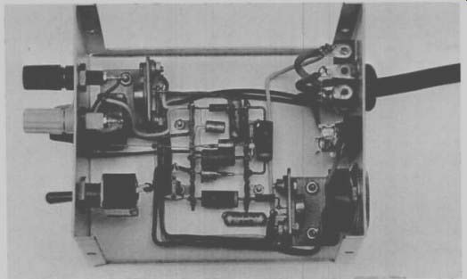
Fig. 35 - A professionally wired low frequency circuit.
For good heat conduction between the soldering iron and the mechanical joint, a small amount of solder should be applied to the tinned portion of the soldering-iron tip, and this surface should be applied to the joint. The solder is then applied to the joint, but is not brought into contact with the iron; when the solder melts, the joint is properly soldered. This procedure avoids a cold solder joint that could cause trouble at some future time. It is a good idea for the inexperienced circuit builder to practice soldering with some pieces of scrap wire.
The stripped ends of heavy solid wire or flexible multistrand wire such as used in line cords should be tinned before the mechanical connection to the lug or terminal is made. This tinning procedure ensures a quick, clean, hot solder joint. Tinning of heavy terminals such as those used on toggle switches is also a good practice. Tinning of ordinary hook-up wire is not necessary.
When a knife is used to strip the insulation from the end of a wire, it should be a dull one so that it will not nick the wire. If diagonal cutters are used, they should be squeezed only tightly enough to cut and pull the insulation. Wire-strippers must be set properly so that the wire being stripped is not nicked. A nicked wire can break and result in an inoperative circuit.
Heat Sinking
The dc power input to a semiconductor device generates heat within the device and raises its temperature. The maximum allowable device temperature rise limits the amount of electrical power input. Because the temperature rise depends not only on how much heat is generated, but on how fast that heat is carried away and dissipated, the amount of input power allowed is closely related to the heat-dissipation methods.
Medium- and high-power transistors are usually so constructed that they can be attached tightly to a chassis or to a heat sink. To aid in carrying heat away from the transistor junction, the collector junction is internally connected to the transistor case in most power transistors. Therefore, when the transistor case is connected to the chassis, the collector is also connected to the chassis, and some provision must be made to prevent shorting out of the de and ac voltages on the collector. Although it is possible to rearrange the circuit to allow the collector to be at chassis potential, the most usual practice is to insulate the transistor case from the chassis. This insulation must isolate the transistor from the chassis electrically while providing the least possible interference to the flow of heat from the transistor mounting base to the chassis.
Very thin (on the order of a few thousandths of an inch) mica, plastic, or anodized aluminum washers are used for this purpose. When anodized aluminum washers are used, care must be taken to remove any burrs on the transistor or chassis that might cut through the anodizing and destroy its insulating properties. To ensure the best possible heat transfer, a silicone grease or oil can be applied to both surfaces of the washer. The oil or grease fills any voids between the washer and transistor mounting base and the washer and chassis.
In the absence of a suitable metal chassis or in cases in which the device itself cannot be attached to a metal chassis, a heat sink is used. Heat sinks are produced in various sizes, shapes, and materials; they can be flat or cylindrical and can have vertical or horizontal fins attached to them.
Heat sinks also take the form of aluminum angle brackets. The device is normally attached to the angle bracket which is, in turn, attached to but electrically insulated from the chassis by the methods described above.
Grounding
A ground is a common reference point in a circuit; ground potential means that there is no potential difference, no voltage, between the point at ground potential and the earth.
Ground points need not actually be connected to the earth, but if the connection were made, there would be no effect on the circuit. A chassis ground designates a common point in a circuit at which power supplies and metal chassis are electrically tied together.
Good grounds are sometimes very important to proper circuit operation.
In an amplifier, for example, the ground minimizes the possibility that changes in the output will be reflected in the input and prevents regeneration.
A good ground is one that evidences extremely low resistance and that displays essentially no difference in potential between connections to the same ground point.
Fig. 36 shows the symbols for earth and chassis grounds.
CHASSIS GROUND EARTH GROUND
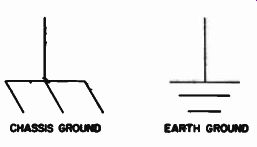
Fig. 36 - Symbols for chassis and earth ground.
SPECIAL HANDLING CONSIDERATIONS
Transistors
The collector, base, and emitter « terminals of transistors can be connected to associated circuit elements by means of sockets, clips, or solder connections to the leads or pins. If connections are soldered close to the lead or pin seals, care must be taken to conduct excessive heat away from the seals; otherwise the heat of the soldering operation may crack the glass seals and damage the transistor.
Under no circumstances should the mounting flange of a transistor be soldered to a heat sink because the heat of the soldering operation may permanently damage the transistor.
When the metal case of a transistor is connected internally to the collector, the case operates at the collector voltage. If the case is to operate at a voltage appreciably above or below ground potential, consideration must be given to the possibility of shock hazard and suitable precautionary measures taken.
Transistors should be handled care fully because the semiconductor material inside the case is brittle and can be damaged if the transistor is dropped. A drop of about 4-1/2 inches onto a hardwood surface can subject a transistor to a shock of about 500 times the force of gravity.
MOS Transistors
The performance of MOS transistors depends on the condition of a very thin insulating layer between the control electrode (gate) and the active channel. If this layer is punctured by accidental application of excess voltage to the external gate connection, irreversible damage can occur. If the damaged area is small enough, the additional leakage may not be noticed in most applications. However, greater damage may degrade the device to the point at which it becomes unusable. It is very important, therefore, that appropriate precautions be taken to ensure that the gate-voltage ratings of MOS transistors are not exceeded.
Static electricity represents the greatest threat to the gate insulation in MOS transistors. A large electrostatic charge can build up on the gate electrode if the transistor is allowed to slide around in plastic containers or if the leads are brushed against fabrics such as silk or nylon. This type of charge build-up can be avoided completely by wrapping the leads in conductive foils or fine wire, by use of conductive containers, or by otherwise electrically interconnecting the leads when the transistors are being transported.
A second cause of electrostatic charge damage to the gate insulation can be traced to the people who handle the transistors. At relative humidity levels of 35 percent, a person may accumulate an electrostatic potential that could range into the thousands of volts. If such a "charged" person grasps an MOS transistor by the case and plugs it into a piece of test equipment, or in any other way causes the gate lead to contact "ground" before the other leads, there is a good chance that the accumulated electrostatic charge may break down the gate insulation. To avoid this eventuality, those handling MOS transistors should make sure that they are grounded before touching the device.
In most applications, circuit impedances are low enough to prevent any accumulation of electrostatic charge.
Thus, although the gate insulation may be damaged by improper handling of MOS transistors before they are connected into actual circuits, thousands of hours of operation under practical circuit conditions have shown that the gate insulation is reliable under the stress of long-term operation within published ratings.
Integrated Circuits
The fabrication of any integrated circuit (IC) involves extreme care.
Special handling of the IC from the receipt of raw materials to the shipment of the finished product is the rule.
If the IC is to operate satisfactorily in its final application, this same special care must be followed in mounting and soldering. The best method of mounting transistor-can-type IC packages is to bend each lead out from the can slightly so that the lead ends describe a circle as close to the diameter of the mounting or socket holes as possible.
Care must be used in bending the leads to avoid breaking them off at the package base. After the leads have been bent, they can be inserted one by one into the socket or mounting holes.
The tab on the base of the IC designates the location of the highest-numbered lead. If the device is to be inserted into a socket, the tab should be matched with the tab or notch on the socket. If the IC is to be mounted on a printed-circuit board, for example, the leads should first be correctly positioned and inserted into the mounting holes. The top of the IC is then pushed down to move it closer to the board. All leads can then be soldered.
Serious damage to the IC can result from incorrect connection of leads.
When an IC lead is being soldered, a pair of long-nose pliers, an alligator clip, or other heat sink should be clamped to it between the soldering iron and the case. The soldering iron used should be small (45 watts); it should be very hot and in contact with a lead for the shortest possible period of time.
Correct polarity should be observed when a battery is installed in a circuit containing an IC; improper installation could seriously damage the IC
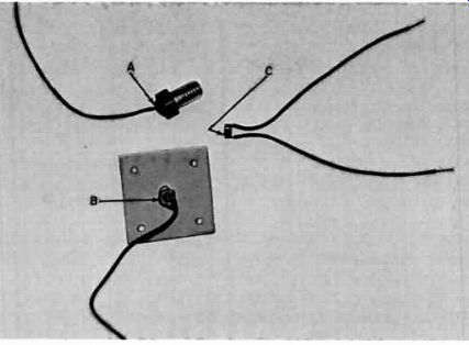
Fig. 37 - A few of the many possible thermistor mounting arrangements.
Thermistors
Thermistors are fragile devices that require special handling, particularly when they are being soldered to a mounting or when leads are being soldered to them. Only solder containing silver should be used; attempts to use common lead-tin solder will prove futile and will result in the removal or burning off of the silver coating on the thermistor. The solder recommended is a rosin-core type composed of 70 percent lead, 27 percent tin, and 3 percent silver.
Fig. 37 shows some of the many possible mounting arrangements for thermistors. In mounting A, the thermistor is soldered between a brass cap screw and a flexible lead. This type of mounting is useful at sub-freezing temperatures when one end of the thermistor is electrically connected to the frame or housing of the controlled device. In mounting B, the thermistor is mounted on a large heat sink so that short-duration, locally directed heat currents do not cause premature triggering of an alarm circuit. (For example, in a freezer, it is not desirable to trigger the alarm each time the door is opened for food removal.) The soldering technique used in attaching a thermistor to a cap screw is representative of that to be used in all thermistor mounting operations.
The technique is as follows:
1. Place the cap screw, head up, on an asbestos board or a sheet metal pedestal held in a vise.
2. Heat the cap screw by use of the small blue flame of a butane torch and apply enough silver solder to form approximately a 1/4-inch puddle on the top of the screw head; then remove the heat so that the puddle can solidify.
3. Reheat the cap-screw head until the solder melts. Then remove the heat and, by use of tweezers or long-nose pliers, carefully drop the thermistor on the melted solder and press it against the cap screw head until the solder re-solidifies. Then attach the flexible lead to the top surface of the thermistor by use of a small-tip soldering iron.
Wipe away any lead-tin solder from the tip of the iron with a piece of cloth before the following steps are taken.
4. Tin the soldering iron and the lead end with silver solder.
5. Place the tinned surface of the soldering-iron tip on the thermistor; apply a little solder to the thermistor to provide better heat conduction. Extra care is necessary at this point; too much heat will melt the solder between the thermistor and the cap screw and may appreciably alter the characteristics of the thermistor.
When a puddle of solder forms between the soldering iron and the thermistor, remove the iron and press the tinned end of the lead lightly into the solder; blow on the joint or fan it so that it cools quickly.
A similar procedure using a torch and a soldering iron should be used in preparing mounting B. A soldering iron is the only tool required to attach leads to a thermistor (mounting C). Thermistor characteristics can change as much as 20 percent as a result of the heat of a soldering iron.
The original characteristics are restored, however, after the thermistor has been in use for several hours.
Excessive heat can cause a wider change in characteristics and therefore requires a longer restoration period.
Photocells
A photocell can be conveniently connected to a circuit by use of a commercially available auto-radio antenna connector, with very little modification. The photocell and an exploded view of the disassembled antenna connector, H.H. Smith No. 1300, are shown in Fig. 38.
The only modification required in the connector is the drilling out of the brass insert in the black bushing nearest the photocell as shown in Fig. 38. In addition, the leads of the photocell should be covered with "spaghetti" type insulation to minimize the possibility of shorts.
Fig. 38 also shows the completely assembled device ready for use. The connector Pi is a standard Amphenol microphone connector and the lead is an insulated-shield microphone cable.
SAFETY PRECAUTIONS
Many of the circuits in this Manual are designed to operate from conventional 120-volt ac household power.
Much thought and care has been given to the design of these circuits to make them as safe as possible. However, certain precautions must be taken by the circuit builder to ensure maximum safety.
Three-wire input-power and output load connectors are recommended; where possible completely enclose all wiring and components. Ground a chassis containing a 120-volt circuit by connecting the pigtail lead on the input plug to the grounded housing of the 120-volt outlet. Always remove this plug from the outlet when the chassis is being serviced. Even if the fuse has blown, internal circuit components may still carry dangerous potentials. If voltage readings are desired during trouble-shooting, the circuit may be energized; however, it must be remembered that the case of some devices and other areas of the circuit carry dangerous voltages and should not be touched.
A good rule to follow during trouble-shooting of an energized circuit is to keep one hand away from the chassis, in a pocket if possible. It is also recommended that troubleshooting never be undertaken alone. Use safety glasses, especially during soldering; solder splashes are painful and can be dangerous. Also remove rings, brace lets, wristwatches, and the like during troubleshooting because they represent an electrical hazard.
----------
ANTENNA CONNECTOR MICROPHONE CONNECTOR SHIELDED MICROPHONE CABLE ASSEMBLED ANTENNA CONNECTOR AND PHOTOCELL
PHOTOCELL
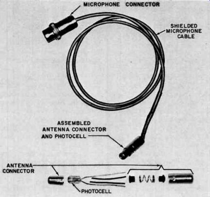
Fig. 38 - Method of mounting photocell for connection to 0 circuit.
++++++++++++