IN troubleshooting the circuits in this Manual is directly related to the circuit builder's familiarity with the instructions presented. The test instruments available and the way in which they are used are also very important factors.
Although waveshapes taken with an oscilloscope are not absolutely essential for troubleshooting, they can be valuable as an aid to understanding the operation of a circuit. Waveshapes taken when the circuits (especially the power-control type) are operating normally can be very useful for comparison purposes when trouble occurs.
Waveshapes shown in this book can be taken with an RCA WO-33A oscilloscope or its equivalent; the WO-33A is described at the end of this section.
Voltage and current readings can also be very helpful in troubleshooting. The RCA WV-38A Volt-Ohm-Milliammeter (VOM) and the RCA WV-77E VoltOhmyst are good instruments for such readings. Both of these instruments are also described at the end of this section.
The following checkout procedure is recommended when a circuit is first turned on or when troubleshooting is attempted:
*Trademark Reg. U.S. Pat. Off.
1. Before power is applied to the circuit for the first time, check the wiring for agreement with the schematic and check the load to ensure that it is within the circuit capabilities and is of the proper type.
2. If the circuit fails to operate, visually check the load for any signs of energization, such as the flash of a lamp or the start of a motor.
3. If trouble is evident remove the power-input cord from the power receptacle and check the fuse.
4. If the fuse has blown, recheck the wiring for short circuits; give special attention to the polarity of the electrolytic capacitors and silicon rectifiers.
5. If the fuse has not blown and the load shows no evidence of being energized, recheck the wiring; an open circuit caused by faulty wiring is the most probable cause of the trouble.
6. Voltage and resistance checks by VOM are the next step in isolating the trouble area. If one of the active components (transistors, diodes, or thyristors) is suspected, test it for "go/no-go" operation with one of the temporary circuits described and illustrated later in this section. (The tests that can be performed with the temporary circuits will only indicate whether the component under test is internally open-or short-circuited; they will not indicate how well or with what gain the component operates in the circuit.) More complete testing of transistor circuits can be accomplished through the use of a transistor tester such as the RCA WT-501A described at the end of this section. If all active components are found to be in working order, check the passive components, resistors and capacitors: capacitors for shorts and leakage, wire-wound resistors and potentiometers for discontinuities. These components, especially new ones that display no visible irregularities, are usually trouble-free and there fore are least likely to be the cause of circuit failure.
7. If the circuit is operating but the performance is not as expected, the trouble might be caused by the fact that the actual value of each component is a little higher or lower than its stated value. If all or substantially all of the components are off in the same direction (either higher or lower,) the sum of the small differences in individual resistance and capacitance might be enough to affect circuit performance. If this problem is suspected, a change to the next higher or lower resistance or capacitance value or the substitution of another component of the same value may produce a significant change in circuit operation. As mentioned previously, success in this type of troubleshooting depends to a large extent on the experimenter's familiarity with and under standing of the circuits involved.
TEST CIRCUITS FOR CIRCUIT COMPONENTS
The simple, temporary circuits shown in this section are designed to give the typical home circuit builder, who does not have professional-type testing equipment at his disposal, a means of testing circuit components.
Fig. 39 shows a simple "go/no-go" test circuit for silicon rectifier diodes operating at 120 volts. With the connection shown, the lamp operates at half-power. When the switch is closed, the lamp should brighten if the...
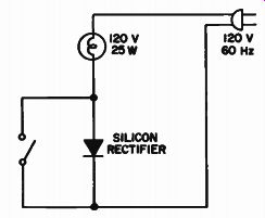
Fig. 39 - "Go/no-go" test circuit for high-voltage silicon rectifiers.
...diode under test is good. If there is no change in brightness when the switch is closed, the lamp was burning at full power with the switch open; in this case, the diode is shorted. If the lamp is out with the switch open but lights when the switch is closed, the diode is open.
Fig. 40 shows a "go/no-go" tester for all silicon rectifier diodes in this Manual that operate at low voltages except the 1N34A and 1N270. The test circuit for these two types is shown in Fig. 41.
With a diode connected as shown in Fig. 40 and with the polarity of the battery as shown, the lamp should light; when the polarity of the battery is reversed, the lamp should not light.
If the lamp lights regardless of the polarity of the battery, the diode is shorted; if the lamp does not light with either polarity, the diode is open.
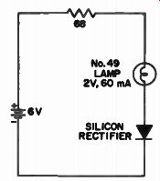
Fig. 40 - "Go/no-go" test circuit for low voltage silicon rectifiers
excluding types 1N34A and 1N270. When the anode of a 1N34A or 1N270 diode
is connected to terminal No. 1 in Fig. 41, the lamp should light if the diode
is good; when the anode is connected to terminal No. 3 the light should go
off. If the light remains lit regardless of the connection, the diode is shorted;
if the light is off regardless of the connection, the diode is open.
The test circuit shown in Fig. 41 can also be used to test MOS transistors.
The base and source should be connected to terminal No. 1, the gate to terminal No. 2, and the drain to terminal No. 3. If the MOS transistor is of the dual-gate type the gates are tested separately. If the lamp lights with the switch open, the transistor is good; if the lamp lights with the switch in either position, the transistor is shorted. If the lamp remains off with the switch closed, the transistor is good; if the light remains off with the switch in either position, the transistor is open.
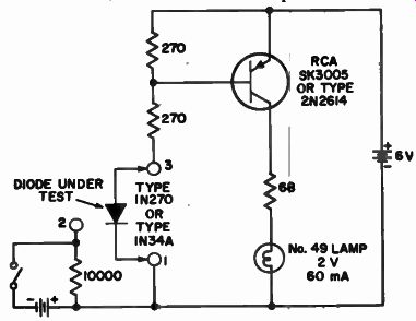
Fig. 41 - "Go/no-go" test circuit for silicon rectifier types 1N34A
and 1 N270 and MOS transistors.
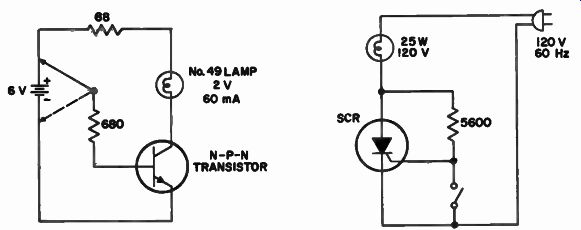
Fig. 42 shows a "go/no-go" tester for bipolar transistors. The connections
shown are for an n-p-n transistor.
When the base resistor is connected to the plus side of the battery, the No. 49 lamp should light if the transistor is operative. When the base resistor is connected to the minus side of the battery, the lamp should go out. For p n-p transistors, the same results should be obtained with the battery polarities reversed.
A quick check can be made of transistors prior to their installation in a circuit by resistance measurements with an electronic voltmeter such as the RCA VoltOhmyst* described at the end of this section. Resistance between any two electrodes should be very high (more than 10,000 ohms) in one direction and considerably lower in the other direction (100 ohms or less between emitter and base or collector and base; about 1,000 ohms between emitter and collector). It is very important to limit the voltage used in such tests (particularly between emitter and base) so that the breakdown voltages of the transistor will not be exceeded; otherwise the transistor may be dam aged by excessive currents.
Fig. 42 - "Go/no-go" test circuit for bipolar transistors.
Fig. 43 - Simple test circuit for SCR's.
SCR's can be tested by means of the circuit shown in Fig. 43. When the switch is closed, a current of approximately 20 milliamperes flows through the 25-watt lamp, the 5600-ohm resistor, and the switch; this amount of current is not enough to light the lamp.
When the switch is opened, the lamp should brighten to approximately half maximum brightness. Under these conditions, the SCR should be triggered into operation (shunting the 5600-ohm resistor) on each positive half-cycle of input by the 20-milliampere current flowing in the gate-cathode circuit. If the lamp lights to full ...
*Trademark Reg. U.S. Pat, Off.
... brightness, the SCR is shorted. If the lamp does not brighten regardless of the position of the switch, the SCR is open.
The test circuit shown in Fig. 44 can be used to check a two-transistor re generative switch. When the 1000-ohm resistor is inserted in the circuit, the No. 49 lamp lights. If the transistor switch is operating properly, the lamp should remain lighted when the 1000 ohm resistor is removed.
--------------- Table HI. Resistor/Capacitor Color Codes I. Does not apply to resistors or ceramic capacitors.
2. The first column through tolerance 9 applies to non-ceramic capacitors only: the remainder of the column applies to non ceramic capacitors and resistors. The second column applies to ceramic capacitors valued at more than 10 picofarads.
The third column applies to ceramic capacitors valued at less than 10 picofarads.
----------------
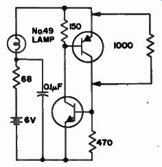
Fig. 44 - Simple test circuit for the two transistor regenerative switch.
RESISTOR AND CAPACITOR COLOR CODES
Standard color codes indicate the values of resistors and capacitors. Fig. 45 shows common composition resistors and the location of identifying marks; Table III explains the significance of the markings. A resistor with four stripes; yellow, black, green, and silver, respectively, from left to right, is 1 2 3 4 ...
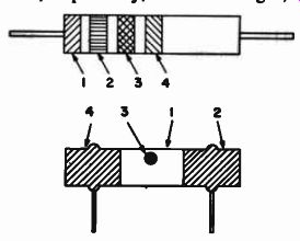
Fig. 45 - Location of identifying marks on common composition resistors:
... ( 1 ) first significant figure of resistance in ohms, (2) second significant figure, (3) decimal multi plier, (4) resistance to tolerance in percent (no color is ± 20%). a 4-megohm resistor with a ± 10-percent tolerance. A resistor with green, blue, and red stripes is a 5600-ohm resistor with a ± 20-percent tolerance.
Fig. 46 shows common types of capacitors and the location of their identifying markings; Table III explains the color-coded markings found on the capacitors. A flat or "postage-stamp" capacitor with 3 dots, left to right, of red, black, and red, has a capacitance of 2000 picofarads or 0.002 microfarad. A capacitor with 6 dots-top row, left to right, of brown, black, black, and bottom row, right to left, of black, gold, green-has a capacitance of 100 picofarads, a tolerance of ±5 percent, and a 500-volt rating.
Ceramic capacitors are valued in pico farads. They look much like resistors and are marked with bands (sometimes dots) to denote their characteristics. A capacitor with a broad violet band and successive narrow bands or dots of green, brown, black, and red has a capacitance of 51 picofarads and a capacitance tolerance of ±2 percent.
Transistor Tester
Convenience and efficiency in the testing and troubleshooting of transistor circuits is possible through the use of the RCA WT-50I A, a battery-operated completely portable transistor tester that can measure "beta" at the current level appropriate to a particular transistor. Beta is the common emitter forward current transfer ratio.
In the common-emitter circuit shown in Fig. 7 the base is the input electrode and the collector is the output electrode. The dc beta, therefore, is the ratio of the dc collector current Ic to the dc base current I B.
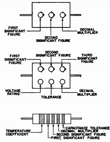
Fig. 46 - Location of identifying marks on common types of capacitors.
The WT-501A tests transistors out of circuit for dc beta from 1 to 1000, collector-to-base leakage (Iceo) as low as 1.0 microampere, and collector-to emitter leakage (Icco) from 20 microamperes to 1 ampere. Reliable in-circuit testing of transistor-current gain is made possible by special low resistance circuits. The collector current I_c is continuously adjustable from 10 microamperes to 1 ampere so that both low-power and high-power transistors can be tested.
Two sockets are provided on the panel, one socket for n-p-n transistors and the other for p-n-p transistors.
Three color-coded test leads are provided for in-circuit testing, or for use with transistors that do not fit the panel socket.
Additional features include a color coded panel for simplified operation and a mirror-scale meter to eliminate inaccurate readings due to parallax.
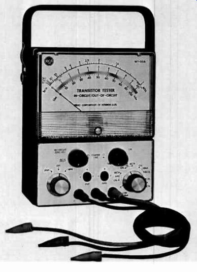
Fig. 47 is a photograph of the RCA WT-501A Transistor Tester.
Volt-Ohm-Milliammeter
The RCA WV-38A Volt-Ohm Milliammeter is a completely portable, all-purpose measuring instrument. It will measure ac sine-wave voltages from 0.1 volt to 5000 volts, dc voltages from 0.005 volt to 5000 volts, direct currents from 1 microampere to 10 amperes, resistances from 0.2 ohm to 20 megohms, and af output from -20 dB to +50 dB. Features of this versatile test instrument include a large, easy-to-read meter and a specially designed panel with two-color markings for simplified operation.
A convenient function switch is provided with ac, +dc, and -dc positions. The +dc and -dc positions of this switch reverse the polarity of the test leads. Fig. 48 is a photograph of the RCA WV-38A Volt-Ohm-Milliammeter.
Fig. 47 - The RCA WT-50I A Transistor Tester.
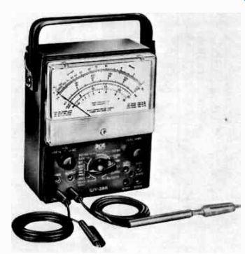
Fig. 48 - The RCA WV-38A Volt-Ohm-Milliammeter.
Volt Ohmyst*
The VoltOhmyst WV-77E is designed to measure dc voltages from 0.02 volt to 1500 volts, ac sine-wave voltages from 0.1 volt to 1500 volts, peak-to-peak voltages from 0.2 volt to 4000 volts, and resistance values from 0.2 ohm to 1000 megohms.
Additional features of the WV-77E include separate scales for low ac-voltage measurements to assure accurate readings, a circuit design which allows measurement of ac in the presence of dc and vice versa, and electronic protection against meter burnout. In addition, the resistors in the resistance divider network are protected by a separate fuse.
Fig. 49 is a photograph of the RCA WV-77E VoltOhmyst.
*Trademark Reg. U.S. Pat. Off.
Oscilloscope
The size and weight of the RCA WO-33A 3-inch oscilloscope make it an easily portable instrument, useful in troubleshooting, general waveform analysis, and square-wave and general testing of electronic equipment. The WO-33A is a versatile and reliable instrument, well suited to applications which require a dependable oscilloscope. A scaled graph screen and calibrated voltage source permit direct reading of peak-to-peak voltages.
The sweep-frequency control is continuously adjustable from 15 Hz to 75 kHz. The over-all frequency range of the oscillator is divided into four basic ranges; a vernier adjustment, which overlaps the basic sweep ranges, provides exact adjustment of the sweep frequency.

Fig. 50 is a photograph of the RCA WO-33A Oscilloscope.
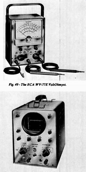
Fig. 49 - The RCA WV-77E VoltOhmyst. Fig. 50 - The RCA WO-33A Oscilloscope.
++++++++++++