4-1. Types of Sweep Generators
Sweep signal generators are those which provide frequency modulation of the r-f carrier signal, so that they may be used for sweep analysis of a response curve of a radio or tv receiver or other device. The methods by which such sweep analysis is accomplished are explained in Section 8.
In this section we are primarily concerned with the basic types of sweep generators and their principles of operation.
Sweep signal generators can be roughly divided into three classes: (1) those with a rather limited sweep range (up to about 1 mhz) designed primarily for f-m receiver alignment, (2) those designed for tv receiver alignment (sweep up to 15 mhz or so), and (3) special laboratory devices with greater sweep ranges.
Although some sweep generators of type (1) have been available, they are now in the minority in practical use. This is because those of type (2) nearly always have sweep-width controls which will allow adjustment of the sweep width to a low enough value to provide for f-m receiver alignment, as well as provide for the greater sweep width necessary for tv alignment. Type (3) generators are special laboratory equipment and not of as great an interest in the field as those of type (2). Accordingly, it is type (2) which we will be concerned with mainly.
4-2. Use of Reactance Tube for Frequency Sweep
The reactance tube is one of the main methods used for providing frequency modulation in sweep generators. Let us review briefly how a reactance tube works. The reactance tube produces artificially, by electronic means, the effect of capacitance or inductance. More important, it provides the means of varying the value of that capacitance or inductance by variation of a d-c control voltage applied. If the effective capacitance or inductance produced by the reactance tube is made to form an appreciable part of the capacitance or inductance of the tuned circuit of an oscillator, the frequency of that oscillator's signal can be made to vary by the variation of a d-c control voltage applied to the reactance tube.
If the d-c control voltage is made to alternate (that is, become low-frequency alternating current) the oscillator frequency also alternates and thus becomes a "sweep" frequency. This is the method used in some sweep generators to provide the desired frequency sweep.
A typical reactance tube circuit is shown in Fig. 4-1. The operation is as follows:
1. R-f is coupled to the plate and cathode of the reactance tube from the oscillator tank through C2 and C3.
2. This causes the reactance tube plate-cathode circuit to act as a load across the oscillator tank. The current drawn through this load depends upon the value of the grid bias, which in this case is the control voltage across R1.
3. Also across the oscillator tank circuit is the series combination C1-R1. This series circuit is designed so that the reactance of C1 is much greater than the resistance of R1. The current through this circuit is therefore leading the oscillator voltage applied by nearly 90 degrees. This current through R1 produces a voltage drop which is also nearly 90 degrees ahead of the oscillator voltage. This R1 voltage is applied to the grid of the tube and there acts to control the current in the plate circuit.
The plate current variations are in phase with the grid voltage variations. Since the latter are almost 90 degrees leading with respect to the r-f voltage applied from the oscillator, the plate current is also almost 90 degrees leading with respect to the oscillator r-f voltage.
The result of all this is that, looking from the oscillator toward the reactance tube, the oscillator sees a load which draws current that leads the applied voltage by nearly 90 degrees. Since this is exactly what would happen if a capacitor were connected in place of the reactance tube, the oscillator does not distinguish it from a capacitor, and its frequency is controlled accordingly.
The larger the capacitance, the greater r-f current it will draw from the oscillator; in the same way, the more positive (or less negative) is the control voltage on the reactance tube, the more current the tube draws. Thus the more positive the control voltage, the larger will be the capacitance exhibited by the reactance tube; the more negative the control voltage, the less the capacitance.
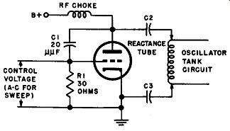
Fig. 4-1. Reactance-tube circuit, such as is used to frequency modulate the
r-1 oscillator in a sweep generator.
Now if the control voltage is made to vary rapidly back and forth, we produce the same effect as though we were rapidly rotating a variable capacitor across the oscillator tank circuit. This effect causes the oscillator to change frequency rapidly in accordance with the control voltage changes. In other words, the oscillator frequency "sweeps" back and forth.
In sweep generators of the reactance-tube type, a small voltage derived from the power line is applied as control voltage. This voltage is ordinarily a 60 hz a-c sine wave, and thus causes the oscillator frequency to vary sinusoidally.
In sweep generators, the sweep width is controlled by variation of the a-c control voltage applied to the reactance tube. The oscillator whose frequency is being swept is usually operated at a rather high frequency (the values in Fig. 4-1 are for an oscillator at 40 mhz) so that a given percentage of frequency deviation can produce as high as possible a sweep in megacycles. For constant sweep width with varying output center frequency, and for reasons of stability, the oscillator which is thus frequency modulated is usually kept at a fixed center frequency, while variable output center frequencies are obtained by heterodyning with another, unmodulated, variable frequency oscillator. This is explained more fully later in this section.
4-3. Use of Vibrating Capacitor for Frequency Sweep
The second method for obtaining frequency sweep is a mechanical method, usually employing a vibrating capacitor. This is a development from an older method, in which the shaft of a variable capacitor was made to rotate rapidly, causing the capacitance to change rapidly from minimum to maximum and back again in a regular periodic manner.
This capacitor, connected in an oscillator tank circuit, caused the frequency of the oscillator to sweep back and forth in the desired manner.
The more modern method frequently utilizes a capacitor whose plates can move closer or further apart. The spacing between them is varied by means of an electromagnet connected to an a-c power-line voltage.
The idea is shown in Fig. 4-2. In most cases the capacitor plates are cylindrical, as shown, with one moving inside the other. One plate is fixed in position, while the other is kept in motion by a coil-and-magnet arrangement (similar to the voice coil and magnet assembly of a loud speaker), actuated from an a-c voltage source. A springy suspension of some kind keeps the armature in its static position. As the moveable plate moves out of the stator, the capacitance becomes less; as it moves into it, the capacitance becomes greater. Since the voltage applied to the moving coil is alternating rapidly, the capacitor rotor plate is moved rapidly back and forth, thus rapidly varying the capacitance. As shown, the capacitor plates are connected across the oscillator tank coil. The rapid variations in capacitance cause rapid variations in oscillator frequency, and the desired sweeping action is accomplished. Frequently the stator is made in two sections so that a split-stator capacitor is formed.
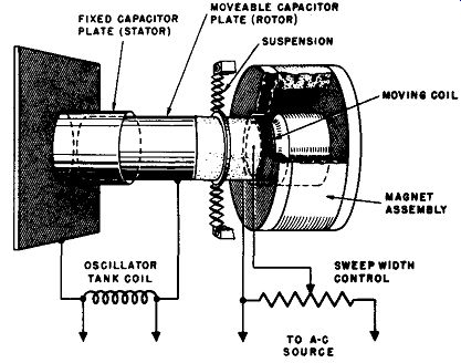
Fig. 4-2. Diagram showing the operation of a vibrating capacitor for sweeping
the r-f oscillator in a sweep generator.
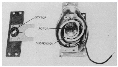
Fig. 4-3. Typical vibrating capacitor. Courtesy, RCA.
The distance the moving assembly travels back and forth depends upon how much voltage is applied to the moving coil. The amount of capacitance variation, and thus the sweep width, depends upon the distance through which the assembly moves. Consequently, the sweep width depends upon the voltage applied to the moving coil. This is the principle used in controlling sweep width in generators using modulation of this type. As shown in the figure, the sweep-width control is one which varies the voltage applied to the actuating coil.
A typical vibrating capacitor is illustrated in Fig. 4-3. Note that, to increase the capacitance and its variation, several coaxial plates are used in the capacitor. In this case, the rotor plates are grounded through the centering spider, and the split stator plates are insulated above ground by the insulating material at the top.
(Note: The type of electromechanical driving mechanism described above is also sometimes used to move a copper or aluminum disc toward and away from a coil which forms the inductance of the swept oscillator. As the disc is moved closer to the coil, the inductance is reduced and the oscillator frequency is raised. As the disc is moved away from the coil. the inductance is increased and the oscillator frequency is lowered. When a.c. is applied to the coil in the driving mechanism, the disc moves alternately back and forth and thereby causes the oscillator frequency to vary in step.)
4-4. Use of Controllable Inductors for Frequency Sweep
Still another method of producing frequency sweep is by the use of a controllable inductor such as the Increductor. [1] This is a special type of saturable inductor which operates at radio frequencies. In a saturable inductor, the effective inductance of a winding on an iron core is caused to decrease if the core is partially saturated with flux produced by current flowing in another winding.
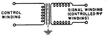
Fig. 4-4. Schematic diagram of o controllable inductor.
SIGNAL WINDING (CONTROLLED R-F WINDING)
1 . Trademark of C.G.S. Laboratories Inc.
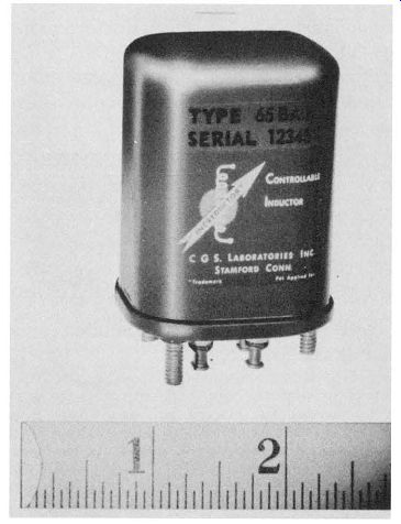
Fig. 4-5. A photograph ol a typical controllable inductor. Courtesy, C.G.S.
laboratories.
The schematic diagram of a controllable inductor is shown in Fig. 4-4. Note the use of the two windings: the control winding, to which the changing current is applied which produces the flu~ that partially saturates the core, and the signal winding, whose inductance is caused to change because of the changing flux in the core. This flux, as it approaches core saturation, reduces the permeability of the core and thus results in a reduction of effective inductance. The two windings are separated by an electrostatic shield, and are so arranged that practically no electromagnetic coupling exists between them. The entire unit is usually supplied in a hermetically sealed can, which may be mounted in any position. The appearance of one such typical unit is shown in Fig. 4-5.
In normal operation in a sweep generator, an alternating current at the line frequency is applied to the control winding. This causes the inductance of the signal winding to vary over a considerable range.
By using the signal winding as all or part of the inductance of an L-C tuned circuit of an oscillator, the oscillator frequency is made to vary back and forth at the line-frequency rate about a center r-f frequency.
In this manner, a frequency sweep is produced.
4-5. Phasing
When a sweep generator is being used to produce a response curve on an oscilloscope screen, the sweeping action of the generator frequency and the horizontal sweeping action of the oscilloscope beam should be synchronized not only in frequency but also in phase. If the phase relation is not properly adjusted, then one end of the oscilloscope horizontal trace does not correspond to the lowest frequency swept through by the generator, and the other end does not correspond to the highest frequency, as should be the case. This is illustrated in Fig. 4-6. In this figure, it is assumed that a sweep generator is sweeping between 20 and 30 mhz, and that it is being used to depict a response curve on an oscilloscope screen. To make the explanation clearer, the forward and return traces are shown separately (return trace below the forward trace) although in practice they usually coincide.
At (A) the phasing is properly adjusted, so the response curves swept during the forward and return traces coincide. The forward trace sweeps through the frequency, range from 20 to 30 mhz, while the return trace sweeps in reverse order, from 30 to 20 mhz. Thus, when phasing is proper, each point along the horizontal axis represents the same frequency for both the forward and return traces.
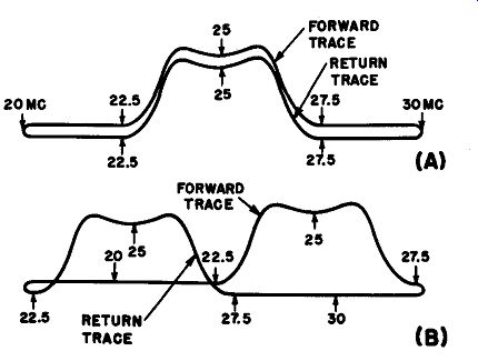
Fig. 4-6. The effect of (A) proper phase adjustment and (B) improper phase
adjustment in sweep-response analysis. The forward and return base-line traces
are shown separated for clarity, but in practice these would coincide.
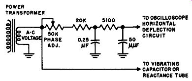
Fig. 4-7. A typical phase-adjusting circuit used in a sweep generator.
At (B) is shown what happens if the phasing is not correct. The sweep generator is starting from its low-frequency extreme (20 mhz) after the oscilloscope beam has started its forward sweep; by the time the sweep generator reaches 30 mhz, the oscilloscope beam has completed its forward sweep and started its return sweep. The result is that the for ward and return response curves do not occur at the same point along the horizontal axis and are staggered as shown at (B). The phase relation between the sweep-generator signal and the oscilloscope sweep is adjusted by a circuit between the generator and the oscilloscope deflection plates. This phase-adjusting circuit may be in the generator or in the oscilloscope, or sometimes there is one in each unit. A common method of obtaining sweep voltage for the oscilloscope and adjusting its phase in the sweep generator is shown in Fig. 4-7.
The a-c voltage for both the vibrating capacitor in the sweep generator and the deflection circuit of the oscilloscope are obtained from a low- voltage secondary winding of the power transformer in the sweep generator. The voltage is applied directly to the vibrating capacitor, but through the network shown to the oscilloscope horizontal input circuit.
The relative phase between the two outputs depends upon the adjustment of the 50k-ohm phase adjuster, which varies the amount of resistance in the circuit with the .25-uf capacitor.
4-6. Blanking
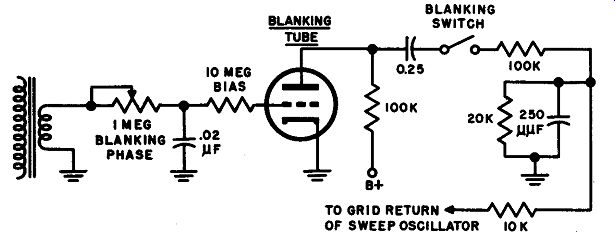
Fig. 4-8. A typical blanking circuit used in a sweep generator.
As shown in Fig, 4-6, there are actually two traces visible in ordinary sweep alignment or response-curve observation. One is the forward trace, as the oscilloscope beam sweeps from left to right, and the other is the return trace, when the beam returns from the right to the left. If the phasing is properly adjusted, as shown at (A) of Fig. 4-6, the response curve traces coincide (the traces are shown separately vertically in the figure for clarity, but coincide in practice) and the region under the traces is blank. Sometimes it is desirable to remove the return trace of the response curve by eliminating the generator r-f signal during the return-trace period. The oscilloscope beam then returns without vertical deflection, and forms a base line for the response curve in the forward direction. This process is known as blanking and a circuit to effect this is provided on many sweep generators.
A typical blanking circuit is shown in Fig. 4-8. Here the blanking tube is normally held cut-off by the bias developed across the large (10 meg) bias resistor. Under these conditions the sweep oscillator operates normally. During the positive alternations of the input a.c., the blanking tube conducts. It therefore operates to place a high negative bias voltage on the oscillator tube so the oscillator stops oscillating and the sweep-generator signal is absent. The blanking-phase control forms a phasing circuit with the 0.02-µ.f capacitor so that the phase of the blanking voltage may be adjusted to stop the operation of the sweep oscillator during exactly the proper time (while the sweep generator produces the reverse sweep and the scope retrace occurs). Examples of response curves with base lines produced by the blanking facility of the sweep generator have already been shown in Fig. 3-1.
4-7. Sweep-generator Combinations
Sweep generators are manufactured in a number of combinations with other auxiliary features. Many of them contain marker oscillators independent of the main sweep oscillator. Sometimes there are also calibrator arrangements for frequency checking of the markers.
Several combinations are available for providing practically all the units necessary for sweep-response analysis in one unit. For example, the Philco Visual Alignment Generator, Model 7008, and the Simpson Genescope, include sweep generator, marker generator, and oscilloscope all in one interconnected unit, controlled by switches from the front panel. In these units, the individual parts operate on the same principle and generally contain the same features as these units do when employed separately.
4-8. The Heterodyne Principle Employed in Sweep Generators
The methods used to sweep the frequency of the r-f oscillator, explained earlier in this section, are limited in the practical percentage of frequency change they can produce and still maintain symmetry, linearity, and stability. For this reason it is usually more feasible to modulate the frequency of an oscillator at a high, or moderately high frequency; then, with the same percentage of frequency variation, a wide sweep width can be obtained.
Accordingly, a large number of sweep generators employ the hetero-dyne system of adjusting center frequency while keeping the sweep at a constant width. Different manufacturers use different combinations of frequencies, but the block diagram of Fig. 4-9 will illustrate the idea.
The frequencies are not those of any particular model but are chosen to demonstrate how this system works. An oscillator is operated at a fixed center frequency of 100 mhz, and is connected to either a vibrating capacitor or a reactance tube, so its frequency is swept over the desired range.
A second oscillator is designed so that its frequency can be varied by adjustment of the main tuning knob, but its frequency is not modulated, or swept. This oscillator can be tuned either from l 00 to 200 mhz or from 200 to 300 mhz.
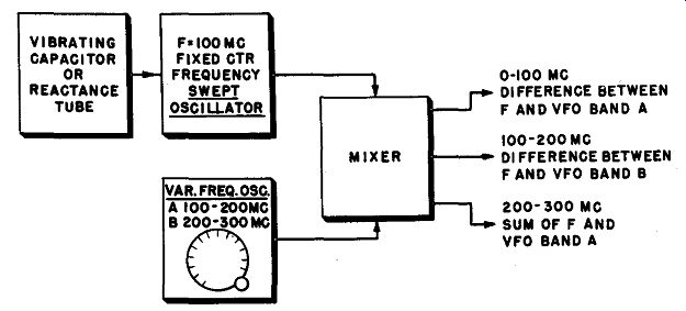
Fig. 4-9. How a variable-oscillator signal and a signal from a swept oscillator
with a fixed center frequency are combined to provide a wide range of output
frequencies with a constant sweep width.
The output signals from both these oscillators are fed to a mixer circuit where they heterodyne with each other to produce sum and difference frequency components. As shown in the figure, by proper use of the beat signals, a range from zero to 300 mhz is available. But the important factor in this case is not the range, which would be more easily available with a single oscillator. What is more important is that all the output beat signals have the frequency sweep of the same width as the swept oscillator. Since the output has either the sum or difference frequency, this output frequency must follow the frequency variations of the swept oscillator. Because no frequency multiplication has taken place, the width of the sweep is the same at all output frequencies. If harmonics of the swept oscillator were used, the sweep width, in mega cycles, would be multiplied by the same factor as the center frequency.
For example, in Fig. 4-9, if the second harmonic of the swept oscillator, instead of a heterodyne, were used for 200 mhz output, the sweep width at the harmonic frequency would be twice that obtained at the fundamental 100 mhz frequency.
In most generators to be used for sweep output only, the main dial is the frequency control for the variable oscillator. This dial is calibrated in terms of the heterodyne frequency which is actually to be used at the output, rather than in terms of the frequency of the variable frequency oscillator which it controls. The latter is of no particular importance to the user of the generator.
4-9. Generators in Which the Swept Oscillator Itself is Tunable
It is ordinarily not desirable to tune the center frequency of a swept oscillator through a range on continuously tuned sweep generators. This is because most tuning is accomplished by means of a variable capacitor.
If a vibrating capacitor is used for sweep, its varying capacitance is added in the circuit to that of the variable capacitor used for tuning. When the variable capacitor is adjusted for maximum capacitance, the vibrating capacitor is then only a relatively small part of the total circuit capacitance, and the sweep width is small. When the variable capacitor is adjusted for minimum capacitance, the vibrating capacitor is a large part of the circuit capacitance, and the sweep width is relatively large.
This would be highly inconvenient in the use of the generator, since each time the center frequency is changed the sweep width must be checked or adjusted.
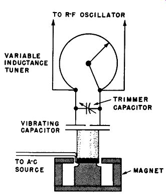
Fig. 4-10. Tuning and sweeping circuit of the Philco Model 7008 sweep generator,
in which the swept oscillator itself is also tunable through a range. The use
of inductance tuning allows tuning the center frequency through a range without
much change in sweep width.
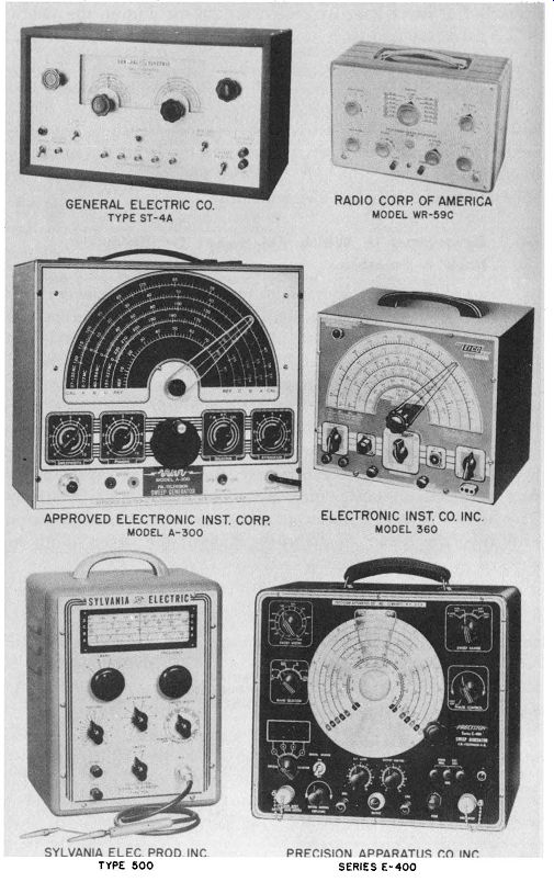
Fig. 4-11. Photographs of typical, modern sweep generators.
Note: The above photos are reproduced through the courtesy of the manufacturers indicated.
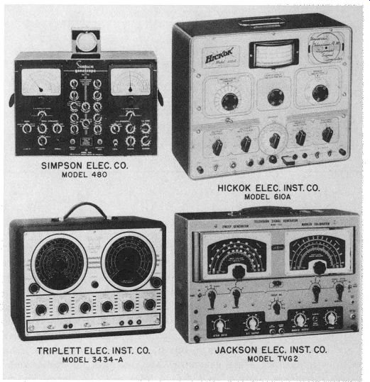
Fig. 4-12. Photographs of typical, modern combination sweep and marker generator
units.
Note. The above photos are reproduced through the courtesy of the manufacturers indicated.
However, when the oscillator is designed to be tuned by variation of inductance instead of capacitance, the swept oscillator can be tuned through a range of frequencies without too much variation of sweep width. This is because the variation of capacitance of the vibrating capacitor remains the same percentage of the total circuit capacitance as the frequency is changed by variation of the inductance. A typical oscillator circuit tuned by inductance and swept by a vibrating capacitor is shown in Fig. 4-10. The swept oscillator can thus be varied over its own center-frequency range, and this oscillator can be used directly for output over that range. For other ranges it is simply heterodyned with a fixed-frequency unmodulated oscillator to provide sum and difference frequency outputs.