Introduction
THE collector current of a junction transistor consists of two components, one controlled by the base current and the other independent of it. The first component is useful because the amplifying properties of the transistor depend on it: the second is useless and is usually known as the leakage current. The leakage current is caused by thermal dissociation of covalent bonds as described in Chapter 1 and is strongly dependent on temperature; at high temperatures it may become comparable with the useful current, causing severe limitations in the performance of the transistor. For example, if the leakage current is an appreciable fraction of the total collector current, it is impossible for the collector voltage to swing up to the collector supply voltage under the action of an applied signal: thus the undistorted output-voltage swing is reduced by the presence of the leakage current.
Leakage current can, under certain conditions, cause damage to or even destruction of a transistor. For such a current heats up the collector junction, causing further increase in collector current which accelerates the heating process. Unless precautions are taken to prevent the collector current rising, a regenerative process can occur, resulting in an abnormally large collector current which, if it exceeds the safe collector dissipation, can cause damage to the transistor.
Transistor circuits must be designed to prevent this thermal runaway by limiting the collector current to a safe value. Such protective circuits also tend to make the performance of the equipment less dependent on the parameters of the transistors, permitting the exchange of one transistor for another.
LEAKAGE CURRENT IN A COMMON-BASE AMPLIFIER
Consider a junction transistor used as a common-base amplifier such as that shown in Fig. 6.1. If the emitter battery circuit is broken, the collector current falls to a low value which is due to the reverse current of the diode formed by the collector-base junction. This current is the leakage current referred to above and is represented by lco. When the emitter circuit is restored, the collector current rises due to the addition of the useful current alpha_le from the emitter circuit. Thus the total collector current le is given by:
le= alpha_le + lco .... ( 1)
For a small junction transistor the leakage current is very small, a typical value being 5 /LA at a temperature of 25° C. It increases substantially exponentially with temperature and may reach 50 /LA at 55° C, but even so is still small compared with alpha_le which may be 1 mA. Thus it may be said that leakage current has a negligible effect on the performance of a common-base amplifier, and provided
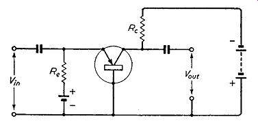
Fig. 6.1. Simple uncompensated common-base amplifier which has good thermal
stability
Re and Rc are chosen to keep the collector dissipation below the maximum safe value, the likelihood of thermal runaway docs not exist.
Protective circuits are thus unnecessary in a common-base amplifier. Such an amplifier is said to have good d.c. stability and, in fact, it is the aim in the design of common-emitter transistor amplifiers to achieve d.c. stability comparable with that of a common-base circuit.
LEAKAGE CURRENT IN A COMMON-EMITTER AMPLIFIER
For a number of reasons which were listed earlier, the common emitter amplifier is preferred in transistor circuitry to the common-base amplifier. The basic circuit for a common-emitter amplifier is given in Fig. 6.2.
If the base resistor circuit is broken in this amplifier, there is a residual current flowing between collector and emitter. How ever, this current arises from a process somewhat different from that producing the leakage current in a common-base amplifier.
The collector-base junction is reverse-biased as in a common-base amplifier and there is hence a collector-base leakage current of ...
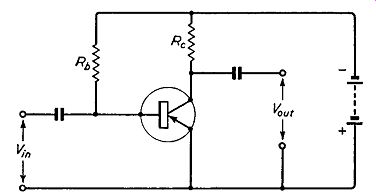
Fig. 6.2. Simple uncompensated common-emitter amplifier which has poor thermal
stability
... magnitude Ico as before. There is, however, no net external base current (because the circuit is disconnected) and it follows that there must be an emitter-base current, also equal to I_c0, but flowing in the opposite direction to the collector-leakage current.
This current behaves as an input current and is magnified by transistor action, appearing as a current of alpha I_c0 in the collector circuit where alpha ' = alpha / (1- alpha).
Thus the total leakage current in the collector circuit is:
This is usually represented by I_c0':
alpha ' is not so large as in signal calculations but lc0' can be consider ably greater than Ico. In fact at 25° C for a small junction transistor lc0' can be as much as 250 µ,A rising to 2.5 mA at 55° C; this is more than twice normal values of signal current and can cause great deterioration in circuit performance. It is essential, therefore, in common-emitter transistor amplifiers to include protective circuits to avoid undue rise in collector current.
On the other hand the very large leakage current of the common emitter amplifier is of great value in photo-transistors as explained in Chapter 13.


In general, for a common-emitter circuit
.... (2)
where alpha_' lb is the useful component of the collector current and lc0' is the leakage current.
STABILITY FACTOR
Suppose there is a change of leakage current 11lc0' due to a change of temperature in an un-stabilized circuit. If the useful current alpha_' I_b remains constant, this causes an equal change in the total collector current le, Now suppose that a stabilizing circuit is applied to the transistor amplifier. Over the same temperature range, this has the effect of reducing the change in collector current to a smaller value than that which occurred in the un-stabilized circuit. The ratio of the two changes is known as the stability factor K.
Hence: K = change in total collector current in stabilized circuit change in total collector current in un-stabilized circuit The change in collector current in the un-stabilized circuit is due entirely to a change in the leakage current, if, as assumed here, the useful component of collector current is constant. Thus K is given by
K = delta_Ic 11lc0'
For an un-stabilized circuit delta_Ic = 11lc0' and K = I.
For a stabilized circuit delta_Ic is smaller than 11lc0' and K is less than unity, the smallness of K being a measure of the success of the stabilizing circuit.
Values of K of 0.1 or less can quite easily be achieved by conventional circuits, and this shows that the variations in collector current caused by, say, a given temperature change, are less than 1/10th the change which would occur in an un-stabilized circuit.
PROTECTIVE CIRCUITS FOR COMMON-EMITTER AMPLIFIERS
Use of a Collector-base Resistor
A simple method which can be employed to increase the d.c. stability of a common-emitter amplifier is that illustrated in Fig. 6.3.
This is similar to the circuit of Fig. 6.2 but the difference is that the resistor Rb is returned to the collector instead of to the negative terminal of the supply.
The improvement can be explained qualitatively in the following way. Suppose the leakage current increases as a result of an increase in temperature. This causes an increase in the voltage across the collector load Re and the collector potential becomes more positive. The base input current is primarily determined

Fig. 6.3. A simple method of improving the thermal stability of a common-emitter
amplifier by the resistance Rb and the collector voltage, and this change
in collector voltage causes a reduction in base current and hence in the
useful component of collector current. This in turn causes a negative movement
of collector potential and a process of re adjustment occurs, ending with
a total collector current greater than the original value but not so great
as in an uncompensated circuit such as that shown in Fig. 6.2.
The precise improvement in d.c. stability afforded by this simple circuit can be calculated in the following way. From equation (2)
we have
.... (3)
The base-emitter voltage is usually small compared with the collector supply voltage V and thus we may say
From (3)
BIAS STABILIZATION
lbRb + (lb + le)Re = V
Substituting for lb in (4)
(le - :,eo')Rb + (le ~,1eo' + le)Re = V
Rearranging this we have le[Rb + (a' + l)Re] = le0'(Rb + Re) + a'V
Differentiating with respect to:
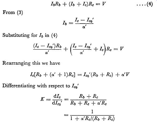
.... (4)
Re, Rb and o:' are all positive quantities and this expression shows that the stability factor K is less than unity. The aim, of course, is to get the best stability, i.e. the lowest possible value of K. This implies a high value of alpha ', a large value of Re or a small value of Rb.
There is not usually much choice of value of alpha ' and this is not likely to exceed 50. Re and Rb cannot be varied at will to secure good stability because their values have to satisfy other and more important considerations.
For example, Re is the collector load resistance and its value is determined by the collector supply voltage and the mean collector current of the transistor. Rb supplies base bias and its value, together with that of the collector supply voltage, determines the bias current. Thus the d.c. stability obtainable from this circuit is to a large extent determined automatically by other design requirements.
To indicate the value of stability likely to be obtained, we will consider a typical common-emitter amplifier and will calculate likely values for Re and Rb. If the collector supply is -6 volts and the mean collector current is l mA, a suitable value for Re is 3 k-ohm, for this gives a mean collector voltage of - 3 volts which permits upward and downward swings of collector voltage of approximately 3 volts peak value.
If the mean collector current is 1 mA and alpha_.' is 50, the mean value of the base current is approximately 1 /50 mA, i.e. 20 µA. The base-collector voltage is 3 approximately and to give the required value of base current, Rb must be 3/(20 X 10~) ohms, i.e. 150 k-ohm.
The stability factor is thus given by:
This is not a great improvement over the un-stabilized circuit.
A better performance is possible if the amplifier is not required to give a large signal output. For example, if the output voltage swings never exceed 1 volt it would be possible to operate with a mean collector voltage of -1 volt. For 1 mA mean collector current the collector load-resistance must now be 5 k-ohm, and for 20 µA mean base current Rb is given by
1 / (20 X 10^-6) = 50 k-ohm.
The d.c. stability is now given by:
The resistor Rb forms with the resistance of the signal source (not indicated in Figs. 6.2 and 6.3) a potential divider which returns a fraction of the output voltage of the amplifier to its input.
This causes a reduction in gain which, if not desirable, can be eliminated by constructing Rb of two resistors R1 and R2 in series,
the junction being connected to earth by a low-reactance capacitor as shown in Fig. 6.4.
If R1 is small, it shunts the collector load resistance of the amplifier, and if R2 is small, it shunts the input terminals and lowers the input resistance. Usually, therefore, R1 and R2 are made approximately equal and the capacitor is chosen to have a "'i'"

Fig. 6.4.
To avoid negative feedback due to Rb, decoupling may be introduced as shown here
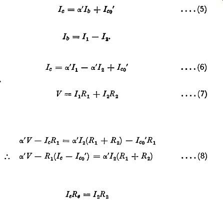
Fig. 6.5. Method of decoupling which can be used with transformer coupling
I
... reactance which is small compared with the resistance value at the lowest frequency it is required to amplify. For example, if Rb is 100 k-ohm, R1 and R2 can be 50 k-ohm and, for an a.f. amplifier,
C1 can be 2 µF which has a reactance of approximately
1.6 k-O at 50 hz.
If this simple method of stabilization is employed in a common emitter circuit which is coupled to the previous stage by a trans former, then the base end of the stabilizing resistor Rb can be decoupled to the emitter directly as shown in Fig. 6.5.
Use of a Potential Divider and Emitter Resistor
A better method of ensuring good d.c. stability in a common emitter transistor amplifier is illustrated in Fig. 6.6. It employs three resistors, two forming a fixed potential divider across the collector supply battery and a third included in the emitter circuit of the transistor. The emitter resistor gives negative feedback

Fig. 6.6. Potential divider method of stabilizing the d.c. conditions in
a common-emitter amplifier (a) in an RC-coupled amplifier and ( b) in a trans
former coupled amplifier. Arrows indicate electron flow and a consequent
reduction of gain: if this is undesirable, the emitter resistor can be decoupled
by a low-reactance capacitor, this constituting the fourth additional component
required in this method of stabilization.
Two basic versions of this circuit exist. In Fig. 6.6 (a) the circuit is arranged for RC coupling from the previous stage: a feature of this arrangement is that the resistance of R1 and R2 in parallel is effectively shunted across the input circuit of the transistor. This parallel resistance should not, therefore, be too small.
In Fig. 6.6 (b) the circuit is arranged for transformer coupling from the previous stage: the parallel resistance of R1 and R8 does not now enter into input-resistance considerations.
The improvement in stability due to this circuit can be explained in the following way. The base is connected to the junction point of the potential divider and, if we neglect any variations in base current, has a constant voltage. The transistor takes an emitter current such that the emitter voltage is practically equal to the base voltage. If now the leakage current increases, due to a rise in temperature, the emitter voltage tends to approach that of the base and the base-emitter voltage therefore tends towards zero; tends, that is, to reduce collector and emitter currents. This offsets the increase in leakage current, and in the resulting state of equilibrium the collector current is greater than it was initially but is less than in an un-stabilized circuit. In practice, variations in base current cause the base voltage to vary slightly and complete stabilization of the collector current cannot be achieved. Nevertheless, the circuit is capable of reducing variations in collector current to say 1/15th of their value in an un-stabilized circuit.
This is illustrated in the following analysis of the circuit.
From expression (2) we have But from Fig. 6.6 (a)
Substituting for h in (5)
Moreover

.... (5)
.... (6)
.... (7)
Eliminating / 1 between (6) and (7) by multiplying (6) by Ri, (7) by Ol.
1 and subtracting, we have
(8)
The voltage drop between base and emitter is very small. Thus giving:
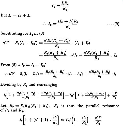
.... (9)
.... (10)
an expression similar to that for the previous circuit, with Re in place of Re. In both circuits Rb is the resistance in the external base circuit.
To obtain good stability K must be small and this requires a high value of alpha ', a high value of Re and a small value of Rb. In the circuit previously described the stability similarly depended on Rb and Re but the values which could be used were to a large extent dependent on other design considerations. In this circuit Rb and Re can be given any values necessary to achieve the desired stability within wide limits without significant effect on the performance of the circuit as an amplifier. Naturally there are some limitations on permissible values of Rb and Re in the potential divider circuit: for example, if Rb is made very small it makes the input resistance very small in an RC-coupled amplifier such as that illustrated in Fig. 6.6 (a). Moreover when Rb is small it is possible that the potential divider may take a very large current from the collector-supply voltage. This applies to the circuits of Figs. 6.6 (a) and 6.6 (b). As Rb is decreased towards zero, the circuit degenerates into a common-base type and, as shown in expression (10), K tends to 1/(1 + alpha '), which is its value for a common-base amplifier.
The stability factor also improves as Re is increased, but if this is made too large it will limit the collector current which can be achieved, unless a large value of collector supply voltage is used.
At the other extreme, when Re approaches zero and if Rb is high, the circuit becomes a simple common-emitter type with its particularly poor d.c. stability.
Design of a Potential Divider Circuit
Let us assume Re is to be 1 k-O: this is a convenient value because, for an emitter current of 1 mA, it loses only 1 volt of the collector supply voltage, leaving in a typical circuit with 6 volts supply, 5 volts for the transistor and its load resistor. If alpha ‘ = 50, the base current is 1/50 mA, i.e. 20 µA. This flows through R1 in addition to the bleed current which flows through R1 and R2 from the collector supply. For good d.c. stability the potential at the junction of R1 and R2 must be steady in spite of variations in base current and this is achieved by making the parallel resistance of R1 and R2 small: this implies that the bleed current must be large compared with the base current. The bleed current can therefore be 200 µA which is ten times the base current but is still only one-fifth of the collector current. Thus the total current in R1 is 220 µA. The voltage across R1 is 5 volts because the potential at the junction of R1 and R2 does not differ appreciably from the emitter potential. Hence R1 is given by:
Approximately
The voltage drop across R2 is 1 volt and the current in it is 200 µA, giving the value of R2 as 5 k-O.. C1 should have a reactance small enough to avoid negative feedback and consequent fall in gain even at the lowest operating frequency. To achieve this the reactance must be small compared with the internal emitter resistance of the transistor: a typical resistance value is 25 ohms.
In an a.f. amplifier C1 may be 500 µF which has a reactance of 6·5 ohms at 50 hz.
For this circuit Rb is given by:
The stability factor is thus given by:
a considerable improvement over the stability factor obtainable from the circuit described before. This value of stability factor is, in fact, only 4·5 times worse than that for the common-base amplifier (for which K is 1/(1 + alpha ') i.e. 1/51). In a common-emitter amplifier so stabilized when temperature increases the collector current increase is approximately 1/10th that which would occur if the amplifier were un-stabilized. To improve stability still further a means is required of making the potential at the junction of R1 and R2 slightly more positive as temperature rises. One method of achieving this is to connect in parallel with R2 a resistor with a value which decreases as temperature rises.
There are a number of different types of temperature-sensitive resistors having such a negative coefficient: one example is the thermistor. The coefficient required for good stabilization can be obtained by choosing the correct ratio of R2 to thermistor resistance.
Alternatively the stabilization can be improved by using for Re a resistor with a positive temperature coefficient: an example of such a circuit is given on p. 92.
Use of a Two-battery Supply
The potential-divider circuit reduces variations in collector current by stabilizing the base potential. However the base current flows through R1 and variations in base current must cause some variations in base potential and hence in collector current, although these can be made slight. Thus the circuit is not completely successful although, as we have shown, it can give a considerable improvement in d.c. stability.
Instead of using a potential divider to stabilize the base potential of a common-emitter amplifier, a battery may be used instead.
In pnp transistors the base must be biased negatively with respect to the emitter and it is thus unnecessary to use a separate battery for this purpose; the base can be returned to a tapping point on the collector supply battery as indicated in Fig. 6.7. This method of stabilization is shown applied to an RC-coupled common-emitter amplifier at (a) and to a transformer-coupled amplifier at (b). In an RC-coupled circuit it is not possible to connect the base directly to the tapping point without short-circuiting the amplifier input. A base resistor Rb must be included, and this necessarily degrades the d.c. stability by permitting variations in base potential.
Rb should therefore be given the lowest value consistent with reasonable gain from the previous stage. Better stability ( equal in fact to that of a common-base amplifier) is obtainable from the transformer-coupled circuit because no base resistor is necessary.
The only external resistance in the base circuit is that of the trans former secondary winding, and this can be very small, usually less than 100 ohms.
The two-battery circuit is very simple to design. If it is required to stabilize the collector current at, say, 0.5 mA, and if the tapping
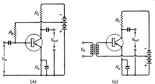
Fig. 6.7. Two-battery method of stabilizing the d.c. conditions in a common-emitter
amplifier (a) in an RC-coupled amplifier and ( b) in a transformer-coupled
amplifier point is chosen to give a base-emitter voltage of -1.5, the emitter
resistance Re is given by 1.5/(0.5 x 10^-3), i.e. 3 k-O. This circuit does,
however, require a slightly larger battery than other circuits.
The stabilizing voltage is, in effect, subtracted from the collector supply voltage, and a larger battery is needed to maintain adequate voltage across the transistor and its load resistance.
Use of a Temperature-dependent Emitter Resistor
The variations in collector current so far discussed are due to changes in leakage current: as explained these variations set an upper limit to the temperature at which a transistor can give a satisfactory performance. These variations occur even in the absence of the useful component alpha_le, i.e. even if the transistor is cut off.
The useful component alpha_le is also strongly dependent on tempera ture and, if temperature falls low enough, can become so small that the required collector current swing is impossible to achieve.
This variation thus sets a lower limit to the temperature at which satisfactory operation can be obtained. The variations in leakage current and useful component together define the temperature range within which satisfactory operation of the transistor is possible.
Both components of the collector current of a transistor thus vary with temperature but the total change in collector current can be reduced by using the methods of d.c. stabilization discussed above.
In a power transistor designed for collector dissipations of several watts, the collector current may be of the order of 0.5 ampere. This is large compared with the leakage current and variations in collector current are almost entirely due to changes in the useful component. The mean value of the useful component can be kept constant by adjustment of the base-emitter voltage and a change of approximately 2.5 mV per °C is required by silicon and germanium transistors. Thus the stabilizing circuits for power transistors should be designed to apply a correction of this value to the base-emitter voltage.
A simple method of effecting this compensation is to use an external emitter resistance of pure metal. Such resistors have a positive temperature coefficient and, if the base potential is constant, a rise in temperature causes the external emitter resistance to increase, thus increasing the voltage across this resistance. This in turn reduces the emitter-base voltage and thus tends to maintain the collector current constant.
The temperature coefficient of electrical resistance of copper is approximately 0.004 per °C: if the emitter current is assumed constant the voltage across a copper emitter resistance therefore increases by 0.004 of its initial value per °C. If the initial voltage is unity, the increase in emitter potential is 4 m V per °C. To offset a 2.5 mV change in emitter-base voltage, an initial emitter voltage of 2.5/4, i.e., approximately 0·6 volts, is needed. If the emitter current is 0.5 A (as is likely in a transistor of 5 W dissipation) the emitter resistance should be 0.6/0.5, i.e. 1.2 ohms, a convenient value to construct of copper wire. The fixed base potential is usually achieved by use of a resistive potential divider as discussed above.