4-1. Resistance Measurement; Voltmeter-Ammeter Method
One of the most direct approaches to resistance measurement, and perhaps the simplest in principle, is simultaneous measurement of both the voltage across and the current through a circuit or component. We know from Ohm's law that resistance equals voltage divided by current, and thus can calculate resistance from the voltage and current readings taken.
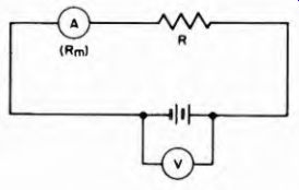
Fig. 4-1. Circuit for the voltmeter-ammeter method of measuring resistance.
The circuit for the voltmeter-ammeter resistance measurement method is illustrated in Fig. 4-1. It is seldom used except by students studying basic electronics, because the ohmmeter is abundantly available as a resistance measuring device.
For accurate results in measuring resistance by the voltmeter ammeter method, the relative resistances of the voltmeter and ammeter themselves must be kept in mind. For low values of R (comparable with the internal resistance of the ammeter A) the resistance Rm must be deducted from the value of the circuit resistance, determined by dividing the voltage F by the current indicated on A. For higher values of R, the circuit shown is satisfactory without worrying about Rm.
4-2. The Ohmmeter
The ohmmeter is an instrument that measures the d-c resistance of a circuit element or network, indicating the value of resistance on a meter scale calibrated in ohms. It is also used to locate open circuits and to check circuit continuity, and can be used to provide a rough check on capacitors. In application, the ohmmeter is one of the fundamental test instruments, along with the voltmeter and ammeter.
Basically, the ohmmeter consists of a sensitive current meter, a source of low d-c voltage, and some form of current-limiting resistor.
The meter itself is usually of the conventional moving-coil permanent magnet type, and a battery supplies the d-c voltage.
The values of d-c resistance encountered in electronic equipment vary from fractions of an ohm to many millions of ohms (megohms). Consequently, most ohmmeters are constructed to cover a number of ranges from very low to very high resistance. This is accomplished by connecting various values of current-limiting resistors into the ohm-meter circuit. The individual ranges can be selected as required by means of individual input terminals or a selector switch. Multi-range ohmmeters are discussed further in Section 8.
4-3. Series-Type Ohmmeter
Figure 4-2 illustrates the circuit of the basic series-type ohmmeter.
A 4.5-v battery and a variable resistor, RA, are connected in series with a milliammeter. The two leads labeled P1 and P2 represent test prods which are connected across the resistance to be measured, Rx The meter is 0-1 ma movement, requiring 1 ma of current for full-scale deflection.
The internal resistance of the meter, RM, is 50 ohms. The variable resistor RA adjusts the series resistance in the circuit so that 1 ma full-scale current flows when the test prods are shorted together. This occurs when the total series resistance is 4,500 ohms (4.5 v/4,500 ohms = 1 ma). In the circuit shown, the meter resistance (50 ohms) and RA (4,450 ohms) make up the required series resistance of 4,500 ohms.
When the test prods are shorted together, current flows through the circuit and the meter pointer is deflected across the scale, usually to the right. The resistor RA is then adjusted to provide full-scale deflection of the pointer. This position of the pointer corresponds to zero external resistance, since the two connected prods represent a short circuit across the ohmmeter terminals. In the series-type ohmmeter full-scale deflection of the meter pointer indicates the lowest resistance; the opposite end of the scale represents the highest resistance. A knob on the front of the ohmmeter marked zero-ohms-adjust controls RA.
In most cases RA consists of two resistors, one fixed and one variable, whose total value is equal to, or slightly more than, the value required for Rx. As the battery ages its terminal voltage decreases. Consequently, the variable zero-ohms resistor portion of RA compensates for this decrease. The current can be increased to the required value by an adjustment of this variable resistor which decreases the total series resistance. The zero-adjusting resistor RA can be connected either in series or shunt with the meter to provide the same function. When it is connected in shunt, a fixed resistor is connected in series with Ri ( and both resistors are connected across the meter. Another fixed resistor is then required in the series-ohmmeter circuit to limit the current to the approximate required value. The final current is adjusted by RA. For accuracy in meter readings, a zero-ohms adjustment must be made each time the ohmmeter is used.
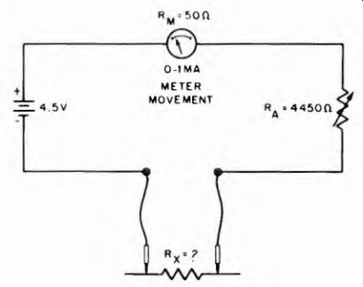
Fig. 4-2. Circuit of simple series type ohmmeter.
After the ohmmeter has been adjusted for full-scale deflection, the test prods are separated and the meter-pointer returns to the open-circuit position on the left of the scale. Placing the prods across the unknown resistor connects the latter in series with the ohmmeter circuit.
As a result the current is reduced proportionately, and the meter no longer deflects full-scale. If the value of RA is equal to the combined resistance of the current-limiting resistor RA and the internal resistance of the meter, or 4,500 ohms, the total circuit resistance then becomes 4,500+4,500, or 9,000 ohms. The current in the circuit now becomes I = E/R - 4.5/9,000 = 0.0005 amp, or 0.5 ma. Thus the pointer is now deflected only to the half-scale point, which for this ohmmeter is calibrated to indicate 4,500 ohms. If the value of another unknown resistor should be twice as great as the circuit resistance of the ohmmeter, then the total resistance is tripled and the current is reduced to one-third the full-scale deflection value. Accordingly, the meter pointer deflects to one-third full scale. This point represents a measured resistance of 9,000 ohms.
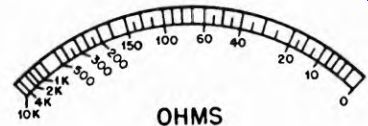
Fig. 4-3. Typical meter scale for series type of ohmmeter.
In this way the remainder of the meter scale is calibrated for ohmmeter use. A typical series-type ohmmeter scale is shown in Fig. 4-3. Notice how crowded the divisions become at the high-resistance (low current) end of the scale. For this reason, readings should always Be taken in the higher-current (lower resistance) three-quarters of the scale, and the scale (or range) used should be chosen to make this possible.
4-4. Shunt-Type Ohmmeter
For reading very low values of resistance, the shunt-type ohmmeter circuit is better than the series-type just described. The shunt-type ohmmeter circuit is shown in Fig. 4-4. The unknown resistance Rz is now shunted across the meter, instead of in series with it. With the unknown resistance connected in this manner, some of the current in the ohmmeter circuit takes the path through Rz. The current through the meter is reduced accordingly, and the amount of deflection drops proportionately. The current passing through the meter depends upon the ratio of the shunt resistance of Rz to the internal resistance of the meter.
In operation, the current in the shunt-ohmmeter circuit is first adjusted by the zero-ohms adjustment RA to provide full-scale deflection on the meter. In making this adjustment, the test prods P1 and P2 are not shorted to each other, as in the case of the series-type ohm-meter, but are kept apart. The total resistance in the ohmmeter circuit is the sum of RA (4,450 ohms) and the meter resistance (50 ohms), or 4,500 ohms. A current of 1 ma flows through the ohmmeter circuit, giving full-scale deflection on the meter.
After the zero-ohms adjustment, the test prods are connected across the unknown resistor Rz, placing it in shunt with the meter. The 1-ma current in the ohmmeter circuit divides at the junction of the meter and Rx, part of it passing through Rz and the rest flowing through the meter. The reduced current through the meter, which is proportional to the resistance of Rz, causes a reduced deflection of the meter pointer.
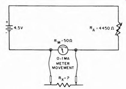
Fig. 4-4.
Note that for the shunt-type ohmmeter the greater the unknown resistance being measured the greater is the current through the meter.
For this reason the scale is such that the indicated resistance increases progressively from left to right, right being maximum for full-scale deflection of the meter. A typical shunt-type ohmmeter scale is shown in Fig. 4-5. Notice that the direction of increase of resistance is just the opposite of that for the series-type ohmmeter scale shown in Fig. 4-4.
4-5. Voltage-Divider or Potentiometer-Type Ohmmeter
With the series-type ohmmeter the scale tends to be overcrowded near the high resistance end. To reduce this crowding, and distribute the scale divisions a little more evenly, another type of circuit which uses the voltage-divider principle is used. The circuit is shown in Fig. 4-6. The meter is a high-resistance voltmeter and is connected across R, in series with RA, so it reads the voltage across Rs although it is calibrated in ohms. Rs is connected with the unknown resistance Rx so that the two form a voltage-divider across the battery. The voltage across Rs, indicated by the meter, depends upon how much resistance appears across the test prods. When the prods are shorted together the voltage across Rs is maximum, being equal to the full voltage of the battery, and RA is adjusted for full-scale meter deflection. The higher the unknown resistance R1 the lower the voltage across Rs and the lower the meter reading in current units. Thus, as is the case in the series-type ohmmeter, the highest resistance indications are at the left end of the scale. However, the scale divisions are somewhat more uniform than those of the series type.
4-6. High-Resistances and the Megger
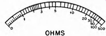
Fig. 4-5. Typical meter scale for shunt type ohmmeter.
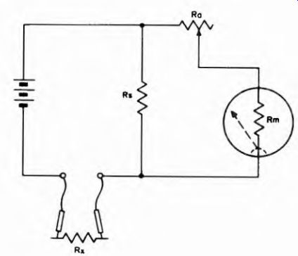
Fig. 4-6
Some instruments are available for measuring very high resistance values. They operate on the ohmmeter principle; the applied voltage is increased to a relatively high value so measurable currents can be produced through high resistances. These devices are known as "meggers." The megger is a portable insulation resistance test set for measuring extremely high values of electrical resistance, up to 100,000 megohms or more. Such high resistances are encountered during checking of the insulation resistance of cables, resistance between conductors of multiple cables, between windings and from winding to ground in transformers, between windings and from windings to ground in rotating equipment, and paper, mica, and ceramic dielectric capacitor leakage.
A typical megger and carrying case is shown in Fig. 4-7, the schematic diagram is Fig. 4-8. When the crank is operated, the d-c generator applies 500 v with the polarity indicated. Electron current flows from the negative terminal of the generator, through the potential coil, (which forms part of the ohmmeter movement), through the large resistor R2, and back to the positive terminal of the generator.
The magnetic field, set up by the potential coil, reacts with the field set up by the permanent magnet in such a way that the coil and pointer assembly move in a counterclockwise direction. With nothing connected between the terminals line and ground, the only current flowing is the current just described. As a result, the pointer indicates infinite resistance on the scale.
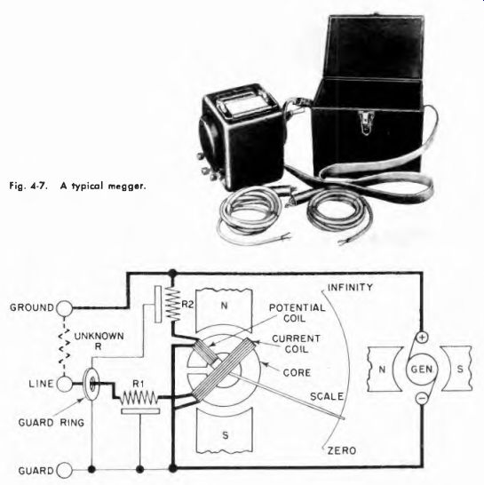
Fig. 4-7. A typical megger.
Fig. 4-8. Circuit of a typical megger. The metal guard ring and associated components prevent leakage currents along the surface of the instrument case when readings over 100 megohms are being made.
When an unknown resistance is connected between the line and ground terminals, the electron path is from the negative terminal of the generator, through the current coil (part of the ohmmeter movement) , through resistor R1, out of the line terminal, through the unknown resistance, into the ground terminal, then to the positive side of the generator. If the unknown resistance is extremely low, most of the current flows through the current coil and the pointer moves close to zero on the scale. If the value of the unknown resistance is increased, less current flows through the current coil with respect to the fixed amount of Current in the potential coil. Consequently, the pointer moves from zero toward infinity on the scale and indicates the resistance of the element or system connected between line and ground.