By itself, a meter movement has limited applications. Its resistance and current range may be appropriate for some special uses, more often for current measurement than for voltage measurement. Thus it becomes necessary to examine the basic capabilities of these meter movements as measuring devices, and to see how they may be adapted for a wide variety of practical applications.
3-1. Meters Are Basically Current Operated Devices
All meter movements which involve coils such as have been described are basically current operated devices. The meters function by virtue of the current which flows through the coil portion of the complete mechanism. Thus it would appear from both the d-c and a-c meters we have examined that the meter should be usable as a current measuring device by itself. However, since there is a maximum limitation in the amount of current which can be passed through the coil, there is a maximum current indicating range of the instrument when using the meter movement as is.
Based on the physical construction of the moving coil (d-c) and the moving vane (a-c) meter movements, greater limitations exist in the wire size used for the moving coil meter than for the moving vane variety, since the coil rotates in the former and heavy wire would unduly increase weight and inertia. Therefore, it is understandable that, when the coil alone is used without any auxiliary devices, the current measuring range of the d-c moving coil meter is very low. Yet we know that d-c current measurements embrace a great range, from a microampere up to thousands of amperes. How this is done will presently be explained.
The same is true of the a-c moving vane meter. While this type of mechanism permits heavier wire for the current carrying coil, since the coil is fixed in position, it too has limitations. However low and high values of alternating current are measured. So it stands to reason that some means is used in order to adapt the meter movements to the wide range of current measurements which must be made. The nature of this means is explained in this section.
3-2. Meter Coils Have Resistance
While it is true that the moving-coil and the moving-iron types of meters operate differently, both have one thing in common: both types make use of wire wound coils. They may not be the same in all meters but, whether the coils have few turns or many turns, each presents a certain amount of d-c resistance. For that matter the a-c meter coil also presents inductance to the a-c current, but this is generally so slight at the power frequencies to which these meters are applied that we can neglect the reactance of the coil.
At the moment we are not concerned with how much d-c resistance is present in the meter movement; all that matters is to bear in mind that it exists. The reasons are explained in subsequent paragraphs.
3-3. Meter Coils Are Subject to Voltage Drop
A meter movement presents resistance of some value to the flow of the current, therefore it stands to reason that a voltage drop will develop across the coil - a drop equal to the current times the resistance.
This voltage drop is very slight, but this is not the important point.
What is significant is that while we speak of the meter as being basically a current operated device, a current meter is also a voltmeter. It is a voltmeter of such range as corresponds to the maximum IR drop across the coil while the meter is indicating maximum current.
For example, suppose that we imagine a moving coil meter rated at 1 ma d-c maximum current and a coil (meter) resistance of 100 ohms dc. When the meter is indicating maximum current flow, a voltage drop equal to .001 x 100 or .1 volt (100 millivolts) appears across the meter coil. Hence it is a voltmeter with a maximum range of 100 millivolts, for it takes that much voltage to cause 1 milliampere of current to flow through the meter movement and so indicate full scale.
This situation is not limited to d-c meters only; it is just as true with the moving vane a-c meter. Every a-c current meter is therefore a voltmeter too, yet not in the practical sense. The reasons for this are the conditions which surround voltage measurement. Voltage measurements are made across the limits of a circuit, and the inherent resistance of the meter movement (dc or ac) is generally so low as to defeat every possibility of using the device as is, as a voltmeter. It must be "adapted" to measure voltage. As far as the meter is concerned, conditions in the instrument are exactly the same whether a voltage is applied or whether a voltage results from the flow of current. However, because the voltage present in a circuit where the full scale meter current flows far exceeds the permissible voltage drop across the meter, auxiliary means must be used to measure the circuit voltage, and yet keep the voltage drop across the meter at the proper value.
Thus while a basic meter movement, either ac or dc, appears in both current and voltage measuring devices, and may be used for the measurement of low values of current without any additions, the use of supplementary devices are required for voltage measurement.
3-4. Adapting Meter Movements for D-C Measurements
Measurable d-c quantities are current, voltage, and power. In this section we deal only with current and voltage; power is treated separately in Section 5. As to the measuring means, it is the permanent magnet moving-coil type of meter movement. The moving vane a-c meter also is usable for d-c measurements, but it is so seldom employed for this purpose that we ignore it here.
The moving-coil meter movement can be adapted to provide measurement of currents and voltages in excess of those measurable by the movement alone.
3-5. The Basic Principle of the Shunt
The current range of a basic meter movement can be increased by connecting the meter into a circuit in such manner that only a part of the total circuit current flows through the meter movement.
If the current through the meter bears some known proportionality to the total circuit current, the meter scale can be calibrated to show …
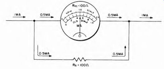
Fig. 3-1. How the current range of a meter is increased by addition of a shunt
resistor.
… the total circuit current corresponding to any value of current flowing through the meter.
In the case of moving-coil d-c meters, this is done by connecting an auxiliary resistor across the meter coil to act as a shunt path for some of the current. As in any parallel circuit, the current in the branches is inversely proportional to the resistance of the branches. By suitable design of the shunt around the meter, the current through the meter can be made any desired fraction of the total current flowing in the circuit where the meter is connected. This is illustrated for a single shunt in Fig. 3-1.
Assume a d-c meter rated at 1 ma maximum and a coil resistance of 100 ohms. If this meter movement is shunted by a 100-ohm resistor, half of the current will flow through the meter and half will flow through the shunt element. Immediately then the meter as a current indicator is capable of showing twice as much current flow as it can without the shunt, since 1 ma current flow in the circuit will result in only 0.5 ma through the meter, hence half-scale deflection. With a 1:1 ratio between the shunt resistance and the meter resistance, full scale indication on this meter would mean twice as much circuit current as is shown on the instrument.
If the shunt resistance is equal to one-half of the meter resistance, twice as much current will flow through the shunt as through the meter, hence the meter will carry only one third of the total current, and its maximum range of current indication has been increased threefold. By making the shunt equal to one-ninth of the meter resistance, nine times as much current will flow through the shunt as through the meter, so that the current indicating ability of the meter has been increased ten-fold.
By arranging a series of shunts which are selectable, the current indicating ability of a meter can be increased a thousand or more times its basic current carrying capacity, all the while keeping the full scale current through the meter within the original design figures. This is commonplace in many commercial meters. By suitable selection of the shunts controlled by a switch or a number of terminals, the current ranges can be multiplied in any desired steps. By proper selection of the multiplying factors, a single current scale serves several ranges, or more than one scale can be used. An example of these is given in Fig. 3-2. The switch must not be operated while current is flowing as this may burn out the meter. This is discussed further in Section 8.

Fig. 3-2. Example of multiple current scale.
Referring again to Fig. 3-1, the illustration of the meter face show's the addition of a new scale with 2-ma full scale indication in place of the original 1 ma. Such modification on a scale is not easy; a much more convenient arrangement is to select such shunts as enable the use of the original meter scale, multiplying the pointer indication by specific amounts as set by the shunt in use.
The practice of fabricating shunts for current meters is not recommended, except perhaps when the amount of resistance required is substantial, as for example an ohm or more. Because of the relatively low resistance of current meters, high multiplying ranges require very low resistance shunts. These necessitate accurate manufacturing processes.
Universal shunts are available as current range multipliers. These are usable with current meters of any coil resistance rating. They consist of a potentiometer arrangement as shown in Fig. 3-3, wherein the current range multiplying factor is a function of the ratio R/R1 and is independent of the meter resistance. If R/R1 is made equal to 1, 30, 100, 300, and 1,000 at the various switch positions, the current scale is increased by exactly the same amounts when the switch is in the respective positions. The initial requirement is that the total resistance R be such that when the switch is in position A (1), the meter read full scale. This can be accomplished by means of a supplementary variable resistance which shunts the whole divider. It is adjusted for full scale meter indication. It will not disturb the relative ratios as the switch position is advanced. The universal shunt is explained more fully in Sec. 8-3 in Section 8.
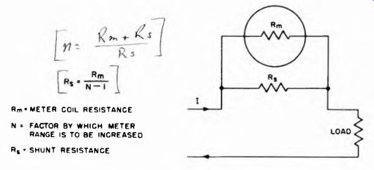
Fig. 3-4. Formula for calculating shunt resistors to increase the current
range of a basic meter movement. METER COIL RESISTANCE N = FACTOR BY WHICH
METER RANGE IS TO BE INCREASED Rs = SHUNT RESISTANCE
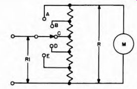
Fig. 3-3. Arrangement of Universal shunt.
It is interesting to note that most current meters of the moving coil variety contain internal shunts across the moving coil. In other words, the current carrying capacity of the basic meter movement itself is very low, and is increased to the required amount by means of a shunt, 'different shunts being used for meters of different current ratings. Generally moving coil meters of a certain general class are constructed alike, and are increased in current range as described above.
Moving vane a-c current meters are treated differently, as explained in Section 6.
3-6. Calculating Shunts
Although the construction of low resistance shunts for d-c meters is not recommended except when adequate facilities exist, Fig. 3-4 shows the equation used when a shunt is to be calculated. Assume a 50 microampere d-c meter with a coil resistance of 1,000 ohms. What should be the shunt connected across it to make it read 1 ampere full scale? Calculation shows that the current range must be increased 20,000 times, hence the shunt approximates 1/20,000 of 1,000 ohms. Substituting the accurate figures in the equation, it reads:
Rm = 1,000; N= 1/0.00005 = 20,000 R" = 20,000 - 1 ~ 0 05 ohm
As a convenience, if N is greater than 100 the numeral 1 in the denominator can be omitted, the error thus introduced is negligible for all cases other than when extreme accuracy is required.
3-7. The Basie Principle of the Voltage Multiplier
The voltage drop across a meter movement is fixed by its internal design. To make the device a voltmeter with a range higher than its own internal design establishes, it is necessary to make the instrument a part of a voltage divider system. A portion of the total applied voltage is dropped across the multiplier resistance and the remainder of the voltage is dropped across the meter movement. The latter voltage drop is of course never higher than planned for in the design of the meter.
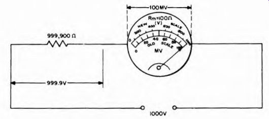
Fig. 3-5. How the voltage range of a meter movement may be increased by the
addition of multiplier resistors.
The multiplier circuit is simple. It consists of an external resistor in series with the meter as shown in Fig. 3-5. Assume a meter rated at 1 ma and a coil resistance of 100 ohms. The voltage drop across the movement is 0.001 x 100 or 0.1 volt (100 millivolts). To make this device capable of indicating 1,000 volts full scale requires that 1 milliampere of current flow through the meter when 1,000 volts are applied.
Regardless of how much voltage is applied to the system, the voltage across the meter must never exceed the product of the full scale current and the coil resistance, which in this instance is 0.1 volt.
To keep the current at 1 ma with 1,000 volts applied requires that the multiplier resistance must be E/I which is 1,000/0.001 or 1,000,000 ohms. However the meter has an internal resistance of 100 ohms, hence the multiplier resistance is 1,000,000 ohms less the 100 ohms meter resistance. Obviously the meter resistance in this case is so slight, relative to the required multiplier resistance, as to be negligible; thus we need not concern ourselves with it. However, for the sake of accuracy, let us assume that the multiplier is 999,900 ohms, in which case 999.9 volts will be dropped across the multiplier and 0.1 volt will be dropped across the meter, the sum of these two drops being 1,000 volts. The meter current will be 1 ma, and full scale indication then will correspond to 1,000 volts applied. The meter can then be so calibrated.
With a fixed ratio between the multiplier resistance and the meter resistance, any indication on the meter bears a fixed relation to the applied voltage. With 1 ma indication being the equivalent of 1,000 volts applied, a current indication of .2 ma then would correspond to:
-y- x 1,000 = 200 volts
With a direct proportionality existing between the current and the voltage for a certain multiplier resistance, the meter can be calibrated in terms of voltage rather than current, although it must be understood it is always the current through the coil which is causing the movement of the meter pointer. Thus, in Fig. 3-5 the old current scale of 0 to 1 ma is converted to a voltage scale from 0 to 1,000 volts; the .1 ma point on the old current scale corresponds to the 100 volt point on the new scale; the .2 ma point to 200 volts; the .3 ma point to 300 volts, etc., until the full scale position is reached.
In similar manner the use of a series of multipliers can change the 1 ma current meter into a multi-range voltmeter. For example, if the multiplier resistance in Fig. 3-5 is made 4,900 ohms then the total resistance of the system, which is meter resistance plus multiplier resistance, is 5,000 ohms. Since the current is limited to a maximum of 1 ma, the maximum voltage that can be applied is 5,000 x 0.001 or 5 volts, so the meter can be calibrated in voltage from 0 to 5 volts. Using this scale as the basis, the introduction of a different multiplier, say of 499,900 ohms (500,000 ohms in practice) instead of 5,000 ohms, or the addition of 494,900 ohms to the 5,000 ohms, makes the device a voltmeter with a maximum range of 500 volts, since 500,000 x 0.001- 500 volts. Using the precise value of 499,900 ohms for the multiplier and the 100 ohms in the meter, the total resistance is 500,000 ohms.
There is then a 499.9-volt drop across the multiplier and a .L volt drop across the meter movement.
Modern moving coil d-c voltmeters are developed this way; a current meter is operated in conjunction with multipliers. Three of the most common current ratings for meters used in this manner are: 1 ma, 50 microamperes, and 10 microamperes. Ohm's law shows that the lower the current rating of the meter for full-scale deflection, the higher must be the multiplier resistance for any given applied voltage; first, because the voltage drop is lower across the meter movement, and second, because the current permitted through the meter is less for full scale deflection. In comparison with the 1-ma meter for 1,000 volts applied, which requires a series multiplier of 1 megohm, the 50 microampere meter requires twenty times as much resistance or 20 megohms because the permissible maximum current is one-twentieth.
The use of multipliers in this manner is not limited to d-c moving coil meters only; it can be applied to moving vane meters, although the high current requirements of these meters sets a limit on the suitability of this means of increasing voltage scales. The potential transformer described in Section 5 is preferred. Where a-c voltmeters with minimum loading effect are needed, the moving coil meter operated in conjunction with a rectifier is used. This is discussed in Section 5.
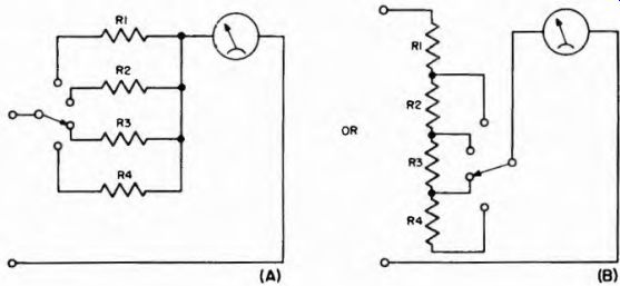
Fig. 3-6. Switch control of multi-range voltmeter amplifier (A) in individual
multipliers, (B) series connected multipliers.
Multi-range voltmeters using multipliers are generally arranged as in Fig. 3-6. Each switch position provides a new voltage range and, by suitable selection of the values for R1, R2, RI, and R4, one scale may be used for all ranges. For each range, the scale reading is simply multiplied by a factor appropriate to the multiplier for that range.
3-8. Total Voltmeter Resistance
For any one given meter with a fixed current rating, the higher the voltage range arranged for by the multiplier, the higher is the so-called total meter resistance. The resistance of the meter movement does not change, but the total resistance presented by the voltmeter and its multipliers increases as the voltage range increases. Thus, for the 1-ma meter previously mentioned, the 5-volt scale means a total resistance of 5,000 ohms; for the 100-volt scale it is 100,000 ohms; for the 500-volt scale it is 500,000 ohms; and for the 1,000-volt scale it is 1,000,000 ohms.
For the 50-microampere meter these total resistance values are 100,000 ohms, 2 megohms, 10 megohms, and 20 megohms respectively. For the 10-microampere meter they are 500,000 ohms, 10 megohms, 50 megohms, and 100 megohms respectively.
---------------
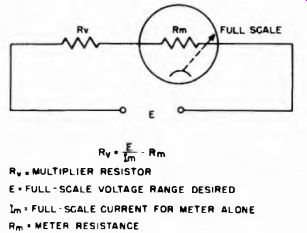
Fig. 3-7. Formula for calculating the proper multiplier resistance for increasing
the range of a voltmeter. As explained in the text, in many cases Rm con be
neglected in the formula.
Rv . multiplier resistor E« FULL-SCALE VOLTAGE RANGE DESIRED Im = FULL-SCALE CURRENT FOR METER ALONE Rm • METER RESISTANCE
----------------
As in the case of commercial direct current meters which are equipped with internal shunts, the voltmeters available on the commercial market already are equipped with internal multipliers. When they are not switch controlled, they are connected internally to the different voltage rated terminals of the meter. This does not prevent the addition of external multipliers to further increase the range of the instrument The calculation of the multiplier then is based on the additional voltage range required at the rated full scale meter current.
If the maximum range of a voltmeter is 1,000 volts and 2,000 volts is desired, the additional voltage drop required across a multiplier is 1,000. If the meter movement is rated at 1 ma, the external multiplier resistance required in series with the 1,000 volt terminal to raise the voltmeter range to 2,000 volts, is 1,000/0.001 or 1 megohm. For a 50 microampere meter it would be 20 megohms.
3-9. Calculating Multiplier Resistance Values
The equation in Fig. 3-7 enables calculation of the multiplier resistance required to adapt any current meter as a voltmeter. For example, if the meter is a 50-microampere instrument rated at a coil resistance of 1,000 ohms, and it is desired to convert it to a voltmeter to indicate 5,000 volts full scale, the following is a sample calculation:
E = 5,000 volts, Rm is 1,000 ohms and Im is 0.00005 ampere then Rv = 5,000 _ 100 000 000 ohms = 100 megohms
Obviously the meter movement resistance of 1,000 ohms is negligible when the multiplier resistance is so very much greater. If the multiplier resistance is at least 100 times the meter resistance, the latter can be neglected entirely.
The required voltage of 5,000 was deliberately chosen to illustrate that high voltage measurement requires the exercise of great caution if shock is to be avoided. Specially constructed multiplier units are required and must be well insulated and protected against moisture.
3-10. Accuracy and Ratings of Shunts and Multipliers
If the accuracy of a meter movement itself is from 2 to 5 percent, not much is gained by having the shunt or multiplier resistor accuracy better than 1 or 2 percent, since the maximum possible accuracy is that of the meter movement alone. However, if the meter is one of the especially accurate laboratory or comparison standard types, the auxiliary resistors must be precise in their values.
A variety of precision resistors are available for use as multipliers.
Some examples are shown in Fig. 3-8. They are available in accuracy ratings of ±1, ±1/2, ±1/4 and ±1/10 percent. Various power ratings of from 1/2 watt to 5 watts are also available.
Shunt and multiplier resistors must not only be accurate in their resistance values, but also must hold this accuracy for the life of the instrument with which they are used, in other words, indefinitely. For this reason they are usually ruggedly built and protected against the effects of moisture. If the elements are exposed to humidity the resistance value may be changed slightly. Since some resistors change value with different values of applied voltage, resistors chosen for multiplier use must have very low voltage coefficients so that they will change but negligible amounts during operation.
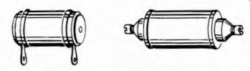
Fig. 3-8. Examples of precision resistors suitable for use as shunts or multipliers.
For most voltage measurements in electronic circuits, an accuracy of ±10 percent is adequate for servicing and general testing. For this reason, when special accuracy is not required, the owner of a meter may use less costly 5 or even 10 percent resistors for the multipliers.
3-11. Power Ratings of Shunts and Multipliers
Power ratings of shunts and multipliers must also be kept in mind.
For multipliers, the full-scale current must be within the dissipation rating of any multiplier used. Since power is PR, the amount of power dissipated for any voltage range is proportional to the resistance of the multiplier resistor. For example, in the case of the 1-ma meter movement the multiplier resistance should be 100,000 ohms for a 0-100 v scale. This resistor would have to carry 1 ma maximum. The power dissipated by this resistor then would be:
P = PR = (.001)2 x 100,000 = 0.1 watt
Thus, although the largest voltage scales may require 2-watt resistors, 1 watt sizes usually are sufficient.
For most meter movements the power ratings of shunts are very low when ranges below 10 or more amperes are encountered. For example, it was shown that the required shunt resistance to make a 50-p.a, 1,000-ohm meter read 1 amp full scale was 0.05 ohms. The current in the meter is negligible compared to the total current. The power dissipated in the shunt is thus:
P - PR ~ (1) 2 x 0.05 = 0.05 watt, or 50 milliwatts
3-12. Multipliers and Shunts for A-C Meters
It must be remembered that, if a meter multiplier is carrying alternating current, the inductance of the shunt as well as its resistance can be important. Hence it is advisable to use non-inductive elements such as resistors, although random wound, wire wound resistance coils are suitable if the resistance is relatively low, say less than 20,000 ohms. In view of the frequency limits (50-125 hz) imposed on moving-vane types of meters, the ordinary calculations as given for the d-c moving coil meters will be found suitable for these instruments, provided that the meter constants are those for the a-c meter on hand. As to the dynamometer type of instruments, shunts and multipliers should be secured from the original manufacturer of the meter. Further information for increasing the current and voltage ranges of a-c meters, including current and potential transformers, is given in Section 6.
It should be noted that the resistances for the lowest voltage ranges (up to 10 v) must be corrected by subtracting the resistance of the meter movement itself, which in these cases is an appreciable percentage of the total resistance.
3-13. Determining Unknown Scale Ranges
Occasionally a useful meter is obtainable, but without any accompanying information concerning it other than that it is de or ac. To adapt such a meter for use, certain facts must be determined, such as the internal resistance and maximum current range. Both of these factors can quite easily be determinable with a small amount of readily-available equipment. First, let us consider the maximum current range.
To determine the current range of a meter movement, sample currents are passed through it and the deflection noted. Full scale deflection is the desired condition. However, in obtaining full scale deflection, care must be exercised not to start with too much current and so overload, and possibly damage, the meter. Since the full scale current rating may be only a few microamperes, start with zero current and have some way of increasing the current uniformly so that it is always under control. Another current meter which is known to be accurate is required for comparison purposes. This second meter is connected in series with the meter whose scale range is to be determined.
Figure 3-9 shows the test circuit. Connect a 2-watt potentiometer (volume control) across a 1.5-v flashlight cell. A total resistance of anywhere from 50,000 to 100,000 ohms is suitable for R. The arm of the potentiometer (its movable tap) is then connected to the meters in series, then back to the low end of the potentiometer. If desired, a fuse may be added as shown, rated at about 50% over the comparison meter full scale reading. Before the meters are connected be sure the pot is adjusted all the way to zero voltage output. Then, make sure the polarity of the battery and the meters is consistent throughout, as shown in the figure. The pot arm is slowly advanced until the meters indicate, then continued until the unknown meter indicates full scale. The full-scale current rating of the unknown meter then equals the current indicated on the comparison meter. The comparison meter can be a current meter from a volt-ohm-milliammeter, and adjusted to different scales as the need arises.
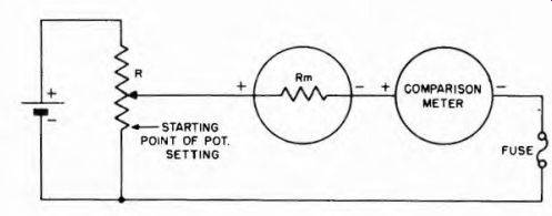
Fig. 3-9. Method of finding meter range by comparison with another meter known
to be accurate. Potentiometer R is used to limit the current to within the
range of the meters.
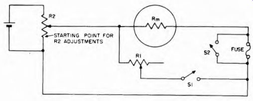
Fig. 3-10. Method for determining meter resistance.
3-14. Determining Meter Resistance
If a meter is of a standard make and model number, information as to current (or voltage) range and internal resistance is easily obtained from the manufacturer. If, however, this information is not available, as in the case of surplus meters, it is possible to determine it.
We have already explained how to determine the full scale current range of a meter for which the internal resistance is unknown. Now let us determine the internal resistance of the meter.
A method for measuring the internal resistance is shown in Fig. 3-10. A variable resistor R1 of value in the order of twice the resistance of the meter (this is of course a guess as to the meter resistance) is connected across the meter. A starting value can be 500 ohms. A switch S1 is connected in series with it to allow it to be removed from the circuit, although this can of course be done by simply disconnecting it.
A fuse is added for protection, and must be shorted out for final readings. The meter-jR7 parallel circuit is connected to a potentiometer A 2 (50,000 ohms) which is in turn connected across a flashlight cell (1.5 v) as shown. R2 must be turned down to give zero voltage (bottom of resistor on this diagram) before the meter is connected.
First, R1 is removed from the circuit and R2 is adjusted for full-scale deflection. Then R2 is left set while R1 is connected into the circuit and adjusted for half-scale deflection. When this has been done, R1 has the value equal to the meter resistance, which can be determined by measuring Rl or reading its calibration if it is a calibrated resistor.
If only a small part of R1 is used, measurement may be critical. This means that R1 is too high in ohmic value, and a lower value is needed.
The theory behind this method is that when the meter deflection is reduced to half scale, the current must be dividing equally between the meter and R1, so R1 must be equal to meter resistance. Rm and R1 are so small compared to R2 that the assumption that the same total current flows with or without R1 is valid.
3-15. Ohms-Per-Volt Sensitivity
In Section 1 it was pointed out how some basic meter movements have different full-scale current ratings than others. Meter movements with the lowest full-scale current ratings are referred to as the most "sensitive," because they respond most to the smallest current values.
When a meter is used as a voltmeter another method is used to designate sensitivity, although it actually indicates the same kind of thing. In this method, a meter is said to have so many "ohms-per-volt." This applies both to the meter movement as well as to its combination with any multiplier resistor.
For example, consider the meter of Fig. 3-5. As shown there, the meter movement alone reads 100 mv full scale, and has a resistance of 100 ohms. The ohms-per-volt is found by dividing the resistance in ohms by the full scale internal voltage drop in volts. Thus:
Ohms-per-volt - = 1,000 ohms per volt
Actually the ohms-per-volt sensitivity depends only upon the full-scale current reading of the instrument alone, and not upon its resistance, as can be seen by trying the above calculation for a 1-ma movement of various other resistances, remembering that the full-scale voltage rating also changes with resistance in each case.
Ohms-per-volt sensitivity also is the reciprocal of the full-scale sensitivity in terms of current. In other words, the full-scale current rating in amperes divided into 1 gives the ohms-per-volt for the meter movement. In the case of the 1-ma meter above, the ohms-per-volt sensitivity is 1 divided by one-thousandth of an ampere. Thus:
Ohms-per-volt = Full scale current in amperes - * = 1,000
Let's return to Fig. 3-5 and check the other ranges to see that the ohms-per-volt rating of a meter remains the same no matter what multipliers are used. If the full-scale voltage is 1,000 volts and the total resistance is 1,000,000 ohms, the ohms-per-volt rating is 1,000,000/1,000- 1,000. If the full-scale voltage is 10 volts and the total resistance is 10,000 ohms, the ohms-per-volt rating is 10,000/10 - 1,000.
It becomes clear, then, that no matter what multiplier resistance is used, the same meter movement still has the same ohms-per-volt sensitivity rating. The lower the full-scale current rating of a meter the higher its ohms-per-volt rating.
Why are we so much interested in ohms-per-volt sensitivity? Because if a voltmeter resistance is too low, it may load a high impedance circuit and cause error in the voltage reading. By means of the ohms-per-volt sensitivity it is possible to calculate the total resistance of a volt meter when set to a given scale, and thus know how likely it is to load the circuit in which the measurements are being made.
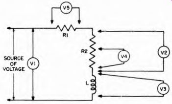
Fig. 3-11
3-16. Voltage Measurement
Voltmeters whether d-c or a-c always are connected across the circuit, between the two points where the voltage is to be measured. This is shown in Fig. 3-11, and it is to be noted that the kind ol voltage applied to the circuit is omitted. The reason for this is that the fundamental requirement stated above applies to all sorts of voltage, and is independent of the nature of the circuit.
Concerning Fig. 3-11, meter 1 measures the total voltage being applied to the circuit; meter 2 measures the voltage drop across R2; meter 3 measures the voltage drop across L; meter 4 measures the voltage drop across a portion of R2 and meter 5 measures the voltage drop across RI. The voltage measurement across L warrants several remarks.
If the applied voltage is a-c, then the voltage measured across L is the IZ drop at the frequency of the applied a-c voltage, which of course assumes that the voltmeter is capable of response at that frequency. On the other hand, if the applied voltage is de the voltage drop across L is the IR drop, where R is the d-c resistance of the winding and I is the current through the winding.
Whether or not a voltmeter is capable of measuring the IZ drop across a circuit element subjected to an a-c voltage depends entirely on the design of the measuring device. Suitable instruments are discussed in this guide, but in the meantime a very pertinent detail concerning voltage measurement warrants comment. This is the ohms-per-volt rating of the voltmeter relative to its loading effect on the circuit under test.
3-17. Loading Effect of the Voltmeter Resistance
The effect of Voltmeter resistance on a high-resistance circuit may be appreciated from a study of Fig. 3-12A, 3-12B and 3-12C. In Fig. 3-12A, the resistors R1 and R2 are shown shunted across a 100-volt battery. Since R1 and R2 are equal in resistance, the voltage divides equally across them; and since the total voltage is 100, the voltage across each resistor is 50 volts.
When a voltmeter is connected across R2, as shown in Fig. 3-12B, the circuit then becomes effectively that shown in Fig. 3-12C, in which the voltmeter is represented as the resistance Rm. Assume that we are using a d-c voltmeter with a rating of 1,000 ohms-per-volt on the 100-volt scale, its resistance is 100,000 ohms. Since Rm is in parallel with R2, and Rm = R2, the effective resistance when the meter is across R2 then becomes 50,000 ohms, just one-half that existing without the meter.
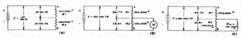
Fig. 3-12 (A). Effect of voltmeter resistance on circuit resistance.
Fig. 3-12 (B). When one of the resistors of Fig. 3-12A is shunted by a voltmeter, its resistance together with that of the voltmeter forms a parallel circuit across which the voltage drop is lower than formerly.
Fig. 3-12 (C). In this schematic the resistance Rm of the voltmeter is shown shunted across R2, which is the equivalent circuit of Fig. 3-12B, and shows how the voltage drops across RI and R2 are changed from those shown in Fig. 3-12A.
(C)
The total circuit resistance betwe7en A and B is now no longer 200,000 ohms, but 150,000 ohms; and the voltage across R2 and the meter will be equal to the ratio of 50,000 ohms (representing the resistance of R2 and the meter in parallel) to the total circuit resistance of 150,000 ohms. Therefore, only one-third the total voltage E across the circuit will be indicated by the meter. So, instead of being 50 volts, the loading effect of the meter has reduced the voltage to one-third of 100 volts or 33| volts. This means that the error in reading amounts to 16-2/3 volts, which corresponds to 33| percent less than the true voltage when the meter is disconnected from the circuit.
It is easily seen from this illustration that the error in reading due to loading effect in high-resistance circuits can be far greater than meter inaccuracies due to manufacturing causes. For this reason it is imperative to use a voltmeter of high resistance rating in high-resistance circuits.
Suppose for the moment that the meter has an ohms-per-volt rating of 20,000, in which case the 100-volt scale presents a total meter resistance of 2,000,000 ohms. Placing this resistance across R2 in Fig. 3-12A, results in a final value of 100,000 4- 2,000,000 100,000 x 2,000,000 = 95,200 ohms
The total circuit resistance then becomes R1 4- (R2 in parallel with Rm) or 195,200 ohms. The voltage across R2 then is:
= 48.7 volts or within 3 percent of the correct value.
The advantage of the higher ohms-per-volt rating is evident. This is even more important as the circuit resistance becomes higher and the circuit voltage becomes lower.
Although the examples cited in Fig. 3-12 are based on d-c voltages, the same condition applies to a-c circuits; the voltmeter resistance must be high in comparison with the resistance of the circuit across which the voltage measurement is made. As to what is meant b a high ratio between voltmeter and circuit resistance, a suitable minimum is about 20:1, preferably higher. As much as it may be desired this cannot always be realized, in which event the error may be more than a few percent and will have to be tolerated. The important thing is to realize the possibility of circuit loading when the voltmeter is applied. The subject also receives attention elsewhere in this guide.
It is in the area of sensitivity that the permanent-magnet moving-coil meter movement shows its great superiority over a-c/d-c movements, such as moving-iron types and dynamometers, for measurements in electronic circuits. The sensitivity of these latter movements is relatively very low, ranging from 1 to 300 ohms per volt, depending upon the range and type. The sensitivity is lowest in these instruments for the lowest voltage ranges, a 2-v meter sometimes drawing as much as 0.5 amp for full-scale deflection. Obviously, the usefulness of these meters in electronic circuits is limited to measurement of power line voltage and current, filament (heater) voltage and current, and the like. Of course the dynamometer is very useful in the form of a wattmeter for servicing radio and tv receivers, communication receivers and other devices, as explained in Section 4.
3-18. Current Measurements
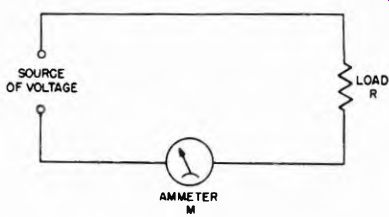
Fig. 3-13. For current readings, the meter should always be connected in series
with the load whose current is to be indicated, as shown here.
Whether ac or dc, when current measurements are made, one significant condition must be borne in mind. Irrespective of the type of current meter used, the instrument always must be connected in series with the circuit where the current is to be measured. In this way the current flowing in the circuit will flow through the meter This is shown in Fig. 3-13, where M is the meter and R is the load. The fact that the load is shown as a resistance does not limit the circuit arrangement to resistances. The load may take any form: it may be a lamp or a vacuum-tube filament; it may be a d-c or a-c motor; it may be the plate, screen, or cathode circuit of a vacuum tube; it may be a transformer winding; in fact it may be anything through which current flows. The type of meter used is, of course, determined by the character of the current, its magnitude, its waveform and the accuracy of measurement required. Very low-current meters with high movement resistance are used in a similar manner. The high resistance of the meter seldom disturbs the circuit to which it is added because low- current circuits usually are of very high resistance.
In the event that the circuit has a number of branches, measurement of the current in each of the branches calls for the use of a meter in each branch; and measurement of the total current requires the use of a meter in that conductor of the complete circuit which is common to all the individual branches. A simple example of this is shown in
Fig. 3-14 wherein meter Ml measures the total current, meter M2 measures the current flow in the R1 branch and meter M3 indicates the current in the branch containing the series combination of L and R2.
One point, or one lead, in the circuit in which measurements are to be made is nearly always grounded, although this need not be so.
Various potentials may then exist at other points in the circuit with respect to ground. If a current is to be measured, the ammeter should be inserted at the lowest potential point with respect to ground.
For example, in Fig. 3-14, if the lower side of the source of voltage is grounded as shown, the total current should be read with the meter in the position M1 rather than in the lead from the top of the voltage source, (shown by dotted line meter M1), where the potential is high.
Similarly, in the branch circuits, M2 and M3 are properly connected as shown by the solid line drawings instead of above R1 and R2 respectively, as shown by the dotted line drawings.
3-19. Effect of Adding Current Meter to Circuit
Adding a current meter in series with a circuit is the equivalent of adding resistance and inductance in series with the circuit. In a d-c circuit the inductance of the meter coil is unimportant. In the a-c circuit-operated power frequencies, the same can be said to be true.
However, in both cases, the resistance of the meter coil can be important because it tends to reduce the current in the circuit being measured. Whether the amount of reduction is significant depends entirely upon the original circuit resistance without the meter in place, and the circuit resistance with the meter connected into the circuit.
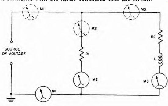
Fig. 3-14. This circuit shows how an ammeter can be connected in series with
any branch of a circuit to indicate the current in a particular branch, or
in the supply lead for the total current in the branches. Meter M1 measures
the total current; M2 measures the current through R1, and M3 measures the
current through R2 and 1.

Fig. 3-15. This formula is used to find how much the ammeter will read low
due to the resistance of the meter in the circuit.
PERCENT DECREASE INCURRENT
'Rc + r,"'100 Rm' METER RESISTANCE Rc' CIRCUIT RESISTANCE WITHOUT METER
Moving-coil d-c meters present low coil resistance whereas the moving-vane a-c meters present higher values of resistance. However, if the original circuit resistance, without the meter in place to measure the current, is at least 100 times the meter movement resistance, this effect of the meter is negligible. Reducing the ratio to 50 makes the measured current about 2 percent lower than the true current without the meter in the circuit. This much difference is not too high, but it is possible that the difference may become appreciable depending on the circuit resistance and the meter resistance. The equation shown in Fig. 3-15 enables determination of the percentage decrease in current indication due to the presence of the meter. For example, if the circuit resistance is 2 ohms and the meter resistance is .05 ohm the indicated current will be low by:
. 05 /2 + .05 x 100 = 2.4 percent