8-1. Multi-Range Meters
A multi-range meter is a meter movement extended to include two or more ranges. A multi-range meter is distinguished from a volt-ohm milliammeter (covered later in this section) in that it measures only one of the basic quantities: current, voltage, or resistance.
The multi-range instrument is in a class by itself in that it is a general utility test instrument. In terms of sensitivity, for example, the d-c voltmeters are in the 1,000 ohms-per-volt class. The alternating- current meters are intended for use at 50-60 hz. The a-c voltmeters are rectifier type instruments in some cases and ordinary moving-vane types in others. Hence the former have a-f applications whereas the latter are intended for 50-60 hz work.
Although these devices find some application in electronic circuits, their sensitivity limits their use. Portability, small size and low cost are their main features.
Some examples of these instruments appear in Fig. 8-1. Two methods are used for changing from one range to another. One method is to have separate terminals for each range, with one terminal common to all. These are evident in Fig. 8-1 A, and will be found on most high current meters, whether a-c or d-c measuring types.
The second method is to use a selector switch. This is commonly done on voltmeters, ohmmeters, and very low current meters. The switch arrangement also is seen in Fig. 8-1B. The difference in range selecting means stems from the effects of resistance in these arrangements. Because devices measuring voltage and very low current are relatively high resistance units, the contact resistance at the switch terminals is of limited importance. However, in the high current devices it would be important, hence a terminal form of connection is provided.
TRIPLETT MODEL 625 (A) WESTON MODEL 540 (B)
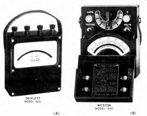
Fig. 8-1. Photos of mufti-range instruments with terminals and with switch
selector. (A) Triplett, (B) Weston.
8-2. Multi-Range Direct-Current Meters
In small portable instruments of the type shown in Fig. 8-1, the meter movements may be as sensitive as 50-microamperes full scale to as high as 200 microamperes, depending on the ranges provided in the device. The multiple functions relative to range are provided by shunts.
The switch controlled ranges should not be selected with the current flowing through the meter. The reason for this is that there are usually no shorting switches in a range selector. It is thus possible for the shunt to be momentarily disconnected as the range switch is being manipulated. The circuit current then flows through the basic meter movement coil and, if excessive, can burn out the coil.
Under the circumstances, it is advisable to shut off the flow of current momentarily when switching meter ranges.
_ R Rm r - N r=PART OF R TOBE SHUNTED ACROSS MEASURED SOURCE R=TOTAL SHUNT RESISTANCE Rm = METER RESISTANCE N = MULTIPLYING FACTOR
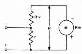
Fig. 8-2. The universal
shunt and applicable equation.
It is interesting to note that low-current measuring meters are usable as voltmeters by connecting external multipliers in series with the lowest current ranges. In this way the current rating which is used to determine the ohmmic value of the multiplier is the current rating of the range being used. Thus, if the multi-range meter is a microammeter and the lowest current range is 0-50 microamperes, the device can be made into a 20,000 ohms-per-volt voltmeter by using that range.
If the instrument is a milliammeter and the lowest current range is 0-1 milliampere, the device can be made into a 1,000 ohms-per-volt voltmeter. A two-gang switch is employed.
8-3. The Universal Shunt
A type of shunt which has come into wide use in conjunction with small, portable, multi-range meters is known as the universal shunt, also called the ring shunt, or Ayrton shunt. It is readily adaptable for use with meters having different values of internal resistance.
As shown in Fig. 8-2, the resistors in the universal shunt are either connected in series or a single tapped resistor is employed which is shunted across the meter. The resistance of r for any desired factor N, by which the full-scale range of the meter is to be multiplied, is determined by the formula in Fig. 8-2. If the total shunt resistance R is 100 ohms and the internal resistance of the meter R,„ is 20 ohms, to increase its current range 10 times the selection of r by means of the top is such that the resistance of r is 100 + 20 .
r = g- = 12 ohms
If an additional range representing 100 times the full-scale range of the un-shunted meter is desired, under the same conditions 100 + 20 .
r - -----joy =1.2 ohms
The values of the universal shunt shown in Fig. 8-3 are the exact figures required to multiply the range of a 500 microampere meter 2, 20, 200, 2,000, and 10,000 times. Since the meter resistance is 100 ohms, and it is desired to have a 1-milliampere range, it follows that the total shunt resistance must be equal to 100 ohms. When the switch is in the 1-ma position, half the current goes through the total shunt resistance and the other half goes through the meter. The value of each of the shunt resistors is calculated in accordance with the equation in Fig. 8-2. Note that on the 100-ma range, for example, the operative shunt resistance, r, is equal to the sum of r3, r4, and r5. A similar situation holds for the other ranges.
8-4. Multi-Range Alternating-Current Meters
The small portable multi-range alternating-current measuring meter resembles those shown in Fig. 8-1, particularly the one with terminal connections. The multiple ranges, whether in milliamperes or in amperes, usually are arranged by means of self-contained current transformers. An example of this appears in Fig. 8-4. This is an inside view of a commercial current meter of the small portable variety. The circuitry of the system controlling the ranges for one device is symbolized in Fig. 8-5. This is an elaboration of Fig. 6-10.
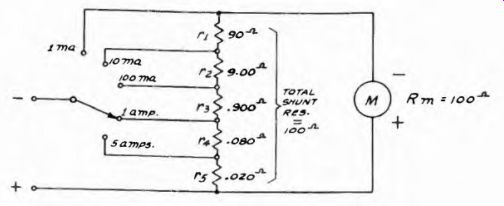
Fig. 8-3. A universal shunt operated by means of a single-gang switch.
It is interesting to note that the taps are located in the primary winding, with terminal A being common to both primary and secondary circuits. To measure alternating currents up to 1 ampere, the secondary S acts as a shunt on the meter and the secondary winding is in the current path. For higher values of current, the free lead is moved to different primary taps, thus changing the current transformation ratio between the primary and secondary circuits.
8-5. Multi-Range Voltmeters
Multi-range voltmeters are created by adding series resistance of the proper value to a basic meter movement. The additional ranges can be provided by having different multiplier resistors available to be switched into the circuit as desired. A simple arrangement for selecting multipliers is shown in Fig. 8-6. The switch selects a multiplier resistor and places it in the circuit, thus providing a voltmeter range.
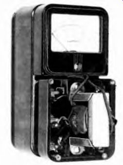
Fig. 8-4. Internal view of Simpson a-c current meter with current transformer.
A more frequently used arrangement is that of Fig. 8-7, in which all the multiplier resistors are in series across the meter. The external operation of the switch is the same as in Fig. 8-6. In either case, the values of the various multiplier resistors are calculated in the same manner as explained in Section 3. The values of the resistors in Fig. 8-7 are correct for a 1,000 ohms-per-volt, or 1-ma, meter movement whose resistance is 50 ohms. Virtually all small multi-range d-c voltmeters are 1,000 ohms-per-volt.
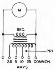
Fig. 8-5. Circuit of multi-range a-c ammeter with tapped current transformer.
In the a-c instrument, the arrangement is similar to that of Fig. 8-8.
Metallic rectifiers are used and the meter is shunted down by R, so its effective sensitivity is 1,000 ohms-per-volt (explained in Section 3) . Thus, for example, between the 1,000-v and the 250-v taps there is a resistance of 750,000 ohms. Since the voltage difference is 750 v, the sensitivity is 1,000 ohms-per-volt.
Rs must be about 10.5 ohms to shunt the 50-^a meter for an effective sensitivity of 1,000 ohms-per-volt. The value of Rv must be such that, added to the value of resistance of the rectifier, the total will be the correct multiplier for 2.5 v, or 2,500 ohms. In practice, R, and Rv ...
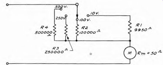
Fig. 8-6. Simple switching system for selecting multi-range voltmeter multipliers.
... are wirewound resistors whose exact value is adjusted for the individual rectifier when the meter is calibrated.
Note how the 5,000-v scale "hot" terminal is brought out separately.
The selector switch must be on the 1,000-v position for correct 5,000-v readings, since the required 5-megohm resistance can be obtained only by adding all the multiplier resistors in series with the 4-megohm resistor.
8-6. Multi-Range Ohmmeters
Ohmmeters also are available as separate, portable multi-range instruments. In appearance they resemble those shown in Fig. 8-1; the different ranges are switch controlled. Ohmmeter ranges are changed by adding multipliers or shunts to the series-type circuits and also shunts, depending on the individual design. In most instances a single ohms scale calibration is used and the range switch is calibrated in multiplying factors, such as R X 1, R X 10, R X 100 etc.
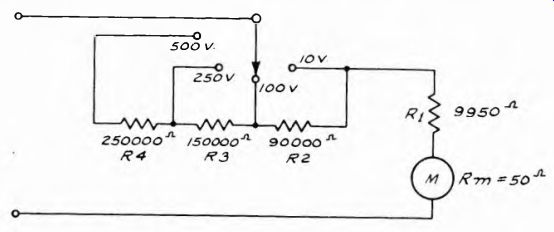
Fig. 8-7. Switching system for series connected voltmeter multipliers, using
50 u-a meter for 500-volt maximum scale.
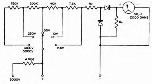
Fig. 8-8. Multiplier arrangement for a multi-range a-c voltmeter.
8-7. Multi-Range D-C Voltage Current and Ohmmeter
This is not a commonplace commercial device, but rather a military unit that warrants comment. The circuit is shown in Fig. 8-9. It is a very simple device with a universal shunt for the a-c current ranges; simple series multipliers for the voltage ranges, and a dual-range series type ohmmeter for resistance measurement. One value of voltage is used for one resistance range and a higher value for the second resistance range.
8-8. Volt-Ohm-Milliammeter (VOM)
These devices are multi-range instruments, but in addition are multi function too in that they measure alternating and direct current and d-c resistance. Examples of the devices appear in Fig. 8-10.
As can be seen, two physical varieties are available: the small units which resemble the multi-range instruments of Fig. 8-1, and units that...
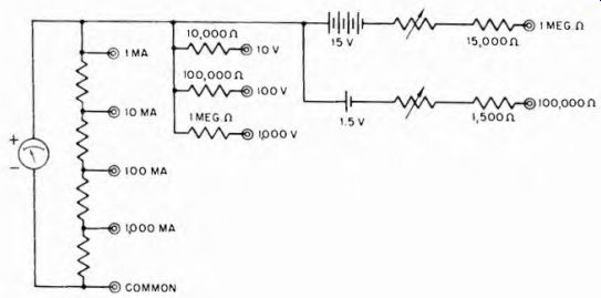
Fig. 8-9.
Circuit of combination multi-range d-c voltmeter and current meter used by
Armed Forces.
...are large physically. Two other differences are found between these groups: the sensitivity of the device relative to its ohms-per-volt rating, and the number of ranges afforded for each function.
Both groups of instruments use d-c moving-coil meters, with metallic rectifiers for a-c measurements. However the smaller and less costly units generally have sensitivity limited to 1,000 ohms-per-volt for both ac and dc, whereas the larger ones afford as high as 20,000 ohms-per-volt sensitivity for de and up to 5,000 or 10,000 ohms-per-volt for a-c scales.
In all other respects these VOMs are combinations of multi-range meter systems, with one meter being used as the indicator for all functions. Having described the means of adapting meters for d-c and a-c measurements, it is unnecessary to repeat the processes as found in VOMs.
SIMPSON MODEL 260
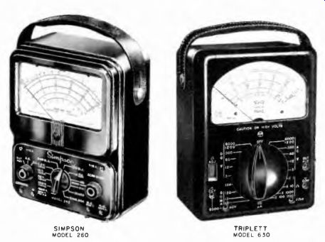
Fig. 8-10. Photos of Simpson model 260 and Triplett model 630 multi-range
and multi-function VOMs.
TRIPLETT MODEL 630
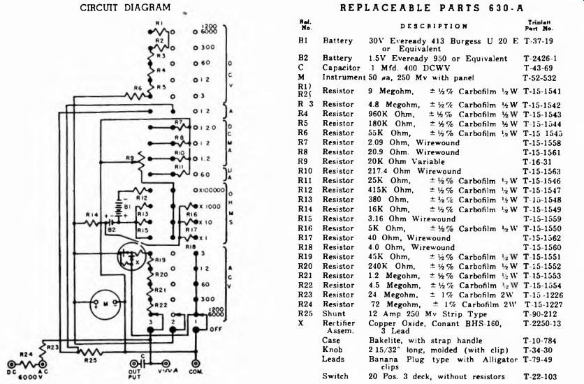
Fig. 8-11. Schematic of Triplett Model 630A VOM. CIRCUIT DIAGRAM REPLACEABLE
PARTS 630-A
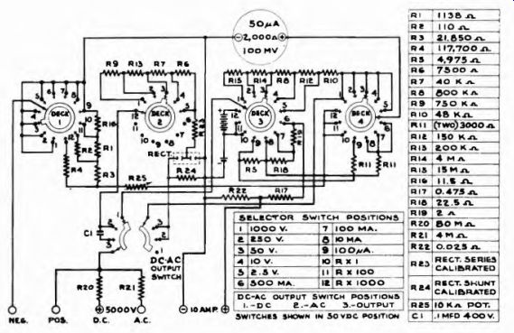
Fig. 8-12. Schematic of Simpson model 260 VOM.
Inasmuch as the section on applications of meters deals with the manner of using VOMs, and descriptions of the devices are included, it should suffice here to show circuits of two different brands of VOMs.
These appear in Figs. 8-11 and 8-12.
Control of the functions and ranges is by means of a rotary switch, and connection to the instrument is via banana-plug jacks or phone-tip jacks. The selector switch has several decks by means of which the circuit is varied to suit the measurement. Referring for a moment to the two VOMs shown in Figs. 8-11 and 8-12, the d-c voltmeter circuit uses a tapped series multiplier typified by Fig. 8-7. The 5,000-volt range has a separate multiplier resistor which is placed in the circuit when the selector switch is in the 1,000 volt position and the test lead is in the 5,000-volt pin jack.
The a-c voltmeter circuit is symbolized by Fig. 8-8; the description that accompanies this figure is a representation of the system used in the device. The ohmmeter circuit is a combination of the shunt and series methods, with different voltage values for the low and high resistance ranges. The direct-current ranges use the universal shunt.
8-9. VOM Scales
A typical VOM instrument scale is shown in Fig. 8-13. Two separate ohms scales are used; the upper one for a series type ohmmeter for high values, and the lower scale is for a shunt type circuit for low values of resistance. As can be seen, these two scales read in opposite directions, for reasons already explained in Section 4.
Two scales are provided for voltage measurement, one for a-c volts and the other for d-c volts. However only one series of numbers are used as calibrations. To make it convenient to use the single set of calibration numbers for both a-c and d-c measurements, the corresponding voltage points are joined at the main divisions. The sub-divisions are read in similar manner on both scales.
The basic scale is divided into .2 volt steps with the major divisions being whole number values. The fundamental scale is from 0 to 10 volts.
The multipliers increase the range in steps of 5 and 25. The upper scale is read for a-c, and the lower scale is read for d-c, using the same numbers for both.
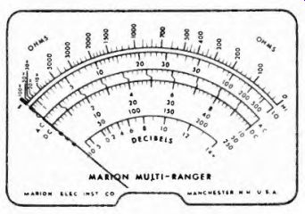
Fig. 8-13. View of Marion multi-range VOM scale.
The direct-current scale is the a-c voltage scale with 10-volts d-c corresponding to 1 ma for one setting of the current range switch and 10 ma for another setting. Similarly, the 50-volt range corresponds to 50-ma and 500-ma full scale respectively. Hence, in one case, the scale calibration is divided by 10, and, in the other case, is multiplied by 10.
Still another scale is used for the db range. By projecting the 0-db point upward to the a-c voltage scale we see that it corresponds to 1.73- volts rms, thus indicating that this scale is for db above or below a reference level of 6 milliwatts into 500 ohms. This is explained more fully in Section 6.
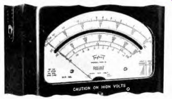
Fig.
8-14. View of scale on Triplett Model 630A VOM.
Another version of a VOM scale is shown in Fig. 8-14. Here only one ohmmeter scale is used and the range selector has calibrated positions for resistance and resistance-multiplying factors. Individual scales are provided for d e and a c voltages. In addition a separate 0-3 volt rms a c scale is furnished for low voltage measurements. In other brands of VOMs this scale may be 2.5-volts rms With only three a-c voltage ranges calibrated directly, higher and lower values require the application of multiplying factors or dividing factors as determined by the range selector switch position. Thus to read 600 volts maximum the 60 volt scale is used and multiplied by 10; to read 6,000 volts the same scale is multiplied by 100. This procedure applies to both the d-c and the a-c scales.
8-10. Extending DB Scales
The db scale is derived with the meter used as an a-c voltmeter, the only difference being that the db scale is used. Ordinarily, the db scale can be read directly when the selector is set for the lowest a-c voltage range. This reading can always be checked by comparing the 0-db point with the reading on the a-c voltage scale. It is 1.73 volts rms in Figs. 8-10 through 8-14. Frequently this comparison is the only way to determine which voltage scale is to be used for direct db readings.
The same higher scales used for a-c voltage readings are also used for db. For db, however, instead of multiplying all direct-scale readings by some power of 10, we add the correct number of db. This is in line with the fact that when numbers are multiplied the logarithms of the numbers are added to obtain the logarithm of the product. Suppose, when reading db, the scale indicates plus 8 db, but the selector switch is set for a voltage scale 100 times the basic scale upon which the db scale is based. 100 times voltage is 40 db (see Section 6 for method of calculation). Therefore we must add 40 db to the indication on the db scale with the selector in that position. In this case the reading will be 8 plus 40 or 48 db.
If the original db reading is negative, the algebraic sum is used.
Suppose the meter range selector is set for a scale 10 times the basic voltage scale and that the indication is minus 5 db. Then, 10 times voltage is 20 db, therefore the indicated level is minus 5 plus 20, or plus 15 db.