5-1. Measuring Power in D-C Circuits
In d-c circuits, and in a-c circuits where the components are pure resistances, power is equal to the current times the voltage and thus may be determined by measurements of voltage and current in the circuit under test. Since voltage and current are related by Ohm's law to resistance, power may also be determined by measurements of resistance and either current or voltage. The various power relationships which exist in d-c circuits are expressed in Fig. 5-1.
Thus, in Fig. 5-2, if the voltmeter reads 12 volts and the ammeter indicates a current of 1 ampere, the power in the load circuit, RL, is 12 x 1 or 12 watts. If we know that the resistance of the load is 12 ohms and the current is 1 ampere, then the power is I2 x 12 or 12 watts. If the voltage is 12 volts and the resistance is 12 ohms, the power is:
122/12 = 144/12 = 12 watts.
It seems quite simple to connect a voltmeter across a circuit and an ammeter in series with a circuit to determine both the current and voltage in the circuit. However, there are certain considerations which must be observed, in making these connections, otherwise the measurements may be considerably in error.
Figure 5-2 illustrates the above statement. If the resistance of the voltmeter is high its manner of connection is not of much importance; but since it is possible that the voltmeter resistance might be low and its current consumption appreciable, mention must be made of the fact that if the voltmeter is connected into the circuit as shown in Fig. 5-2 that the load current as indicated by the ammeter is the sum of the current drawn by the voltmeter and the load resistance.
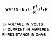
Fig. 5-1. The power in a circuit can be calculated by knowing the resistance
and either the current or voltage in accordance with the formula on the left
r2
This load current would be greater than that found in the circuit of Fig. 5-2 for identical meters and load resistance, and would represent an error in power consumption indication.
5-2. Measuring Power in A-C Circuits
In a-c circuits, power is not always equal to "voltage times current.'' It is equal to voltage times current only when the circuit is purely resistive and there is no reactance present. When reactance is present (inductance or capacitance) it influences the current or voltage but absorbs no power. A pure reactance alternately stores energy and returns it to the circuit; the amount absorbed equals the amount given up so that the consumed power is zero. In this case (pure reactance) the voltage and current are 90° out of phase with each other. If (as is more common) there is some reactance and some resistance in tire circuit, the power consumed is less than voltage times current (E1) but is more than zero. If the power factor of the circuit is known, the power can be determined from the voltage and current readings by the following formula:
Where P = EI (pf)
P is the actual power consumed E is the a-c voltage across the load I is the alternating current through the load pf is the power factor The power factor expresses the relative amount of resistance in the circuit compared to total impedance.
Thus , R pf - f = cos e
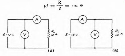
Fig. 5-2 If the ammeter A is connected as shown in A at the left, only the
current drawn by the load RL will be indicated on it; if it is connected as
in B, right, then the ammeter reading will be the current drawn by both the
load and the voltmeter, V.
... where R is the resistance of the circuit Z is the total impedance of the circuit e is the phase angle between current and voltage In order to measure accurately the power in any a-c circuit, we must have some instrument which takes into account the power factor as well as the current and voltage. Such an instrument is the wattmeter.
However, in practice, many power readings are simplified because: (a) the voltage is reasonably constant, and (b) the power factor is reasonably close to 1.0. This is true of most electrical appliances in the home, where the power line voltage is standardized at 117 v and 60 hz. Such appliances as ranges, heating pads, broilers, heaters, coffee
makers and the like are simply pure resistors connected across the line. Motor-driven devices, such as vacuum cleaners, hair-dryers, pumps, sewing machines etc., have a power factor only slightly less than 1.
Power transformers used in television and radio receivers have a power factor between .9 and .95.
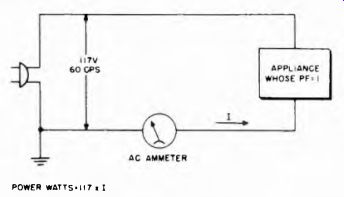
Fig. 5-3. Diagram of arrangement which measures power with an ammeter providing
the voltage is constant and the power factor of the load is 1.
Because of constant known voltage and unity power factor, satisfactory approximations of power readings can be made simply by connecting an a-c ammeter in series with the grounded lead, as shown in Fig. 5-3. The power is then equal to the voltage (117 v in this case) times the current (as indicated by the current meter). Sometimes ammeters are calibrated in terms ol power, assuming a specified voltage and unity power factor. As long as these conditions exist, and to the degree which they exist, these power meters are quite accurate.
In many locations or equipments, the available voltage may fluctuate enough to make the ammeter method inaccurate. In many homes, especially in rural areas, power line voltage may change as much as 25 percent or more. Obviously, in such cases, the voltage at the moment of measurement must be known.
Fortunately, there is an instrument which takes into account all factors, current, voltage, and power factor at the same time, and indicates on one scale the power being consumed. This is the electrodynamometer wattmeter, which will now be described.
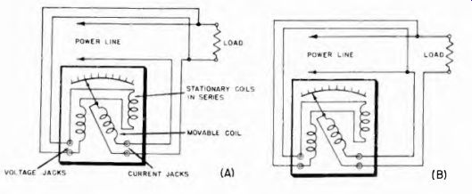
Fig. 5-4. Organization of dynamometer type wattmeter.
5-3. The Electrodynamometer Wattmeter
In Section 2 the electrodynamometer ammeter and voltmeter were discussed, and their basic principle of operation explained. This same meter becomes a wattmeter if the coils are connected a little differently.
The dynamometer wattmeter consists of two coils, one stationary and one moving, just as in the dynamometer ammeter. The stationary coil has many turns of small wire with high resistance. The movable coil has a few turns of large wire with low resistance. It is pivoted and has jeweled bearings, springs for control, and air damping such as the dynamometer ammeter and voltmeter have.
The high-resistance coils are connected across the voltage source, or across the device whose power consumption is to be measured. The movable coil is connected in series with the device. These connections are shown in Fig. 5-4 (A). Current through the load also passes through the movable coil. Current through the voltage coil is proportional to die voltage across the load. The interaction of the magnetic fields from the fixed and movable coils causes the movable coil to rotate. The torque on the movable coil is proportional to the current and also to the voltage, and is therefore proportional to their product. The meter pointer thus registers according to the power consumption, or E x I.
The torque is greatest when the voltage and current peaks occur at the same time (in phase) and becomes relatively less as the current and voltage peaks are gradually separated, in time up to 90 degrees.
Thus the instrument also takes into account the phase and power factor.
The movable current coil has low resistance and inductance so as not to disturb the circuit into which it is connected. The inductance of the fixed voltage coil also is low relative to its resistance so the current through the coil is in phase with the voltage. Sometimes a non-inductive resistor is connected in series with the voltage coil to reduce the relative reactance to resistance in the circuit and to keep the current as closely as possible in phase with the voltage.
Since both the current and voltage coils have resistance, the watt-meter itself consumes some power. This loss is usually specified on the instrument, and represents the loss at full scale deflection. A typical wattmeter has a power loss of 2 watts in the voltage coil and 1 watt in the current coil. Since the percentage error of readings due to meter power-consumption tends to be greater for lower readings, the accuracy is best if the upper part of the scale is used.
There are two possible ways of connecting the wattmeter, these are shown at (A) and (B) of Fig. 5-4 At (A), the current through the potential (voltage) coil also goes through the current coil. Therefore the current coil is measuring both the load current and the potential coil current. At (B) the potential coil is measuring the voltage of the load added to the voltage across the current coil. In each case some error is inevitably introduced, because the voltage and current are not exactly those of the load.
Some wattmeters are compensated so that the power loss due to wattmeter connections is corrected for in the instrument. Otherwise, for exact measurements, the power consumed by the wattmeter should be subtracted from the final wattmeter indication. The meter power loss can be easily checked by disconnecting the load. The potential coil is then in series with the current coil. The uncompensated meter reads its own power loss. If the wattmeter is compensated the reading is zero, if there is a numerical reading the number is the correction factor which should be subtracted from the reading when the load is connected.
Both the voltage and current coils have definite ratings and overload of either can damage the meter. For example, a typical wattmeter is designed to measure a maximum of 200 watts; the current coil has a maximum rating of 3 amperes, and the potential coil has a maximum rating of 130 volts. If either of these ratings are exceeded overload may occur.
In dynamometer wattmeters deflection is linear and practically uniform over the full range of the wattmeter; doubling the power produces twice the deflection. Because the voltage and current coils are separately connected, power is doubled when current through either the voltage or current coil doubles. When the currents through both coils double there is four times the power, and thus four times the deflection.
Dynamometer wattmeters automatically take into account the power factor of the circuit. The wattmeter always reads true power.
5-4. Usefulness of the Wattmeter in Servicing Equipment
The wattmeter is useful not only in determining how much power a device is taking under normal conditions, but is also useful as a detector of defective conditions. If some component of a unit is causing leakage or undue loading, the unit draws more power from the line than it normally would. This is particularly true of such units as radio and tv receivers, amplifiers, intercommunication systems, radio transmitters and the like, which are a-c or d-c power-line operated. For example, if a device is rated at 50 watts for normal operation and is consuming 100 watts, there is a definite indication of a defect causing overload somewhere in the circuit. The technician would then look for such things as shorted or leaky filter or bypass capacitors, gassy tubes, short-circuit between tube elements, failure of bias on one or more tubes, etc. These would cause excessive currents to flow and thus dissipate extra power, all of which is supplied by the line, and thus shows on the wattmeter.