Some meter movements will read alternating voltage and current as they are and thus do not have to be "adapted." These are the moving-iron or vane and dynamometer types described in Section 2.
The scales are calibrated in rms values, and sine waveform voltage or current is assumed. However, as has been mentioned, these movements have such low sensitivity that they are of limited use in electronic circuits. Most of the a-c measurements in electronic and electrical circuits in general are now made with a d-c moving-coil permanent-magnet movement, operating in conjunction with some kind of rectifier arrangement which converts ac to de for application to the meter. It is this adaptation of the d-c permanent-magnet meter with which we are primarily concerned in this section. The reason being that rectifier type instruments afford a-c meters of relatively high ohms-per-volt --- from 1,000 to 5,000 ohms-per-volt.
6-1. Adding a Rectifier to a D-C Meter
Modem instrument rectifiers for power frequencies and audio frequencies are mainly of the copper-oxide. type. These are constructed of a series of copper discs clamped flat together in a stack. On one side of each disc is a coating of copper oxide forming a layer of copper oxide between each adjacent pair of discs. Washers made of lead are clamped against each oxide surface to improve the contact, and the whole assembly is held tightly together by an insulated bolt running through the center. Typical examples of instrument rectifiers are shown in Fig. 6-1.
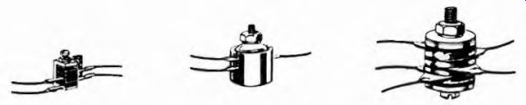
Fig. 6-1. Typical copper oxide instrument rectifiers.
The rectifier used with an a-c meter may be a single unit or a group of individual rectifiers connected together. The simplest arrangement is the single-unit half-wave rectifier of Fig. 6-2. The rectifier stops current flow during the negative alternations, leaving the current waveform as shown at the right. One cycle of the meter-current waveform is analyzed in the lower part of the illustration, showing how the average value in the half-wave rectifier system is equivalent to 0.45 times the rms value of the alternating current which would result without the rectifier. This means the rms value is 2.22 times the average value indicated on the d-c scale of the meter. Thus the d-c scale of the meter can be changed to read rms ac by multiplying each value by 2.22.
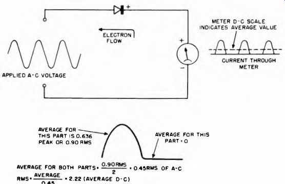
Fig. 6-2. The simplest meter-rectifier circuit. The meter responds according
to the average value of the rectified current. In the lower part of the illustration
this average is shown to be 0.45 times the rms value of the measured a-c.
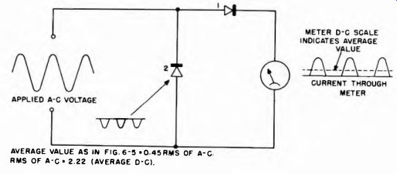
Fig. 6-3. Double-rectifier arrangement, which minimizes "back-current."
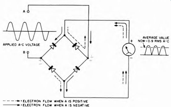
Fig. 6-4. Four section rectifier connected in bridge circuit giving full-wave
rectification.
The copper-oxide rectifier is not a perfect rectifier, but allows a very small back-current to flow. Thus a slight error is introduced in the arrangement of Fig. 6-2. To minimize back-current, the arrangement of Fig. 6-3 is often employed. Here a second rectifier is connected across the source of measured voltage so that it draws current when the first rectifier is non-conducting. This shunts the meter and first rectifier during such periods, minimizing the reverse current. The waveform of current through the meter is the same as for Fig. 6-2, and the same relations hold.
The most sensitive arrangement is that using the bridge rectifier illustrated in Fig. 6-4. Four rectifier units are connected to each other, to the meter, and to the source in the manner shown. When the source of measured voltage has one polarity one set of rectifiers conducts, and when the source has the opposite polarity the other pair conducts.
The arrows show the direction of electron flow for each polarity of the source. The result is that current flows in the meter in the same direction for both half-cycles of the a-c wave. For this reason, the average value of the pulsating current through the meter is 0.9 of the a-c rms value. This is twice the relative value of the average in the half-wave rectifier circuits of Figs. 6-2 and 6-3. Thus the meter response is twice as great for a given current, and the sensitivity is that much better.
Rectifier units are available in very compact form to take care of all of these types of circuits. The ones with several rectifier units are built with these units stacked together in one physical assembly as shown in Fig. 6-1. Instrument rectifiers have ratings ranging from 1 to 5-v rms and from 1 to 75-ma dc.
Copper-oxide rectifiers are subject to certain limitations which affect their application and the accuracy of the readings. The characteristics of the rectifier change with temperature and condition of overload. The resistance of the rectifier also changes with a change of current through the rectifier. This latter effect is of major importance at low rectifier current densities, (when low values of current are flowing through the meter). In this connection the "forward" resistance increases at low values of current. Therefore the scale of the rectifier-type meter designed for the measurement of low a-c quantities is crowded near the low end. Further, because of this condition, calibration for alternating current does not hold for the measurement of direct current. At high values the rectifier type meter is comparatively linear and provides a substantially uniform scale.
6-2. Problems in Adding Multipliers to the Rectifier Meter
In order to provide practical a-c voltage scales, multiplier resistors must be used in series with the meter movement and the rectifier. As soon as this is done the efficiency of the copper-oxide rectifier is reduced considerably, unless measures are taken to counteract the effect.
This problem is largely overcome by use of the circuit of Fig. 6-3, shown again with a multiplier resistor R in Fig. 6-5. On one alternation current goes through the meter movement and rectifier 1, with the usual process of half-wave rectification taking place; on the other half-cycle current is bypassed around the meter movement and rectifier 1, and is shunted through rectifier 2. The meter and rectifier 1, with 50,050 ohms, are practically an open circuit compared with the 1,000- ohm forward resistance of rectifier 2, and thus draw practically no reverse current.
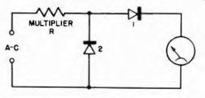
Fig. 6-5. Use of multiplier resistance in rectifier type a-c voltmeter.
6-3. Scale-Linearizing Shunt
It has previously been mentioned that the forward resistance of the copper-oxide rectifier increases when relatively low currents are being rectified. Forward resistance can vary from 2,000 to 500 ohms as current in the rectifier varies from 0.1 ma to 1 ma. This tends to make the calibration non-linear, with considerable crowding toward the low end of the scale.
This difficulty is partially relieved by shunting the meter, and not the rectifier, with a resistor (as shown in Fig. 6-6). This causes the rectifier 1 to carry more current than the meter; thus, when the meter is reading low values, the rectifier is carrying a high enough current to keep it in the relatively linear portion of its characteristic.
Of course the shunt lowers the sensitivity on voltmeter scales, because it takes more current to produce a given deflection. Typically, before the shunt is connected, the sensitivity of the meter in Fig. 6-6 alone is 1/.0002 = 5,000 ohms per volt; after the shunt is connected it takes 1 ma to deflect full scale, thus the sensitivity drops to 1/.001 - 1,000 ohms per volt. However, the improved scale calibration is generally considered worth the price of the lost sensitivity, and many commercial instruments use the shunt.
6-4. Sensitivity of Rectifier-Type Instruments
The shunt resistor described previously is placed in the circuit only when a-c quantities are being measured. This is one reason that rectifier-meter sensitivities are ordinarily considerably lower than d-c meter sensitivities in the same combined instrument. Also, the rectifier has a definite amount of forward resistance and impedance which, for simplicity, we have ignored in previous discussions. However these are present, and result in less current through the meter than would be the case in perfectly resistanceless rectification.
Because of these two factors, meter-rectifier sensitivities are ordinarily much lower than d-c meter sensitivities in combination instruments using the same meter movement. For the better instruments commonly available, a d-c sensitivity of 20,00 ohms per volt is common.
For a-c voltage measurements, most instruments feature a sensitivity of 1,000 ohms per volt, with a few having as high as 5,000 or 10,000 ohms per volt.
6-5. Frequency Characteristics of Copper-Oxide Meter Rectifiers
Because the copper-oxide rectifier has internal capacitance, bypassing of higher frequencies takes place and the rectified current passing through the meter is accordingly decreased at the higher frequencies.
This occurs to a much lesser degree today than in the designs of years ago because meter rectifiers have undergone substantial improvement in design. Presently, the usual frequency error is about 1 percent up to about 20,000 hz, and a copper-oxide rectifier type of a-c voltmeter is down approximately 3 db at around 70,000 hz.
Except for the necessity for correction because of the frequency characteristic of the rectifier, the meters used especially for a-f measurements are the same as those already described. An a-f voltmeter is simply an a-c meter, of the rectifier type, used at higher frequencies.
However, the scale of the audio-frequency meter is usually calibrated ...
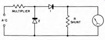
Fig.
6-6. Circuit with scale linearizing shunt resistor.
... in different units, either decibels (db) or volume units (VU) . Because of this, such meters are often referred to as "db" or "VU" meters.
6-6. The Decibel and the DB Meter
The decibel or db is a unit of power ratio, although it is just as often used in connection with ratios of voltage and current. It was developed to provide a convenient expression for power or voltage ratios of large magnitude, such as are used in audio work and with audio equipment.
The db meter, on the other hand, is a direct reading instrument which is calibrated in db values above and below a reference standard, thereby enabling direct measurement of a power or voltage level relative to the standard.
6-7. The Decibel Reference Level
The decibel is defined by the following equations:
Number of db - 10 Log db = 20 Log
° El db = 20 Log 12 where P2 is output power E1 is input voltage P1 is input power 12 is output current E2 is output voltage I1 is input current
Suppose, in the expression for db in terms of power levels, we substitute a definite standard specified power level for P1, to which we compare any other power level P2. Then, instead of expressing a power level in watts or milliwatts, we could say it is equal to so many db, all the while knowing that we mean this many db above (or below) the specified standard reference level.
In order that the standard reference level be expressed in terms of voltage as well as power, the resistance of the standard load must also be specified.
Two different reference levels are commonly used. Unfortunately, neither one has been universally accepted in preference to the other, so the standard used must be specified for each meter. The two standards are shown in Fig. 6-7: the tendency is now toward more general use of the 1-mw standard shown in (B) The units dbm and Volume Units (VU) are the same as db except that the reference level is 1 mw into 600 ohms instead of 6 mw into 500 ohms.
A db, dbm, or VU meter is simply a rectifier type a-c meter with the scale changed from voltage to "level" units. It will be noted that in multimeters in which there are both a-c voltage and db scales, the "0-db" point will correspond to either 1.732v a-c (standard A in Fig. 6-7) or 0.775v a-c (standard B). See Fig. 6-8 (A) for the db scale. The figures for db (or dbm or VU) above this zero point are marked with plus signs; the figures below this point are marked with minus signs.
Minus quantities on the db scale do not mean any change in polarity of electrical quantities. When the db reading becomes negative, it means that the ratio of the measured voltage to the reference voltage is less than 1. Thus, in a load of 600 ohms, a voltage of 0.775v rms equals 0 dbm or VU; voltages higher than 0.775v rms have plus values and those lower than 0.775v rms have minus values.
In ordinary multimeters and db meters the rectifier-type a-c meter is used, without any special refinements. For applications in which broadcast program material and other rigidly-controlled audio signals are to be measured, a special meter called the "VU Meter" is used. The reference level, reference deflection on the scale, damping, frequency response, types of scale and other factors are carefully specified. The standard, recommended VU meter scales are shown in Fig. 6-8B. Besides the VU scale, another scale, proportional to (but not equal to) voltage is also included, with an arbitrary value of 100 at the 0 VU point.
VU meters use full-wave rectifiers, usually of the bridge type, because of the following requirement: The indication must be independent of the poling of the indicator when measuring unsymmetrical waves. Such characteristics can be obtained by the use of a direct current instrument in conjunction with a full-wave rectifier.
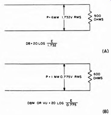
Fig. 6-7. Reference standards for db and VU meters.
In most applications, VU and other level meters are used for relative readings, and the zero level may be any voltage desirable or convenient at the moment. If an absolute reading is required, however, it must be taken across an impedance of 500 or 600 ohms, whichever the scale calls for.
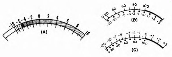
Fig. 6-8. Db scale and standard VU meter scales. The scale at (B) emphasizes
arbitrary units proportional to voltage. The scale at (C) emphasizes the VU
calibration.
6-8. Output Meters
An output meter is a db or VU meter equipped with a load resistor across which level readings may be taken. The scale of an output meter is usually calibrated in both db (or VU) and power (watts, milliwatts, microwatts). The load resistor in the meter assembly is used as a test load for the output circuit of a radio receiver or audio amplifier. The power output of the device can then be read directly from the meter scale.
6-9. Effect of Waveform on Rectifier Meter Readings
When a d-c meter is used with a rectifier, it responds to the average value of the a-c half-cycles. However, the scale is calibrated in rms values.
With a sine wave the rms value is 1.11 times the average value (average value times form factor). Therefore the rms calibrations are always 1.11 times the average value which would be indicated at any point.
However, as soon as we try to read a-c voltage of a waveform other than the sine, we run into an error. This is because the form factor for waveforms other than the sine is not 1.11. For example, Fig. 6-9 shows the familiar "sawtooth" waveform used in the deflection circuits of tv receivers, and its average and rms values. Since the form factor is 1.15 instead of 1.11, the regular rectifier a-c meter reads about 4 percent low. Although the average value operates the meter, its scale is calibrated to indicate 1.11 times the average. Thus the indicated rms value is lower than the actual rms voltage, which is 1.15 times the average value. Of course, if we know what the waveform is, we can correct each reading by multiplying it by 1.15/1.11, or 1.036.
6-10. Current and Potential Transformers
Although we are primarily concerned with problems involving the rectifier type of meter, the basic a-c types, such as the moving-iron and dynamometer, are also encountered. A word about the extension of their scales should be said. Shunts are not as frequently used with these meters, instead current scales are extended by means of current transformers.
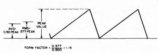
Fig. 6-9. Sawtooth waveform and relative value of the rms and average compared
to peak. The form factor here is 1.15, compared with 1.11 for the sine wave.
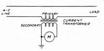
Fig. 6-10. Use of the current transformer. This is the method used to extend
the scales of current meters such as the moving-iron and dynamometer types.
The secondary winding of the current transformer is connected to the meter, and the primary of the transformer is connected into the circuit where the current is to be measured (as shown in Fig. 6-10). Due to the design of the current transformer, the load current is stepped down by a predetermined factor so that the secondary current is within the operating range of the current meter. The step-down ratio between the primary and secondary windings then becomes a multiplying ratio applied to the current indication of the meter. For example, in Fig. 6-10, the connections to the transformer are such that a step-down ratio of 10 is being used, full-scale deflection of 1 ampere in the secondary circuit is the equivalent of 1 x 10 or 10 amperes flowing in the primary or load circuit.
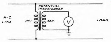
Fig. 6-11. The scales of moving iron and dynamometer voltmeters can be extended
by the use of a potential transformer, connected as shown above. Voltages far
in excess of the volt-meter range can be read due to the step-down properties
of the transformer.
A-C L/NE LOAD
Such transformers are designed to cover a wide range of step-down ratios, from as low as 2 times to as high as several thousand times. Usually the transformers are designed to operate with a meter rated at from .5 to 1 ampere full scale, although some small current transformers are designed for operation with 2-ampere meters. These transformers are suitable for use with all types of a-c current meters.
The second method makes use of the potential transformer. The wiring connections to a voltmeter are shown in Fig. 6-11. The transformer is designed to provide a predetermined step down ratio when used in connection with certain specific meters. These meter specifications state the full-scale range of the meter and its current consumption.
In other words, the secondary of the potential transformer must work into a certain definite load. The step-down ratios which cover a wide variety then become the multiplying factors which are applied to the voltage indication upon the voltmeter. Thus, if the step-down ratio is 100 to 1 and the voltmeter indicates 10 volts, the voltage present across the primary of the transformer is 10 x 100 or 1,000 volts. Such transformers are usable over a frequency range of from 25 to about 133 cycles.
One precautionary measure which must be remembered when potential transformers are used is that one side of the secondary should always be grounded, as shown in Fig. 6-11.