Section 6 explained that rectifier type a-c meters are satisfactory for use with frequencies up to about 70,000 hz. Of course, with correction, they can be used much higher. However, they are not suitable for measurement of r-f currents at several megacycles and higher. At these frequencies, special measures are taken to adapt simple meter movements, primarily the permanent-magnet moving-coil type, to current, voltage, and power measurements There are two ways of doing this: (1) by use of a thermocouple with a meter movement, and (2) by use of a high- frequency tube or crystal rectifier probe and a meter movement. These methods are considered in this section.
7-1. The Thermocouple Ammeter
In radio transmitters, thermocouple ammeters are generally used for measuring r-f current. These meters may be connected in the antenna circuit so as to measure antenna current and power, in a "dummy load" used for testing, or in other parts of the transmitter circuit where r-f current is to be measured. They are also used in induction heating and diathermy units.
A thermocouple consists of two wires, or other pieces, each of a different metal, joined at one end. If the junction of these metals is heated, a d-c voltage appears across the free terminals. This phenomenon is called thermoelectricity.
In thermocouple ammeters, use is made of this property of a thermocouple to indicate the temperature of a wire. Since the wire whose temperature is indicated is carrying the current to be measured, the thermocouple voltage is also proportional to the current in the wire.
This is because the current in the wire has a heating effect (I2R) which raises the wire's temperature according to the amount of current in it. The temperature of this wire applies heat to the thermocouple, which develops a voltage. This voltage is applied to a sensitive meter of the permanent-magnet moving-coil type. Thus the reading of this meter is proportional to the current in the wire. The principle of the thermocouple ammeter is illustrated in Fig. 7-1.
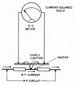
Fig. 7-1. Basic principle of the thermocouple meter. R-f current through the
heater generates heat which raises the temperature of the thermocouple junction.
The increased temperature of the couple causes it to produce a voltage, deflecting
the pointer of the d-c instrument accordingly.
7-2. Thermo-Ammeter Frequency Response and Heater Design
Two factors influence the type of heater used; these factors are frequency and current value. High values of either or both make special physical design of the heater necessary. This is because r-f currents do not distribute themselves uniformly through the cross-section of the conductor. They flow mostly in a thin layer, or "skin" at the outer surface; this effect is known as "skin effect." The higher the frequency, the thinner the skin in which most of the current flows. Since the current flows through less metal at higher frequencies, the effective resistance is higher. The heat generated to operate the thermocouple is determined by I^2R; thus as the effective R increases with frequency, the heat generated for a given current increases. In this manner the thermocouple voltage is increased and the meter reads high at higher frequencies. This effect extends in greater degree to lower frequencies when the current is high, because the heat is proportional to the current squared.
For relatively low frequencies, and currents up to about 2 or 3 amp, a solid wire heater is usually used. Above these values, a tubular heater is substituted for the solid one. The thinner the walls of the tube, the less the frequency error. Of course there is a limit to how thin such a tube can be made; this limit is about 1 mil (one thousandth of an inch). The tube is made of a platinum alloy of resistance about 17 times that of copper. With such a heater, frequency error can be kept to about 5 percent up to about 100 me, and about 10 percent up to 150 mhz. 150 me is about the top limit for which this type of meter should be used for making absolute readings, that is, readings that are to be used in calculating power, etc. However the thermocouple ammeter responds well and can be used as a qualitative indicator, or for comparative readings to see which of two currents is greater, at much higher frequencies.
7-3. Scale Calibration of Thermocouple Ammeters
In these meters, deflection is proportional to the amount of heat generated in the heater wire. This, in turn, is proportional to the square of the current passing through it. Therefore, the thermocouple meter has a square-law scale. Since the calibration divisions in the lower, or extreme left, portion of a square-law scale are crowded, readings in that area are less accurate than those taken elsewhere on the scale.
Thus thermal meters usually are selected so that the expected value of measured current will place the pointer at least half-way up the full-scale range. For example, if the estimated current to be indicated is 7 amperes, the meter range should not exceed 10 amperes.
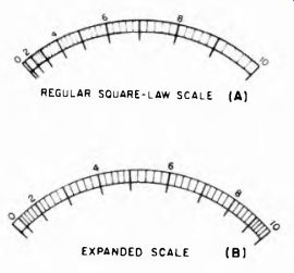
Fig. 7-2. How the scale of a thermocouple meter can be "expanded" to
be more uniform over the whole range by use of a d-c instrument with specially
shaped magnet and pole-piece. REGULAR SOUARE-LAW SCALE (A) EXPANDED SCALE (B)
The crowding in the lower portion of the scale can be somewhat relieved by the use of a special d-c meter movement. In this movement, the magnetic gap between the permanent magnet and the pole piece is shaped to be greater as the moving coil and pointer swing to higher current values. This makes the instrument progressively less sensitive as current increases, and compensates for some of the low-scale crowding.
This is often referred to as "expanding the scale." Figure 7-2 shows how a regular square-law scale can be improved by this process.
7-4. Vacuum Thermocouples
In ordinary thermocouples an appreciable amount of heat is lost to the air surrounding the couple by convection currents (air motion carrying heat). Accordingly, to improve sensitivity, vacuum thermo couples are being manufactured. These are mounted inside a glass envelope, resembling that of a small vacuum tube, with both the couple and the heater contained, and leads from each brought out through the envelope. These units are made small enough to be incorporated into the case of some meters or can be connected externally. See Fig. 7-3.
7-5. Shunts and Multipliers for Thermocouple Meters
The range of a thermocouple meter can be increased in the same manner as range increases are made in other types of meters, i.e. by shunting or by series resistance. Shunts and multipliers are used in conjunction with the heater in such a way that its rating is never exceeded.
It must be remembered, however, that a shunt or multiplier is quite critical, especially if the meter is to be used at relatively high radio frequencies. The least inductance or excess capacitive effect can intro duce serious error. Shunts are usually straight, solid wires or bars connected directly across the meter terminals.
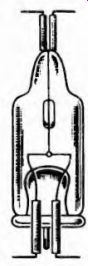
Fig. 7-3. An example of vacuum thermocouple used with r-f meters; Courtesy
Field Electrical Instrument Co.
Thermocouple voltmeters may use several thermocouples in series to provide the required voltage rating. Sensitivities of up to 500 ohms per volt are obtainable.
7-6. Use of Thermocouple Meters on Direct Current
The heating effect in a wire or other conductor is the same for a given resistance and current, whether the current is ac or dc. Thus, although thermocouple meters are most useful for radio-frequency currents, at which there are no other types as suitable, they can still be used on audio-frequency currents and direct current.
However, when a thermocouple meter is used to measure direct current or d-c voltage, a "poling" error may result due to a slight d-c voltage drop being applied to the part of the heater which the thermocouple contacts. For this reason, the d-c values should be read with the connections one way, then with the meter connections reversed, and the results averaged. This will cancel out the "poling error."
7-7. The Hot-Wire Ammeter
The hot-wire ammeter was described in Section 2. This instrument makes use of the warping or sagging of a piece of wire, when it is heated by the electric current it is carrying, to indicate the value of the current.
Since it is the heating effect which produces the action, and this applies equally for ac and dc, the meter can be used for either. At one time these meters were widely used as r-f ammeters.
7-8. Use of Diodes for R-F Measurement
Another method for adapting simple meters for r f measurement is with the use of a diode rectifier, which efficiently rectifies the r-f current or voltage to dc. This de is then measured with a sensitive moving-coil meter or a vacuum tube voltmeter. Germanium, silicon, and other crystal diodes have low capacitance and are excellent for high radio frequency rectification. Because these rectifiers are most frequently used with vacuum tube voltmeters, they are discussed in Section 9.