When Dad first brings home a tape recorder to record the children' s voices or practice his speech for the Company's forthcoming Founder's Day banquet, the entire family gathers around. Following the first flush of excitement and after everyone has recorded his voice, Dad is asked the inevitable question, "How does it work?" Typically, Dad might reply, "Why, with push buttons, of course." Yet an increasing number of tape recorder owners have not been content to be mere "button pushers," and as a result have started the still-growing cult of amateur sound hunters and golden ear addicts that have turned high fidelity into a challenging but highly rewarding hobby.
As the tape recorder owner's enthusiasm increases, his ear slowly changes from the tin to golden variety. He will drive miles to compare his tapes with those of fellow amateurs or with the results of local professionals. And, as a result, he will invariably seek to improve his technique.
And just as the camera fan soon realizes that he can improve his pictures by learning what happens when he clicks the shutter, the tape enthusiast learns how to get the most out of his recorder when he understands how it works.
There has been an abundance of papers presented before technical society symposiums on the theory and principles of magnetic recording.
The technical journals repeatedly carry highly detailed scientific material and some books have already been written on the subject of magnetic recording. Nevertheless, physicists and engineers are still not in complete agreement on some of the finer points. Symposiums have broken up in disagreement. Controversy is still prevalent among magnetic -recording theoreticians, a healthy sign of industry growth and progress.
To thoroughly understand the technical phase of magnetic recording requires a considerable amount of prior knowledge and experience in electricity and magnetism. However, the basic principles are not too difficult to understand. To thoroughly grasp the fundamentals of magnetic recording is basic to getting the most in performance out of any tape recorder, from the simplest home machine to the finest studio recorder.
Sound Waves - Electrical Waves
Sound, by its very nature, is an auditory sensation experienced through the ear. Sound is caused by an alteration in pressure, particle displacement or particle velocity produced when the air is set into ...
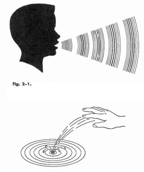
Fig. 2-1. Sound is Caused By Alteration in Pressure, Particle Displacement,
or Particle Velocity Produced When the Air is Set in Motion.
Fig. 2-2. The Action of Sound Waves Radiating From a Single Source Can Be Compared to Dropping a Stone Into a Still Pond.
... motion. (See Fig. 2-1.) The action of sound waves radiating from a single source can be compared to dropping a stone into a still pond. The waves of water move outward in all directions, continuously expanding as shown in Fig. 2-2.
Sound may be produced by a vibrating body such as the diaphragm of a loudspeaker or a violin string or, for example, an intermittent air stream such as a human voice or lip-reed instruments. Sound travels through the air in surges of energy, consisting of a condensation or a high-pressure pulse of air followed by a rarefaction or a low-pressure pulse. Anyone who has stood at the seashore, fascinated with the ocean waves crashing against the beach, will note another similarity to sound waves. The ocean wave surges forward, draws back, and its crest plunges forward once again.
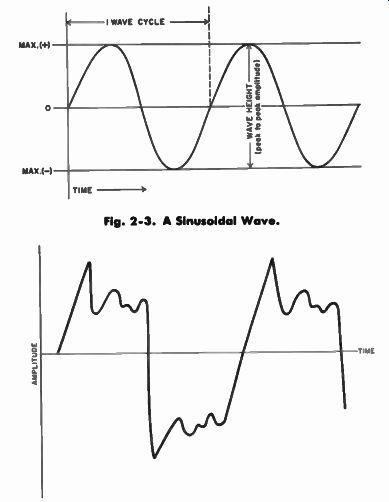
Fig. 2-3. A Sinusoidal Wave. Fig. 2-4. A Complex Waveform.
The human ear receives the sound waves and converts them into electrical impulses which are "translated" by the nervous system of our body.
Sound waves, like electrical waves or impulses, can be graphed.
Variations of pressure - concentration and rarefaction of the air particles - when plotted, form a wave. If the sound consists of only one frequency and is of constant strength, the wave will be sinusoidal in shape. Sound waves of a human voice or a musical instrument are composed of many frequencies, each with its own particular strength, all existing at one time.
Fig. 2 -3 shows the amplitude of a sinusoidal wave and the number of time it repeats itself in a second. The height of the diagramed sound wave indicates the intensity or loudness of a sound, while the number of complete wave cycles per second gives the pitch of sound.
The more wave cycles per second, the higher the pitch. Fig. 2-4 shows a complex waveform indicating a number of frequencies of different amplitudes existing at one time.
Again, this phenomena can be compared to dropping a stone into still water. The smaller the stone, the weaker and smaller the ripples.
When a large stone is dropped into the water, the waves will be large, strong in force, and will radiate further.
The Decibel - Db.
Resembling a variable amplifier, the human ear is ingeniously designed. It is sensitive to the weak sound of a scampering mouse while limiting the volcanic roar of a jet engine to a tolerable limit.
Nature enables us to hear sound intensity logarithmically for our survival and protection. The louder the sound, the less sensitive our ear is to it. The variation in sound intensity between the dropping of a pin and the explosion of a bomb is many millions of times. If we were to suddenly hear linearly, or in exact proportion to the intensity of sound, it is doubtful if we could survive hearing the blast. Fig. 2-5, shows the difference between a linear and logarithmic function.
LOGARITHMIC FUNCTION
SOUND LOUDNESS
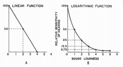
Fig. 2-5. Graphs Showing the Difference Between a Linear Function (A)
and a Logarithmic Function (B). Electrical energy can be expressed and
measured in several ways, such as in volts or watts. The volt is a unit
of electrical potential and the watt is a measure of power. However, since
in recording, sound is received by a microphone and converted into an
electrical wave, the intensity of this wave is expressed in decibels.
This is proportionate to the log of a voltage or power ratio, representing the acoustic properties of our hearing.
The bel is named after Alexander Graham Bell, pictured in Fig. 2-6, who discovered that humans hear sound intensity logarithmically.
The audible range of sound is so large it is more convenient to use a smaller measure scale, decibels. The decibel is one-tenth of a bel and is an expression of the ratio of one power to another power.
If we double the electric power in a system, we increase the sound level 3 db, or a perceptible amount. A really trained ear can hear a 1 db difference in level while most people can just distinguish a 2 db change in the sound level of voices or music. Therefore, when we double the loudness of a sound, it is in effect only 3 db higher.
When a sound is four times as loud, it is 6 db higher. If a sound were eight times louder, the difference would be 9 db.
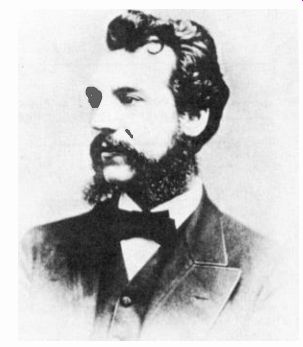
Fig. 2-6. The "Bel" is Named After Alexander Graham Bell, Who is
Pictured Here.
If an electric circuit such as an amplifier is terminated in a reasonably constant load such as a loudspeaker, decibels can also be expressed in terms of voltage. The relationship becomes such that if one doubles the voltage, there is an increase of 6 db.
Frequency -- The number of waves per second - the frequency of the wave - is measured in terms of cycles per second (cps) in the case of both sound and electricity. A low-pitched tone causes the air to vibrate slowly, perhaps only 30 times a second, the lowest frequency audible.
The highest frequency is generally between 14,000 and 18,000 cps for young and middle-aged people. Older people often cannot hear above 5 or 6,000 cps.
When the vibrating air waves reach the sensitive diaphragm in a microphone, they cause it to generate an alternating electrical current of the same frequency. As the diaphragm moves in, it creates a positive current, and as it moves out, it creates a negative current or vice versa.
Intensity -- The intensity of the vibrations of the sound wave are also faith fully reproduced in terms of voltage, generally expressed in db.
The microphone translates a loud sound into a large voltage, while a softer sound results in a weaker signal.
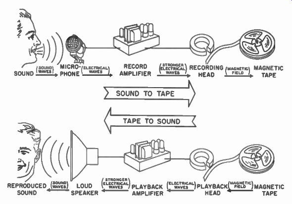
Fig. 2-7. From Sand Waves to Tape and From Tape to Sound Waves.
The electrical waves of alternating voltage go from the microphone through several stages of voltage amplification, through a low power stage; and then transformed into current, they enter the recording head which is actually an electromagnet. This process is clearly shown in Fig. 2-7.
Electromagnets-- Magnetic recording is an extremely complex process, involving a study of advanced physics. The labyrinthics of magnetic theory are deep and dark, and even experienced academicians sometimes lose their way. The following explanation is intended to give a general idea of the magnetic recording process rather than a specific, highly technical explanation of how it works. No mention is made of either a direct current or an alternating-current bias, since the theories involved are lengthy and require considerable use of higher mathematics and special treatment of the characteristics of magnetic materials.
An electromagnet is made by wrapping an iron core with wire to form a coil. When current flows through the wire, the core becomes a magnet. One end, or pole, of the iron core is a north pole. The other end is a south pole. If the direction of the current flow changes, the polarity of the electromagnet is reversed.
A strong current produces a strong magnetic field, while a weaker current results in a correspondingly weaker field. Similarly, an alternating-current cycle causes each pole of the electromagnet to change through one complete cycle in polarity from north to south and back to north.
Around any magnet is an area of magnetic attraction commonly known as a "field," which is illustrated in Fig. 2-8 in terms of lines of magnetic force. The more closely spaced are the lines, the stronger the magnetic attraction.
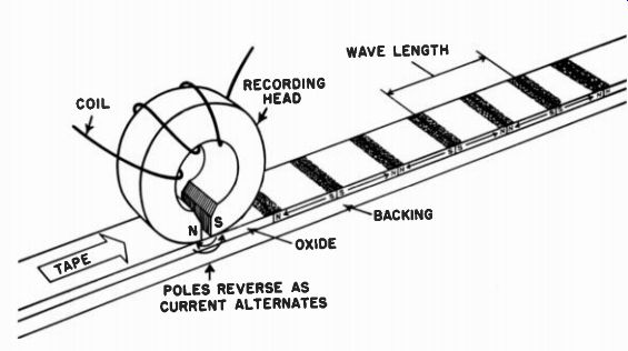
Fig. 2-8. Around Any Magnet is a "Field". A Strong Current
Produces a Strong Field and a Weaker Current Produces a Correspondingly
Weaker Field.
These lines of magnetic force also have direction. Physicists have arbitrarily defined force lines as going from north to south outside the magnet, then completing their circuit by going from south to north inside the magnet.
The Magnetic Recording Head -- In the case of the recording head as shown in Fig. 2-9, the core is cut in a rectilinear shape with the poles almost touching, as little as .00025", or 1/4-mil apart. This distance is referred to as the "gap" of the head.
The cores of the recording head are magnetically "soft." That is, the head becomes magnetized easily and instantly when current flows into the coil, but loses its magnetism just as rapidly when the current stops. The recording head is unlike a permanent magnet, or even the oxide on the tape itself, which is made from a magnetically "hard" material. The iron oxide coating on the tape, being magnetically "hard," will hold its magnetism for an indefinite period of time.
Whenever a surge of positive current from the microphone goes through the coil, it magnetizes the recording head in one direction.
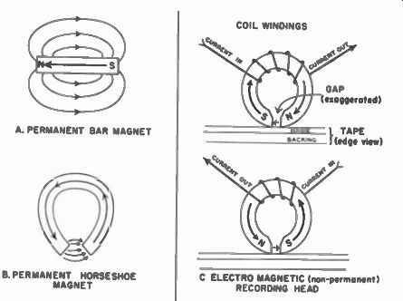
Fig. 2-9. Similarity Between a Permanent Magnet Structure and a Magnetic
Recording Head. A. PERMANENT BAR MAGNET B. PERMANENT HORSESHOE MAGNET
C ELECTRO MAGNETIC (non-permanent)
RECORDING HEAD
When the current alternates and sends a surge of negative current into the coil, the head is magnetized in the opposite direction, or the poles alternate between north and south.
Tape Magnetization -- When the iron -oxide coated tape is in contact with the recording head, it offers an easier path for the magnetic lines of force to follow than does the air gap. Therefore, following the course of least resistance, most of the magnetism gets across the gap by flowing through the iron-oxide coated tape.
While the magnetically "soft" iron ring of the electromagnet loses its magnetism when the current stops, the magnetically "hard" coating on the tape retains its magnetism and the magnetized area becomes a small bar magnet itself. Because the lines of force left inside the tape point in one direction, that direction must necessarily be north. The other end, therefore, becomes south. This is shown at A, in Fig. 2-10.
At B, the current entering the coil is zero at its point of alternation and, consequently, does not create a magnetic field at that time. As a result, the tape moves a fraction of an inch without being magnetized any further.
However at C, when a surge of negative current comes into the coil, a magnetic field in the opposite direction is set up, causing the polarity of the electromagnet to reverse itself.
Again, the lines of magnetic force at the poles find it easier to flow through the iron-oxide coated tape than across the air gap. Thus the tape is permanently magnetized, but this time, in the opposite direction.
At D, the tape has again moved, but since the current is not flowing, no new lines of force are set up at that point.
As a result, the surges of alternating current leave the tape permanently magnetized by setting up a series of lines of force of opposite polarity, creating a series of bar magnets on the tape.
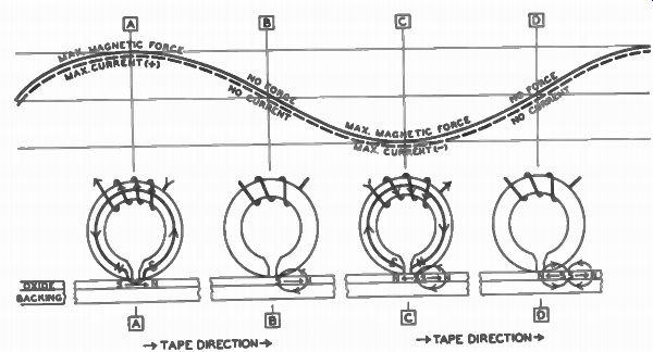
Fig. 2-10. Shown Here is the Magnetization or Recording Process. Effects
of Bias and Hysteresis are Not Shown to Simplify the Drawing.
Because the tape is moving, these poles occur at recurring intervals along the tape, in a definite pattern. The frequency of the signal and the speed at which the tape moves, determines the distance between poles, while the strength of the current, or voltage, determines the magnetic strength of each pole.
As shown in Fig. 2-10, the magnetic pattern on the tape, for a 30 cps tone, consists of 30 magnetic fields pointing toward south, alternating with 30 magnetic fields pointing toward north.
In effect, the oxide coating of the tape is broken up into 60 individual bar magnets, laid end to end, every second the tape moves across the gap. On a tape recorder operating at 7 1/2 ips, the 60 bar - magnet patterns would cover a space of 7 1/2 inches on the tape. A 10,000 cps note would be represented on the tape as 20,000 such magnetic patterns in the same space of 7 1/2 inches.
Some of the actual magnetic patterns on tape can be made visible by a simple process. A short piece of recorded tape is dipped into a solution of lighter fluid and carbonyl iron, then is allowed to dry. As the lighter fluid evaporates, the very fine particles of carbonyl iron will remain magnetically attracted to the tape in definite patterns visible to the naked eye. (See Fig. 2-11.) A much more definite pattern can be observed through a microscope as shown in Fig. 2-12.
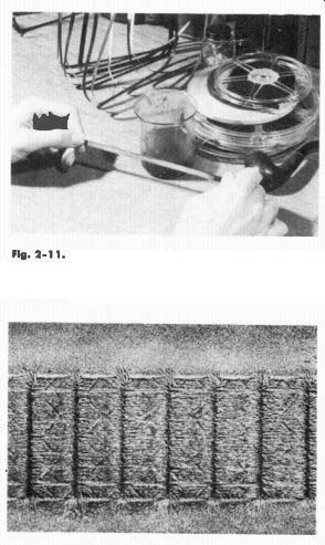
Fig. 2-11. After the Solution of Lighter Fluid and Carbonyl Iron Has
Dried, Very Fine Particles of Carbonyl Iron, Visible to the Naked Eye,
Will Remain Attached to the Tape.
Fig. 2-12. Microscopic Enlargement of Visible Magnetic Tracks.
The heavily magnetized intervals on the tape - the poles - attract the most carbonyl iron particles, appearing as narrow lines across the tape. The stronger the pole, the heavier the line. The lower the frequency of the current, the greater distance between lines. The actual wavelength of the original tone is equal to twice the distance between lines.
The Recording Process-- In summary, then, sound waves pulsate through the air, and cause the diaphragm in the microphone to vibrate accordingly. This produces corresponding electrical pulsations in the microphone which are boosted in strength by an amplifier. The amplified pulsations are then fed into the recording head where corresponding magnetic fields are created, which, in turn, leave their magnetic patterns on the tape.
The Playback Process --In playing back a recorded tape, the recording process is more or less repeated, only in reverse. During the recording process, an electric current in a coil was used to create a magnetic field. In playback, a magnetic field moved through a coil is used to create an electric voltage.
A basic principle of electricity is that a surge of electrical voltage can be generated by moving a bar magnet (or its surrounding magnetic field) through a coil. By moving a series of magnets of opposite polarity (or their fields) through a coil, an alternating electrical voltage will be produced. In the recording process, the tape was figuratively broken up into just such a series of short, permanent-bar magnets.
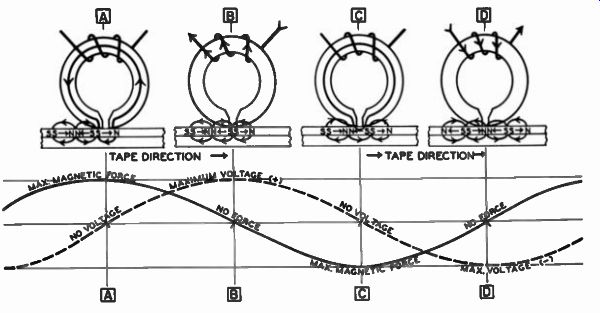
Fig. 2-13. The Playback Process.
What actually produces the voltage is the change in the magnetic field from positive to negative. The peak surge of current comes at the moment the polarity of the field is changing most rapidly. There fore, when the magnetic force in the head is maximum, no voltage is produced. See point A in Fig. 2-13. At the point where the polarity of the head is reversing, the maximum voltage is produced as shown at B in Fig. 2-13.
In the playback process, the bar magnets on the tape are not actually moved through the coil of the electromagnet. Part of the magnetic field of each bar magnet, however, is. What happens is that the iron ring of the electromagnet playback head temporarily routes the bar magnet's field through the coil.
In Fig. 2-13 at A, it can be seen that a north pole and a south pole are on either side of the gap. Normally, the lines of magnetic force stay close to the tape, but because it is easier for the magnetic, field to follow the iron ring (a much better conductor) than jump the air spaces at the gap, it does just exactly that.
At A, therefore, the magnetic force in the head is maximum but the voltage is zero.
When the tape has moved a fraction of an inch farther, as at B, a strongly magnetized line, a south pole, this time is at the gap. The iron ring of the electromagnet serves no useful purpose to the field, so it is ignored, and magnetic strength in the head is reduced to zero However, since this is the point where polarity of the head changes most rapidly, maximum voltage is produced.
But at C, the situation again occurs where one pole is on one side of the gap, and an opposite pole on the other. As in A, the magnetic field again takes the easiest route and flows through the soft iron ring. Maximum magnetic strength is produced in the head, but no voltage, since this is the point of alternation in the voltage wave from positive to negative.
At D, polarity of the head is again at the point of reversal, and consequently this sudden change in magnetic force results in the maximum surge of voltage. Since the surges of voltage alternate between positive and negative with the same frequency as that which was recorded on the tape, they can be amplified and fed into a loudspeaker to once again produce the original sounds.
-------