The tape recorder is not only an electronic instrument but is also mechanical in its operation. A television set, by way of com parison, consists of a series of electronic components and has, in theory, an eternal life. Tubes will wear out and require replacement. Occasionally a capacitor may break down. But there is no friction to limit its life. A tape recorder; however, is exposed to mechanical wear through its moving parts.
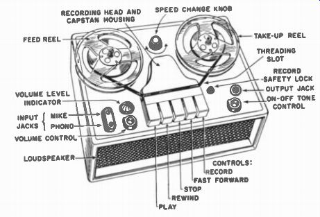
Fig. 3-1. A Typical Two-Speed Recorder with Principal Features Indicated.
The tape recorder operates on basically simple mechanical concepts. Most people with mechanical ability can study the mechanism and determine how it works and what each part is supposed to do. In many cases tape recorders are less complicated than record changers since there are no critical trip or cycling adjustments. However, many more stringent requirements are made on the tape mechanism.
The job of a record player is to rotate a disc, while the job of a tape recorder is to pull a tape, although both are designed to operate at a constant speed, the problem of pulling a tape past a magnetic head at a constant speed is considerably more complex than rotating a turntable. The disc player turntable serves as a flywheel, providing excellent instantaneous speed characteristics. A tape has very little inertia and its stabilization must come from an external flywheel.
A disc player turns only a single shaft at one, or at the most, three or four speeds. In contrast, the tape recorder capstan must often be able to operate at one of two different speeds. Its take-up reel operates at an infinite number of speeds within a given range. Its supply reel spindle must both rotate freely during certain operations and supply back tension during others, while having the ability to operate at high speed during rewind. All the shafts must be controlled by a system of clutches and brakes to facilitate rapid changes in tape direction and speed, still providing sufficient tension to avoid tape slack. The drawing in Fig. 3-1 illustrates a typical two-speed tape recorder with its principal features pointed out.
Primary Function of the Motorboard The motorboard is the actual mechanism of the tape recorder. The motorboard moves the tape past the magnetic head at a uniform rate of speed, winds it on a take-up reel, rewinds it, and has the ability to go fast forward. The fast forward and rewind functions enable the rapid location of any desired portion of the recording within the reel. A typical motorboard - top and bottom view - is shown in Fig. 3-2A and B.
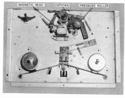
Fig. 3-2A. Top View of the Ekotope Motorboard with Top Plate
Removed.
Secondary Functions of the Motorboard
A definite evolution in simplicity of recorder operation and design can be traced from the early professional tape recorders to the machines of present construction. The complexity of early home-type tape recorders frightened most housewives intent on recording Junior's early prattlings. School teachers were equally alarmed but later proved to be one of the biggest single consumers of tape recorders during the early years of the magnetic recording industry's growth.
The threading of early tape recorders was a major undertaking, similar to threading up a motion picture projector. The magnetic tape was first wound about a series of guides, past the head, to the capstan, and then onto the take-up reel. (See Fig. 3-3.) Present day machines are threaded up by simply dropping the tape into a slot and winding it about the take-up reel as shown in Fig. 3-4.
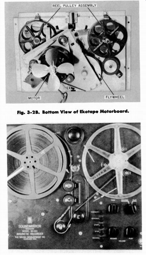
Fig. 3-2B. Bottom View of Ekotape Motorboard.
Fig. 3-3. The Threading Process of the Early Brush Recorder Model BK-401.
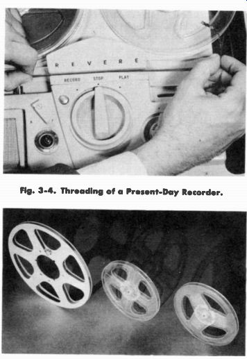
Fig. 3-4. Threading of a Present-Day Recorder.
Fig. 3-5. Three Types of Reels Now in Use.
There has also been a steady improvement in plastic reel design to make threading as simple as possible. The "Scotch" brand 7-inch plastic reel facilitates threading, for example, through its slot thread- up device. It is merely necessary to place the tape in a slot and rotate the reel a turn to anchor the tape. Ampex introduced to the 10 1/2-inch NARTB reel, the simplified loop, and post threading device. The RCA 7-inch reel follows the pattern used in many European Countries, with a slot running the entire length of the reel, as shown in Fig. 3-5.
There is also a well -developed trend away from knob type controls toward push-button or piano keyboard operation, again simplifying operation.
It was relatively easy for the novice to damage the earlier recorders through improper use. Today's recorder is ingeniously designed to make it as fool-proof as possible. If the wrong button should be depressed, it is not possible to damage the recorder or break the tape.
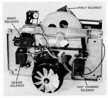
Fig. 3-6. The Ampro Recorder Uses Solenoid Controls for All Mechanical
Functions.
Solenoid controls are now incorporated on practically all of the professional recorders and some home-type, recorders. As an example, the Ampro recorder, shown in Fig. 3-6, uses solenoid controls for all mechanical functions. There are four solenoids in all used, and perform the following functions: (1) engages the rubber pressure roller against the capstan; (2) operates reel spindle brakes; (3) engages rewind drive; (4) engages fast forward drive. They also serve to disengage the rubber rollers when the machine is not in operation. This eliminates the possibility of accidentally leaving the capstan and rubber pressure roller engaged, producing flat spots on the rubber roller.
Earlier machines were also damaged by twisting control knobs too hard which bent lever linkages. It was also easy to spill tape from a reel, wrapping it around the capstan and pressure roller.
During rewind several recorders prevent excessive head wear by disengaging the magnetic head from the tape during fast forward or rewind. Magnetic tape construction has also been improved, eliminating the possibility of gumming up the record head with oxide accumulations which flaked off the tape. In addition, lubricants have been added to magnetic tape to minimize head wear and eliminate squealing and high-frequency flutter.
Most recorders incorporate a safety interlock on the record control so that the record button cannot be accidentally depressed, erasing the desired recording. Only when the safety interlock is disengaged, as shown in Fig. 3-7, is it possible to depress the record key.
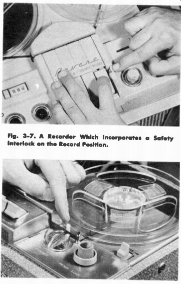
Fig. 3-7. A Recorder Which Incorporates a Safety Interlock on the Record
Position.
Fig. 3-8. This V-M Tape Recorder Employs an Automatic Shut-Off Switch.
The V-M model 700 tape recorder, shown in Fig. 3-8, incorporates an automatic shut-off switch. When the tape is threaded through the guides the shut-off switch is engaged. The recorder is then shut off automatically if the tape should break or the end of the reel is reached.
The ability to rewind the tape, operate the recorder at a fast forward speed, simple threading, and fool-proof controls are all secondary functions of the motorboard. The primary function of the motorboard is to provide a drive mechanism to move the tape past the magnetic head at as uniform a rate of speed as possible.
Speed Variations
The necessity of maintaining a constant speed is critical in all tape recorders and has required a major amount of engineering time to satisfactorily solve the problem. Simplified controls have added immeasurably to the tape recorder's popularity and have helped mushroom the magnetic recording industry's sales growth since 1947.
But the problem of simplifying the operation of the tape recorder is easy contrasted to devising a positive method of obtaining constant tape speed.
Long-Time Speed Variations
There are two types of speed variations affecting the performance of a tape recorder. They are: (1) long-time speed variations, and (2) instantaneous speed variations.
TAKE UP REEL SPINDLE RUBBER PUCK WHEEL ORIVE MOTOR CAPSTAN AND PRESSURE ROLLER FLYWHEEL
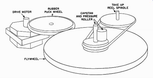
Fig. 3-9. A Typical Friction-Drive System.
Long-time speed variation is especially important in radio broadcast work. If a radio station makes a 29-minute recording, it is imperative that it last precisely 29 minutes, not running thirty minutes or only twenty-eight.
Among the reasons why tape does not run at a constant long-time speed are these: (1) Tape is pulled by a capstan and pressure roller which permits a certain amount of slippage to take place. (2) Tape itself expands and contracts with changes in temperature and humidity, causing the playing time to vary. (3) Tape recording mechanisms often use non-synchronous or induction-type motors in which speed is affected by variations in load and line voltage. Even on machines using synchronous motors, the capstan flywheel assembly is generally driven by a rubber puck drive or belts which are not positive in their drive. (See Fig. 3-9.) In tape recorders the tape is pulled by a capstan, a shaft around which the tape is wrapped. Therefore, the tape is not positively driven. In a positive drive system, teeth ¡none gear engage teeth in another, or teeth on a sprocket engage perforations in a film, providing a drive in which slippage is impossible. In a friction drive, one roller turns another roller, both rollers having a smooth surface. Traction is obtained by friction and is not positive. In any type of friction drive system, a certain amount of slippage is always present. Gear drives introduce flutter which require an elaborate filtering mechanism to remove.
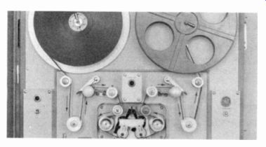
Fig. 3-10. This Westrex Magnetic Film Recorder Uses a Positive-Drive
System.
Excessive cost of positive drive systems and perforated film for these machines is the prime reason for using friction drive and tape for most recording applications. An Ampex 300, costing approximately $1,700, will give comparable recording quality to the Westrex magnetic film recorder, for motion picture use shown in Fig. 3-10, which incorporates a positive drive system, and leases for $8,500 for 12 years. For 33 minutes of recording, 35 mm magnetic film for the Westrex costs about $125 while the quarter-inch tape for the Ampex Costs $3.30. Both will do approximately the same recording job. However, positive drive is necessary in motion picture recording to have sound synchronized exactly with the lips of the actors.
Expensive tape recorders designed for critical broadcast work generally have speed variations of only a few seconds in a 30-minute recording. In the less expensive home machines the speed variation in extreme cases might run as much as several minutes in a 30-minute recording.
Apart from the necessity of maintaining exact speed in professional broadcasting and recording work, long-time speed variations also affect true pitch. Although no wow or flutter is present, if a recorder is running slow the pitch will be low. If music is played at other than true pitch, the effect is disconcerting. Even though the variation is slight, musicians and music lovers with a trained ear are able to detect the pitch change.
Instantaneous Speed Variations
Another critical feature of a tape drive mechanism is the importance of instantaneous speed stability. Instantaneous speed variations are of an exceedingly short duration, generally less than a very short fraction of a second or, at the most, a half a second. Speed variations of a short duration cause wow and flutter, twin menances to good recording results. The wow meter, shown in Fig. 3-11, will measure these variations in speed which are then expressed in percentages.
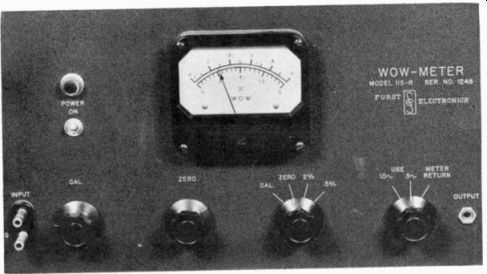
Fig. 3-11. A Wow-Meter Which Measures Minute Variations in Tape Speed
and Expresses Them In Percentages, Manufactured by Furst Electronics.
Among the factors causing instantaneous speed variations are these: (1) Flat spots which develop on the rubber rollers. (2) Slipping of the drive rollers and tape on the capstan. (3) Sticking of the tape to the heads or guides. (4) Bent or eccentric shafts. (5) Motor "hunting" or "clogging." (6) Irregular feed or take -up reel operation.
Wow and flutter are particularly noticeable even to untrained ears and have a very disturbing quality. It is without question the most objectionable feature of low-priced tape recorders. It is interesting to note that the ear can detect instantaneous speed variations of as little as one-tenth of one percent. Many of the home type tape recorders have instantaneous speed variations above one-half of one percent.
Wow is a relatively low frequency speed variation, noticed especially on sustained notes such as in piano or organ music and chimes. When wow is present, a musical note that is held will sound unsteady. Its pitch will waver, producing a very irritating effect.
A still shorter speed variation will result in flutter. Flutter causes the sound to be of a garbled nature, again showing up in piano music especially. Often when a recording does not sound clean the cause will be flutter, even though it may not be diagnosed as such. High-frequency flutter is often mistaken for other types of distortion.
Capstan Drive
The very heart of a tape recorder is the capstan drive. The tape is pulled by a roller pressing the tape against a rotating shaft. The rotating shaft is known as the capstan. In many older machines rubber or composition covered shafts were employed to pull the tape. The rubber capstan was attached to a common shaft with a flywheel and was motor driven. The early Brush, Eicor, and International Electronic Company tape recorders, for example, used a rubber roller to pull the tape. The early Eicor tape recorder is shown in Fig. 3-12.
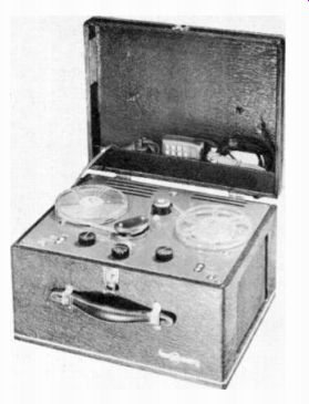
Fig. 3-12. An Early Eicor Tape Recorder.
However, the introduction of lubricated magnetic tape in 1949 necessitated a more positive drive and required the use of a pressure roller against a steel capstan. This is shown in the photo of the Magnecord model PT6-A (Fig. 3-13). Importance of a Large Capstan Diameter Because of necessary physical stability, a fairly large diameter capstan is required. If the capstan is at all eccentric it will pull the tape faster at one point in its revolution than at another, introducing serious wow and flutter. A small capstan will also have a tendency to whip. To obtain the required rigidity, it is generally necessary to use large diameter capstans.
Another reason for a large diameter capstan is to minimize speed variations caused by differences in the caliper of magnetic tape.
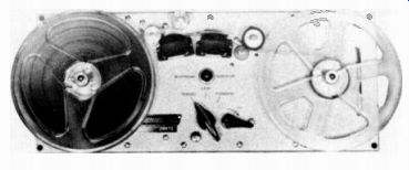
Fig. 3-13. The Magnecord Model PT6-A Tape Recorder.
Since magnetic tape is wrapped around the capstan, the portion of tape next to the capstan will be compressed and the portion of tape away from the capstan will be elongated. The velocity of the tape will be at some point midway between its two surfaces. Therefore, if the tape thickness should vary, its velocity will also vary. But if the capstan is large in comparison to the tape thickness, variations in tape thickness will be, for all practical purposes, negligible.
However, large capstans have one main disadvantage. If the capstan size is increased, the flywheel size must also be large, since more inertia is needed to stabilize a large, slow speed capstan than one that is small but high speed. The capstan size of .most recorders varies from slightly under an eighth of an inch to approximately five-eighths of an inch.
Methods of Motor Drive
In order to stabilize the capstan's rotation and provide the most uniform tape speed possible, a flywheel is attached to the capstan shaft. The motor then drives the flywheel by one of the following methods: (1) Puck drive. (2) Belt drive. (3) Direct drive.
Puck Drive
The high speed of the motor shaft requires that some method of speed reduction be incorporated into the drive system. The puck drive is a method of driving the rim of the flywheel by a friction process. In some mechanisms such as the Ampex 300, the flywheel is equipped with a rubber tire and is driven directly by the motor shaft as in Fig. 3-14A. Another type of puck drive, shown in Fig. 3-14B, which is used by nearly all home-type recorders, employs an intermediate puck roller which in turn drives the flywheel. The rim -drive method, although lacking some of the possibilities of the other drive methods, results in very satisfactory performance even when produced to meet competitive prices.
For rim-drive applications, the motor shaft is usually equipped with a metal pulley of small diameter. This pulley is a bushing positioned onto the shaft by means of a set screw.
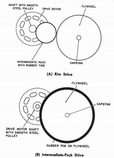
(A) Rim Drive (B) Intermediate-Puck Drive
Fig. 3-14. Two Methods of Puck Drive.
For the intermediate puck drive system a rubber tired wheel called the idler wheel (see Fig. 3-15), is mounted so that the motor pulley will drive it. The idler wheel, in turn, will drive the capstan flywheel rim. The center bearing of the idler wheel is mounted on a plate. Although there are design variations in the mounting of this bearing, the purpose of each is threefold: (1) Insure a correct wedge angle of the idler wheel between the flywheel rim and the motor pulley exerting enough traction to transmit the torque and yet not stall.' (2) Keep the idler wheel movable horizontally so that spring tension may be applied to the bearing mounting in the direction of the wedge angle, providing constant pressure of the idler wheel against both the flywheel rim and the drive pulley, and (3) Maintain alignment of the idler wheel in a vertical plane, with the motor pulley and the flywheel rim. An exploded view of a typical bearing mounting system is shown in Fig. 3-16.

Fig. 3-15; Fig. 3-16. Exploded View of a Typical Bearing Mounting.
The diameter of the motor pulley is determined by the diameter of the flywheel, the speed of the motor shaft, the capstan diameter and the loss in working the rubber of the drive tire. The diameter of the idler wheel does not affect the speed ratio but is selected and designed according to the curvature which will best deliver the torque required.
Due to the sturdiness of the motor itself, the greatest source of trouble in rim drive motors is associated with the idler drive wheel. All parts of the idler wheel mounting should be inspected for extraneous material or gumming. The parts should be thoroughly cleaned and re-lubricated, if needed, in order to prevent speed reduction. The sleeve bearings of the idler wheel are usually lubricated through a felt washer.
This bearing is in most cases lubricated for the life of the motor, but if it is felt necessary to add lubrication, it should be done with extreme care to avoid over -lubrication.
The tire of the idler wheel is of natural or synthetic rubber and after being cemented to the idler wheel, it is ground with a crown to be absolutely concentric with the axis of the idler stud. The radius of the crown and the hardness of the rubber are design factors dependent upon the torque required. For this reason, it is advisable if a damaged tire is encountered, to replace the entire idler wheel with an exact duplicate.
Puck drive systems give very good instantaneous speed regulation, tending to reduce wow and flutter. However, the condition of the surface of the rubber rollers is of utmost importance. Indiscriminate lubrication or an "oil bath" treatment is a very hazardous practice. Oil has a tendency to creep or run over surfaces, spraying the rotating puck with a minute amount of oil. This results in slippage and deterioration of the rubber parts. One of the commonest troubles encountered is slippage due to a film of oil on the idler tire.
If slippage results from excessive oil, it is best to replace the idler wheel and pucks after first cleaning all nearby surfaces
These include the flywheel rim, motor pulley, and idler plate. Use a cloth moistened with carbon tetrachloride. If the idler wheel is not replaced wash the entire wheel in carbon tetrachloride, making sure to remove any oil in the crevices between the rubber tire and the metal of the wheel.
Since in a puck drive one of the rollers must be rubber in order to get friction, there is danger that flat spots may develop from leaving the roller engaged with one of the shafts, thereby indenting the rubber. When a rubber roller develops flat spots, it makes a disagreeable thumping noise and introduces wow each time the flat spot rotates. This dent can sometimes be removed or minimized by running the recorder for half an hour before using.
Time and wear will develop a glaze on the surface of the rubber, resulting in slippage. The glaze may be removed by carefully holding a piece of fine sandpaper against the tire while the idler wheel is being driven by the motor. However, this practice is usually not worthwhile since, by the time a glaze develops, the material has probably deteriorated to a point where wheel replacement is advisable.
Flutter, a tremulous quality of reproduced sound, often results from modulation by motor noise. This is caused by : (1) Insufficient mechanical isolation between the motor and the remainder of the drive system. (2) Excessive vibration of the motor due to unbalance of its rotating parts.
Belt-Drive Systems
The second major drive system is the belt drive. Two types of belts are employed: composition and rubber.
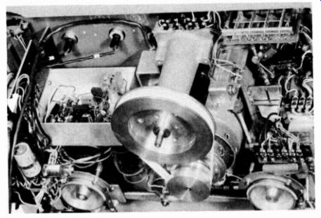
Fig. 3-17. The Presto SR11 Uses a Woven Flat-Belt Drive from Motor to
Flywheel.
The composition belt is flat in construction, running between the motor and the flywheel. Generally, a tension roller arm is also employed to keep the belt taunt. This is a comparatively expensive drive because an extra idler roller is required. However, this is fundamentally a good drive system, making for excellent speed stability. The composition belt is used in the Presto professional recorder and the Ampex 600. The Presto model SR11 is shown in Fig. 3-17.
The other type of belt is a round rubber belt, also linking the motor to the flywheel. The use of a rubber belt means that an idler is not needed because the rubber has enough tauntness to remain tight. However, the rubber belt in time will become loose and cause slippage.
Hard spots may develop, also introducing wow. When slippage develops, the rubber tends to wear away and fills the recorder with rubber shavings. The round rubber belt is used to drive the capstan on the Brush Soundmirror and is now also used in the new Ampro recorder and the Presto long-play recorder units. The Ampro recorder is shown in Fig. 3-18.
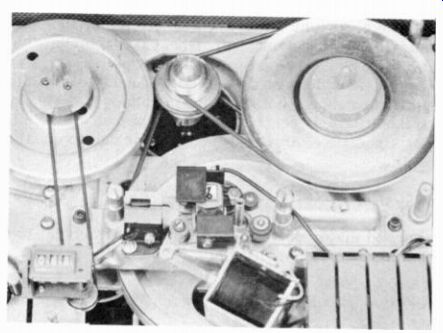
Fig. 3-18. The Ampro Model 755 Uses o Round Rubber Belt Drive.
Direct-Drive Systems
The third type of drive system, becoming increasingly popular in professional recording equipment, employs the motor shaft as the capstan shaft. If there is a flywheel in the system, the flywheel is attached directly to the motor shaft. This drive operating directly from the motor, has many advantages since there is only one rotation shaft with no transmission of power from one shaft to another. Therefore, there is no need for rubber puck rollers which may become dented and introduce wow. There are no belts to stretch and develop hard spots.
However, to rotate the capstan and have a reasonable capstan diameter, relatively slow speed motors must be used. For example, to operate at 7 1/2 ips, and have a capstan diameter of approximately .24 inches, one needs a 600-rpm motor which is expensive, large, and heavy. Professional equipment can tolerate a motor of this type. However, its cost, size, and weight preclude its use in portable home-type equipment.
Still another disadvantage of the direct drive is that motor irregularities in its core structures and variations in damping as the motor armature rotates tend to introduce a certain amount of wow and flutter in the tape. These irregularities, however, can generally be damped by careful design of the motor. By adding flywheels, excellent flutter characteristics can be obtained.
Induction Motors
Any drive system can use two types of motors: induction or synchronous. A conventional induction motor has, generally, fairly stable speed characteristics. It has good instantaneous speed regulation, including very little flutter and wow. It is inexpensive, compact, runs relatively cool and gives a lot of power for its size. Non-synchronous or induction motors, however, are subject to speed variations caused by changes in load and line voltage.
Synchronous Motors
The other type of motor, used on professional equipment only, is a synchronous motor. The synchronous motor has absolutely perfect long-time speed regulation since its speed is controlled by AC power alternations. However, it tends to introduce a certain amount of instantaneous speed variation during its rotation, resulting in some flutter. It is an expensive motor, runs quite hot, and is large for a given amount of power.
Take-Up Reel Drive
The capstan, of course, is used to pull the tape at a constant speed past the magnetic head. However, tape moving at a constant speed must then be spooled onto a take-up reel. Because the tape goes from a small diameter at the beginning of the reel to a large diameter at the end, the reel speed must change since the tape speed remains constant. The rpm of the reel changes considerably from a large to a small diameter. Therefore, all recorders employ some type of variable-speed drive.
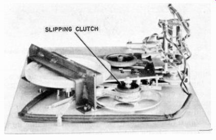
Fig. 3-19. The Ekotape Model 101 Slipping-Clutch Variable Speed Drive.
The most common variable speed drive is the slipping clutch used in the Ekotape model 101 shown in Fig. 3-19. Generally, the clutch consists of a rotating disc that is driven at a constant speed, often by the same motor that drives the capstan. Next to this disc is placed a piece of felt. The felt slips on the disc and drives another disc which, in turn, drives the reel shaft.
The slippage between the drive disc, the felt, and the reel disc applies a more or less constant torque on the take-up reel. This constant torque is something of a disadvantage, since when the reel is nearly empty, the lever arm is short and tension on the tape will be high. However, when the reel is nearly full, tension on the tape will be very low since the lever arm is long.
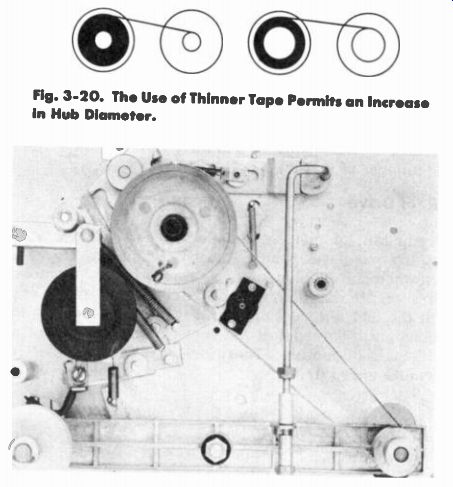
Fig. 3-20. The Use of Thinner Tope Permits on Increase in Hub Diameter.
Fig. 3-21. The Pentron Model 9T-3C Uses a Cloth Belt to Drive the Take-Up Reel.
Because the tape is being pulled past the head by a capstan, in theory the tape should be moved at a constant speed. However due to the change in reel diameter, the tape is under heavy tension at one time and under light tension at the other. The tape tends to slip by the capstan at a slightly faster rate under heavier tension. Because of this variation, it is desirable to have constant tension on the take-up reel. The slipping clutch device as used on most tape recorders does not provide, however, constant tension. To help solve this problem tape manufacturers have developed thinner tape, permitting an increase in the hub diameter of the reel, thus reducing tension difference between the inner and outer reel diameter as illustrated in Fig. 3-20. The other method of revolving the take-up reel is by use of a stalled induction motor. This method is used by several of the professional recorders such as the Ampex. It is also used on such home recorders as the TDC model 130. In this method of variable speed drive, the reel is attached to the motor shaft or is driven by the motor shaft. The motor is, in turn stalled, not being allowed to run at its full speed. Therefore, the motor exerts a torque on the reel. By careful design of the motor , a nearly constant tension can be maintained regardless of how full the take-up reel may be. Also, the motor take-up is more dependable, since it is unaffected by changes in temperature, humidity, and lubrication as is the slipping felt-clutch device.
A third method of driving the take-up reel is by a slipping cloth belt on a polished pulley. The Pentron, Crescent and Telectrosonic use this system. The belt is driven at a high rate of speed around a very smooth pulley which, in turn, drives the take-up reel. The belt drive suffers many of the same problems as the felt clutch since the tape tension will vary from time to time depending on lubrication, temperature, and humidity conditions. The Pentron model 9T-3C is shown in Fig. 3-21.
Rewind and Fast-Forward Mechanisms
The remainder of the motorboard mechanism is designed to rewind the tape. In addition, practically all tape recorders incorporate a fast- forward speed, enabling the tape to move at a higher than operating speed, facilitating rapid location of selections within the reel of tape.
During both fast forward and rewind, very little back tension is applied to the feeding reel. This allows the tape to be moved at a high speed with a minimum of mechanical power.
In home recorders, generally a mechanical linkage shifts the reel shaft or puck shaft into position to be driven by the motor. By using a minimum amount of mechanical power with little back tension, a "soft" tape wind is achieved. It is essential that tapes be softly wound to prevent physical distortion in which one edge of the tape is stretched.
If a tape which is tightly wound is subjected to a sharp change in humidity or temperature, tremendous tape tensions will be built up on the reel. Each layer of tape contributes a progressively stronger pressure on its adjoining inner layer which will often stretch the tape beyond its yield point, thus permanently deforming its shape. In extreme cases of physical distortion, the cumulative pressure becomes so great that the plastic reel hub shatters under the tremendous tension.
It is regrettable that the more expensive professional machines are the worst offenders in respect to tape distortion. These recorders, using a direct-coupled motor drive for either rewind or fast forward, invariably wind the tape "hard." The direct motor drive exerts a more or less constant tension on the tape during operation, thus building up considerable pressure with each turn of the reel.
Many tape engineers feel that the constant-torque reel drive used on most home recorders contributes to the best tape storage, since the outer turns are wound with far less tension than the inner turns. However, as pointed out earlier in this section under capstan drive, the professional recorder manufacturers are faced with the necessity of obtaining constant tension throughout the reel to eliminate capstan slippage. There is little doubt that the manufacturers of professional machines, faced with a choice between two evils, favored a direct coupled motor drive with little capstan slippage over a constant torque reel drive providing a soft tape wind.
Two-Speed Drive
In the professional field, two tape speeds are becoming standardized throughout the industry. The 15 -ips speed is being widely used for original recording where the highest possible fidelity is desired. However , with the tremendous improvement in performance at 7 1/2 ips, this speed has been widely accepted as standard for the bulk of broadcast work. Therefore, the professional studio machine should have both speeds.
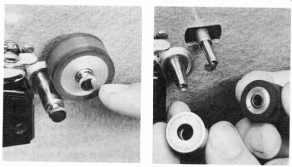
Fig. 3-22. The Speed of the Magnecord Model PT-6 is Changed by the Physical
Transfer of Capstans. (A) Capstan and Pressure Roller to be Removed.
(B) Replacing with Capstan and Pressure Roller of Different Size.
In most professional equipment the speed change is now accomplished by means of switching the fields in the synchronous drive motor. Since most professional machines use this type of motor, it is possible to change from a four-pole motor, running at 1800 rpm, to an eight-pole motor, running at 900 rpm. A synchronous drive motor with six poles, running at 1200 rpm, can be changed to a twelve pole motor running at 600 rpm. The speed change is simply accomplished by flipping a switch which connects the proper number of motor fields in the circuit.
By contrast, the speed of one make of professional recorder can be changed by the physical transfer of capstans as shown in Fig. 3-22. A removable pressure roller and capstans of different diameters are used for different speeds. This method, while perhaps bothersome and time-consuming, serves the purpose. A well machined tapered shaft is used, making the removal and fitting of the capstan easy. However, the pressure of dirt on the capstan shaft will make the capstan eccentric with resulting wow and flutter.
Among the home recorders, both the 7 1/2-and 3 3/ 4 -ips speeds are of vital importance. The 7 1/2-ips speed is generally used for higher quality musical recordings while the 3 3/4-ips speed serves primarily for voice applications. It is true that some recorders operating at 3 3/4 ips give better performance than others operating at 7 1/2 ips, but this depends upon the design and precision of the recorder itself.
It is more difficult to obtain good performance at slower tape speeds for two reasons: First, the high frequency response is limited and the output is reduced. This subject will be fully treated in the TOP VIEW

Fig. 3-23. Changing Speed by Changing the Position of the Intermediate
Pucks.
section on magnetic heads. Second, the wow and flutter is increased since there is less inertia in tape systems operating at slower speeds. Also, any minute variation in tape speed has a tendency to adversely affect the recording when the tape is traveling at slow speeds.
In the home recorder field, the majority of recorders change speed by changing the position of the intermediate puck from one diameter on the motor shaft to another as illustrated in Fig. 3-23. Generally, the intermediate puck is moved between two steps on the motor shaft of different diameters.
While this system works very well as a speed changing device, the method of shifting the pulley is of great importance. On some recorders the pulley is actually forced over the edge of the step. If the recorder is in a neutral or off position, the speed change can be easily and safely accomplished. However, if the recorder is running, the pulley will severely nick the intermediate puck roller. The nicked edge will result in serious wow and flutter.
The more desirable method of speed change used in many of the newer home recorders is accomplished by actually removing the intermediate puck from both the motor drive shaft and the flywheel. The intermediate puck is then shifted to its new position and is re-engaged, eliminating any possibility of nicking its edge.
In most home recorders the intermediate puck roller is the heart of the drive system. The smoothness and consistency of the surface about its center axis is all important in keeping wow and flutter to a minimum. Care must be exercised in operating those machines which, in changing speeds, do not remove the intermediate puck from the shaft, motor pulley, and flywheel. It is a wise precaution to check the type of speed change used by the recorder before changing speeds.
Several home machines still change speed by varying the capstan size. However, this method is gradually being discarded. Because of cost considerations, in home machines a tapered shaft, precision- machined, can not be used. Consequently, if the capstan fits well it is difficult to remove and put on. If the capstan is easy to remove, the fit is so poor that the capstan will be eccentric and wow and flutter will develop.
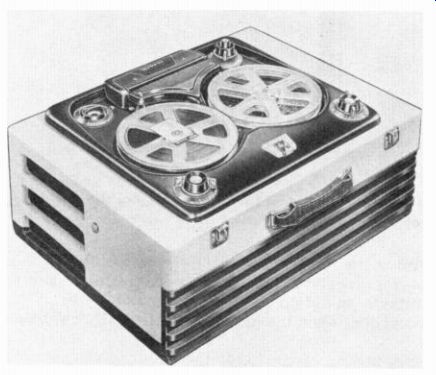
Fig. 3-24. The Webcor Model 2130 Incorporates a Dual Direction Design
Which Permits Tape Operation in Either Direction.
Dual-Direction Mechanism
A number of recorders are specially designed for longer playing time, continuous operation, repetitive loops, etc. One very popular home machine, the Webcor (Fig. 3-24), incorporates a dual-direction design which permits operation in both directions.
In dual or half-track recording, as used on this machine, one track is recorded in one direction, the other track in an opposite direction. This eliminates turning over the reel when the end of the tape has been reached as is customary in other dual-track recorders that operate in only one direction.
Braking Mechanisms
When the recorder is put in the stop position the reels must break as rapidly as possible without causing damage to the tape. Generally, the breaks consist of a metal wheel which engages a rubber rim on the reel shafts. Also, a rubber or felt pad can be used which rubs on a metal disc on the reel shafts.
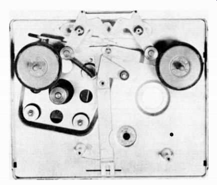
Fig. 3-25. Brake Mechanism of the Revere Model T700.
In normal operation the brakes are removed, but in the stop position they are suddenly released and applied to the revolving reel spindle shafts, causing them to abruptly halt. The brake mechanism of the Revere model T700 is shown in Fig. 3-25. It is always important that the feeding reel, the reel from which the tape is being drawn, be stopped first. Otherwise tape spillage will result.
The adjustment of the brakes is critical in many machines to prevent tape spillage and still not cause physical damage or stretching of the tape. Several machines, such as the Pentron, use no brake action whatsoever. The tape is braked only by reversing the direction of drive on the reel spindles. An interesting approach to braking is also found in the new Crescent recorder which applies braking pressure toward both reel spindles while stalling the motor, rapidly halting the tape with no danger of spilling or breaking the tape.
Position Indicators
Position indicators are becoming increasingly common. They are counters that are driven by the feed or the take-up reel and count the revolutions of the reel. This feature enables rapid location of selections within a reel of tape. Fig. 3-26 shows the position indicator on the Ampro recorder.
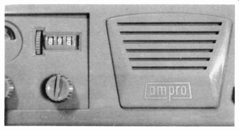
Fig. 3-26. Position Indicator Used on the Ampro Model 755.
Maintenance
Since a recorder motorboard is a mechanical device with shafts and bearings, occasionally a drop of oil is required to keep all parts exposed to friction or wear turning freely. Most recorders, however, require very little oil. Because of the slippage problem caused by oil on the rubber rollers, excessive oiling is a real threat.
Most recorder bearings are manufactured from a power bronze material, such as "oil-lite". This is a very dependable, life-long bearing in which oil is actually impregnated into the powdered bronze bearing material. Since most recorder shafts turn at slow speeds, they will last a long time.
Like any mechanism, the biggest menace to a recorder is dust, dirt, and grit particles working between the shafts and bearings, scouring them and causing wear. To keep any tape recorder at peak operating performance, the motorboard mechanism should be kept clean and free from dust and grit. When worn, an occasional shaft or bearing may require replacement.
-------