The drive motor is one of the most critical parts of the drive mechanism since it must supply the power which drives the tape. The main requirement of any tape-recorder motor is that it hold a constant, normal running speed. The quality of the recording and subsequent playback is, of course, dependent upon the linear velocity of the tape which is, in turn, dependent on the rotational speed of the capstan.
Any deviation in the capstan rotation speed will affect tone or pitch. The audiophile with the legendary "golden ear" will easily recognize that the tape speed is not perfect, even though the variation may be exceedingly minor.
Other requirements for motors are that they resist overheating despite being small and lightweight. In addition, the suitability of the tape-recorder motor is determined by such factors as elimination of stray magnetic fields, ruggedness, dependability, silent operation, and infrequent maintenance.
Two types of motors are used in tape recorder design: the induction motor and the synchronous motor.
Home Recorder Induction Motors
The vast majority of small home recorders use as their drive motor an induction motor of the single-phase shaded-pole type. The shaded-pole induction motor provides an acceptably constant running speed for home recorders, and is quite small, compact, simple in design, and very inexpensive. With normal use the motor is very rugged and practically indestructible. A typical induction motor is shown in Fig. 4-1.
The induction motor is able to withstand relatively long periods of "stalled" operation without serious overheating. This condition may occur when some part of the drive mechanism jams and the whole system, including the motor, is blocked until it receives attention.
Motor speed, which is stepped down to capstan speed commonly by rim driving is, in the majority of recorders, slightly under 1800 rpm. Average power consumption is of the order of 60 watts.
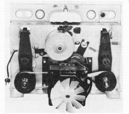
Fig. 4-1. A Typical Single-Phase, Shaded-Pole Type Drive Motor- Shown
is the Crescent Model 900 Series.
Components of Induction Motors
An induction motor is composed of a stationary field structure, the stator, and a rotating element, the rotor as shown in the drawing in Fig. 4-2. The stator consists of coils which are wound on projecting iron cores or poles. The open end of each core, the pole face, extends toward the rotor. The pole faces partially encircle the rotor.
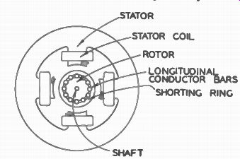
STATOR; STATOR COIL ROTOR LONGITUDINAL CONDUCTOR BARS SHORTING RING SHAFT
Fig. 4-2. Construction of on Induction Motor.
The rotor is mounted in the center of the fields. This rotating element is a cylindrical, laminated, iron core carrying lengthwise conductors in slots on its surface. The conductors are shorted by a ring at each end of the core.
The purpose of the stator is to provide, although remaining stationary, a revolving magnetic field around the rotor. The magnet is placed so that its pole is near the rotor conductors, and the magnet is revolved around the rotor. As the magnet revolves, its magnetic field revolves with it, causing the lines of force to cut the rotor conductors.
How the Induction Motor Works
The induction motor works with a relative slippage between the rotating magnetic field, set up in its stator or field coil, and the rotation of the armature or rotor.
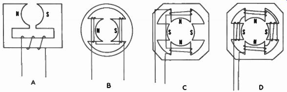
Fig. 4-3. Methods of Stator Construction. (A) Single-Coil, Two-Pole Stator.
(B) Two-Coil, Two-Pole Stator. (C) Two-Coil, Four-Pole Stator. (D)
Four-Coil, Four-Pole Stator. The Magnetic Polarization Shown is That Which
Would Exist Once During Each Cycle of the Applied Voltage.
As we have seen, the induction motor consists of two main parts, the stator and the rotor. The stator, the stationary part of the motor, is fastened to the frame. The rotor or armature, the rotating member of the motor, is supported by bearings on each end and supplies the power to the recorder.
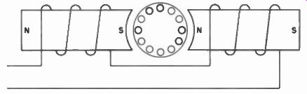
Fig. 4-4. The Number of Poles Determines the Speed of the Motor. In a
Two-Pole Motor the Magnetic Field is Reversing Between Each Pole at 3600
Times a Minute.
The stator is equipped with magnetic poles around which are wound the field coils. These poles are electromagnets and, of course, are supplied by alternating current going on and off at the rate of the line frequency or are going through a complete cycle, north and south poles, 60 times a second. (See Fig. 4-3.) The number of poles determine the speed of the motor. It is easy to see that in a two-pole motor the magnetic field is reversing between each pole at 3600 times a minute. (The alternating current is changing polarity 60 times a second, and there are 60 seconds in a minute.) Therefore, in a two-pole motor with the magnetic polarity changing 3600 times per minute, the armature would normally try to make 3600 revolutions in a minute in an attempt to keep up with the magnetic field as illustrated in Fig. 4-4.
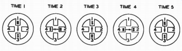
Fig. 4-5. A Four-Pole Motor, Instead of Turning a Complete Revolution,
Needs to Turn Only Half a Revolution Before it Meets a Pole of Opposite
Polarity.
In a four-pole motor, illustrated in Fig. 4-5 the armature, instead of turning a complete revolution, needs to turn only half of a revolution before it meets the pole of opposite polarity. Consequently, it rotates only 1800 times a minute.
A six-pole motor rotates 1200 times a minute and an eight-pole motor rotates 900 revolutions per minute. However, as we have seen, the armature attempts to keep up with the rate of magnetic polarity change, trying to rotate at the same speed as the magnetic field. The speed of the rotating field is known as the synchronous speed. It depends upon the frequency of the applied voltage and the number of poles in the motor.
There is a constant difference between the rotation of the magnetic field and the rotation of the armature. Consequently, the rotor speed can never reach the speed of the revolving field because it is necessary that the rotor bars continue to cut the flux of the stator field. The difference between the rotor speed and the synchronous speed of the revolving magnetic field is known as the "slip" of the motor.
The slip between the synchronous speed of the magnetic field and the rotation of the armature is just enough to create a current in the armature. That is, if the armature were to run at the same rate as the rotation of the magnetic field, no current would be created. However, the greater the difference between the speed of armature rotation and the synchronous speed of the revolving magnetic field, the greater the current and the greater the torque within its operating range of speeds.
The slip may be as high as 40% of the synchronous speed, depending on the load, the friction in the drive system, and the condition of the bearings. With increase in load, the speed is slower.
Therefore, more flux lines are cut and greater torque is developed, depending upon the speed-torque characteristics of the motor.
With the input line frequency of 60 cycles, the synchronous speed of a two-pole motor is 3600 rpm and that of a four-pole motor is 1800 rpm. The slip of the average two-pole motor is greater than ...

Fig. 4-6. Position
of Pole-Shading Coil, or Ring, in Pole Face.
... that of the four -pole type. Shaft speed of a two -pole motor will probably be within a range of 3000 to 3500 rpm and of a four-pole motor between 1400 to 1750 rpm.
This is, essentially, the operation of the induction motor. Various means have been devised to start the induction motor and get it rotating.
It can be seen that if the armature is standing still, the magnetic fields are simply reversing. Consequently, there is no incentive for the motor to turn. This necessitates placing additional poles in the motor structure which become energized at a slightly different time or out of phase with the applied voltage to the regular poles.
Single-phase induction motors are named and distinguished from one another according to the starting method or phase shifting. A phase shift in a winding can be accomplished by means of a series capacitor or by making one winding with more inductance than another winding, or finally, by means of shading a pole.
Most tape recorder motors use the shaded pole principle. Starting torque is provided by pole shading, effecting a movement of magnetic flux across the pole faces of the field structure. This is done by notching each pole face and inserting a copper ring which encircles approximately one -third of the pole face as shown in Fig. 4-6.
The copper rings oppose a change in the magnetic field. Thus, when the main pole becomes north, the secondary pole created by the slot in the coils refuses to become north. Consequently, when the main pole is being reduced from north and is moving toward south, the little slotted area becomes north, giving a rotational field which starts the motor.
The four-pole motor is more satisfactory for use in tape recorders because it gives a lower external magnetic field. Two-pole motors have a tendency to induce a hum field in the magnetic head.
Other advantages of the four-pole motor include the slower speed reduction necessary to drive the capstan. Also, quieter operation is achieved due to a lower vibration frequency, and the use of a larger rotor which can be dynamically balanced more easily, thereby further reducing motor vibration.
The four-pole, two-coil motor is seldom used in tape recorders due to its excessive external magnetic field which is almost as bad as the two-pole design. The four-pole, four-coil motor is more commonly used.
How the Synchronous Motor Works
The second type of motor used in tape recorders is the synchronous motor. In the synchronous motor the armature rotor travels at exactly the same rate of speed as the magnetic field. With the exception that the shaded pole principle is not used (either the series capacitor or high inductance winding is common), the stator or pole structure is exactly the same as in an induction motor. The difference lies in the speed of the armature.
Fig. 4-7. Construction of Rotor for (A) Induction Motor and (B) Salient
Pole, Synchronous Motor.
A synchronous motor, true to its name, runs at an exactly synchronous speed. If the magnetic field of the stator is rotating at 1800 rpm, the armature also will rotate at exactly 1800 rpm.
Synchronous armature speed is achieved by two methods. In the salient pole synchronous motor illustrated in Fig. 4-7 , the armature is exactly the same as in an induction motor, using the same type of core structure that supplies torque. However, as shown in the com parison of the two armatures in Fig. 4-7A and B the armature is milled with flat spots on it. As the motor comes up to speed, these flat spots will lock into the rotation of the magnetic field. Thus, an easier path for the magnetic field is supplied through one side of the armature than the other. The armature will tend to follow the magnetic field exactly rather than slip behind it, thereby running at synchronous speed.
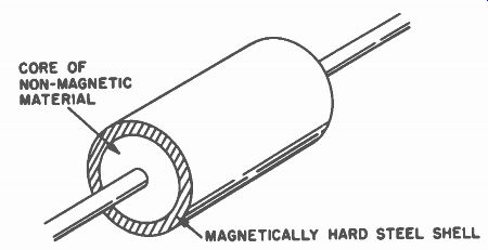
CORE OF NON-MAGNETIC MATERIAL MAGNETICALLY HARD STEEL SHELL
Fig. 4-8. Construction of Rotor of Hysteresis Synchronous Motor.
The other type of synchronous motor , the hysteresis synchronous motor, is commonly used in present-day professional-type recorders.
In a hysteresis synchronous motor, the armature is surrounded by a thin ring of very magnetically hard material (see Fig. 4-8) , which becomes highly magnetized. As the motor comes up to speed, the rotating flux of the last cycle, before locking into synchronization, will magnetize one end of the armature north and one end of the armature south. These poles will lock in with the rotating magnetic field, and the motor will run at synchronous speeds.
The synchronous motor has the advantage that its speed will never vary. The speed of the hysteresis synchronous motor will be as constant as the line voltage, and the recordings will last exactly the right length of time, providing all of the other drive system parts are functioning without slippage.
Induction Vs. Synchronous Motors
A synchronous motor tends, however, to have less desirable instantaneous speed characteristics. For example, the synchronous motor has trouble "hunting" or vibrating about a common speed which introduces some flutter and wow into the recordings. On the other hand, the induction motor is not a constant speed motor and is always slipping somewhat. The rate of slip may be different under low voltage than high voltage. The voltage applied to the induction motor changes its speed, hence introducing timing error.
However, the induction motor has very constant instantaneous speed characteristics, introducing little wow or flutter to the system.
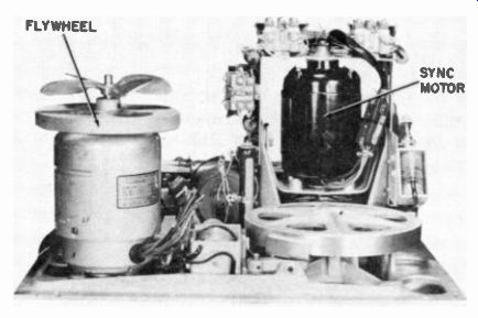
Fig. 4-9. Underside of the Ampex Model 400 Motor board.
The synchronous motor is most widely used on professional recording equipment where elaborate methods are used to insure a constant speed, eliminating both instantaneous and long term speed variations. The underside of a typical professional recorder motor board showing the motor and its associated components is illustrated in Fig. 4-9.
The induction motor is used on home-type tape recorders where long term speed variations are not of critical importance.
Motor Maintenance and Repair
Both the shaded-pole induction motor and the synchronous motor operate without any sliding electrical contacts. The only connection between the stator and rotor is magnetic. With normal use, the motors should be trouble-free.
Any motor repair or maintenance is generally limited to cleaning, lubricating, or readjusting of pucks, springs, bearings, or other parts of the motor-drive system. (See Fig. 4-10.) Faults found in recorders that may be traced to an improperly operating or damaged motor or drive assembly consists of a fuse blowing, overheating, mechanical noise, wow caused by speed variations, or a capstan speed that is too far above or below the standard speed for satisfactory reproduction.
Accidents or rough handling may break or short stator coils, bend the shaft, cause misalignment of parts, and break or loosen shading rings or shunts. Stator windings will become burned out or shorted by application of DC to 60 cycle motors. Over -lubrication may result in slippage of the drive system due to oil on the idler. Lack of lubrication may cause bearing wear or freezing due to over heating when dry. Dirt, dampness, lubricants that gum, and accumulations of dust are enemies of moving parts.
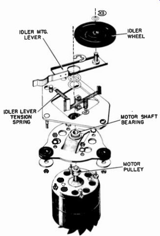
Fig. 4-10. Exploded View of Revere Model T100 Motor Drive Mechanism.
If the capstan does not operate, fuses blow, or coils are over heating, check first for mechanical overloading. With a rim-drive motor this can be done by spinning the capstan and the rotor shaft with the idler disengaged. Then test the idler for sticking. All three should turn easily and freely. If they do, the next step is to check the electrical circuit of the motor. Mechanical noise and speed troubles require a more detailed physical inspection of the entire motor and drive mechanism.
All parts, surfaces, and dimensions that can affect the speed are of a critical nature. Intermittent slippage of some part of the drive system or parts that are not absolutely concentric with their axes of rotation will cause wow.
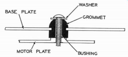
Fig. 4-11. A Vibration Mounting Between Motor Plate and Base Plate.
A motor will inherently transmit vibration to surrounding objects unless adequate provision is made to "float" it, so that it is not solidly mounted, cushioning its movement. Rubber vibration mountings or grommets, surrounding the bolts or bushings, are used to fasten the motor plate to the under side of the base plate of the motorboard as shown in Fig. 4-11. If the vibration mountings are under compression, they cannot accomplish their purpose. There should be a small gap between the rubber and the hold-down washer. With some motors a spacer is included which is placed over the bolt and inside the grommet, preventing any erroneous tightening of the bolt. It is also essential that the rubber is resilient. Grommets that have hardened, collapsed, or become oil-soaked should be replaced.
Lubrication of the self-aligning type rotor shaft bearings should seldom, if ever, be necessary. However, motor manufacturers' advice concerning this lubrication vary in details. Nevertheless, all manufacturers caution against over-lubrication and insist that any lubricant used must contain an oxidation inhibitor. It is also important that the viscosity remain nearly the same over a fairly wide temperature range. An oxidation inhibitor prevents the tendency of the oil to thicken, becoming gummy, or turning to a varnish under high temperature conditions or long exposure to air.
Do not use any light household oils to lubricate motor parts, since these may not contain an inhibitor to prevent gumming. This risk can be avoided by buying regular motor oil that is known to contain an inhibitor. SAE No. 10 motor oil of high quality generally is satisfactory.
Shaft bearings that are gummy from being lubricated with a non-inhibited oil will need to be cleaned with carbon tetrachloride before being re-lubricated. Apply only one or two drops of oil to the felt bearing washer, and after it has become saturated, wipe off thoroughly any excess oil that has reached other parts of the motor, giving special attention to the motor pulley and idler tire.
The air gap between the rotor and the stator is very narrow. To test for worn or misaligned bearings, check the shaft for play. See Fig. 4-12. If the shaft can be moved at right angles to its axis, the rotor will, when revolving, be scraping the internal circumference
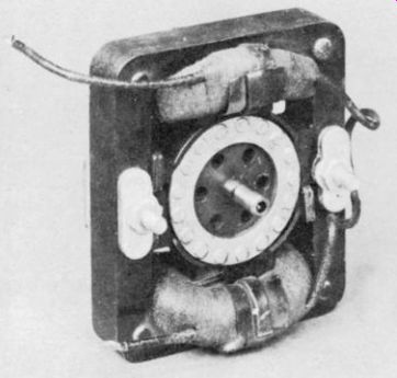
Fig. 4-12. To Test for a Misaligned Bearing, Check the Shaft for Play.
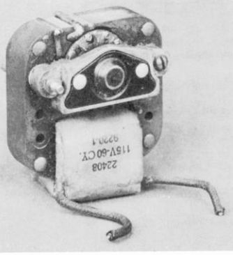
Fig. 4-13. A Typical Motor Using Sleeve-Type Bearings
of the stator laminations. Sometimes alignment of the sleeve-type bearings can be regained by tapping the bearing bracket. A typical motor using sleeve-type bearings is shown in Fig. 4-13. Tap the side of the gap that is narrowest with a light hammer, preferably a wooden or raw-hide mallet. If the fault is due to the bearings being worn to a considerable extent, the motor or its bearings should be replaced. An exploded view of a typical end bracket and bearing assembly is given in Fig. 4-14.
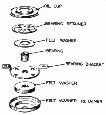
Fig. 4-1 4. Exploded View of a Typical End Bracket and Self-Aligning
Bearing Assembly.
Ball bearing motors are designed so that the bearings have a light press fit on the motor shaft and a sliding fit in the bearing housing. Adjusting the tightness of the case screws may be necessary with a ball-bearing motor before proper freeness is attained.
Worn or misaligned bearings, or a bent rotor shaft, will cause capstan speed variations by varying the friction of the motor pulley against the idler drive wheel. When the motor is running with the idler wheel removed, the appearance of the rotor shaft, viewed from the end of the motor pulley, should be circular and not a "wobbly" or elongated pattern.
Such parts of motors as laminations, shading rings, magnetic shunts, bearing brackets, and screws which hold the motor to its mounting plate, must be tightened securely to prevent buzzing. For this reason, the laminations are usually varnish impregnated and are tightly secured by rivets while being subject to a pressure of several tons.
Rivets that are loose should be tightened or driven out and replaced with new rivets or bolts. When tightening the bearing brackets, care should be taken that the alignment of the rotor and shaft are correct. Loose or broken shading rings may be soldered or welded and clinched. Broken shading rings will also cause a lowering of the speed under load. Buzzing shunts should be pressed out, bent slightly, and replaced. Due to the vital role of these bridges in motor performance, care should be taken to replace them in the same position they originally occupied. These bridges will sometimes be found with "off-center" holes or slots that affect motor operation.
If the capstan does not rotate and the motor is not stalled, all parts rotating freely, the electrical circuit should be investigated.
Continuity tests should be made from line input point through switch to motor coil. The resistance of the windings will probably be between 25 and 50 ohms. Opens external to the coil itself may be repaired. Connections between coils, on motors of more than one coil, must be kept in their original order. Incorrect connections will result in reversal of the fields which, with a two-pole, two-coil motor, would cause excessive current drain and no torque, and with a four-pole motor, would cause a great reduction of speed and torque.
Shorted turns in the coil will affect motor speed and can ordinarily be detected by the coil overheating and the unusually high current drain.
It is not advisable or economically practical to try to rewind burned-out coils or those that have shorted windings. Since most of these motors do not employ layer windings, a special type of winding machine is required. Repairs necessitated by mechanical wear and strain can often be made reliably and at less cost by replacement of the motor.
When selecting the range for an ammeter to be used in a motor circuit it should be kept in mind that the power factor of the motor is apt to be quite low. Therefore, generally, the amount of current calculated by using the voltage and wattage rating of the motor should be approximately doubled. Also, motor ratings are usually given for "running" condition; the starting power will be much higher. For the small skeleton-type motor a current range of approximately .3 to .8 amps should be expected if the motor is in good condition. It is recommended that initial measurements be made with an AC ammeter of 1 ampere full-scale. Because of the relatively low efficiency of these motors (approximately 30%) there is little difference in the power demand between the heavy-duty motors and the smaller ones.
In most units hum will result if the connection from chassis ground to a solder lug attached to the laminations by one of the mounting bolts is broken. An ohmmeter should be used to check that the winding is not grounded to the laminations. Grounded windings would, in most cases, result in fuse blowing. They also may cause hum in the output.
Not much can be done through design to improve the efficiency of either the shaded-pole induction motor or the synchronous motor. As far as operating cost is concerned, it is relatively unimportant that there is a waste of power in the motor because the total amount required is so small. It is of more importance that the inherent inefficiency results in the watt-loss being converted into heat. Design compromises necessitated by starting torque requirements, space limitations, choice of materials and manufacturing cost considerations tend to further reduce efficiency to such an extent that the operating temperature of these motors is generally almost as high as regard for safety will permit.
Underwriters' Laboratory specifications for motors in recorder applications permit a coil temperature, as measured by thermocouple, of 194° fahrenheit when the room ambient is 77° fahrenheit with the motor in normal operation in the unit, and with the maximum rated voltage and frequency applied. The temperature of the coil windings may rise to 221° fahrenheit when resulting from a heat source external to the coil. Temperatures should not exceed 347° fahrenheit under abnormal conditions such as locked rotors.
Shaded-pole motors are for alternating current use only, usually for 60-cycle frequency. Replacement motors for 50-cycle operation are available from most manufacturers. Consistent with the manufacturers' recommendation, conversion from 60 cycle to 50 cycle operation can sometimes be accomplished by changing the motor pulley to one of a larger diameter. This pulley must be supplied by the manufacturer of the recorder and the conversion is possible only if the laminations and coil have been designed for use on both frequencies.
It is possible to convert the recorder from 117- volt 60-cycle AC to 117- volt DC by the addition of a vibrator inverter. Several of these small power supplies are on the market for recorder use.
-------