In every recording medium, to obtain optimum recording results, the recording level or volume must be adjusted to avoid distortion.
Cause of Distortion
In magnetic recording, distortion is caused by the fact that if a given signal becomes progressively stronger and stronger, eventually the tape's magnetism will no longer increase. The tape is then said to be "overloaded." The overload point of a magnetic tape is also called saturation of the tape. One obviously wants to record considerably below tape saturation to avoid distortion. Fig. 5-1 shows the effect on a complex wave when recorded at too high a level.
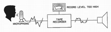
Fig. 5-1. When a Complex Wave Is Recorded of too High a Level, the Pecks
Will Overload the Tape and The Wave Itself Will Be Distorted on Playback.
Tape records symmetrically. That is, when the tape leaves the erase head and before it passes across the magnetic record head, it is essentially neutral or in a demagnetized condition. As a signal is recorded on the tape, the tape is magnetized first in a north-pole direction and then in a south-pole direction. Since magnetization occurs symmetrically, there is no even order harmonic distortion from the tape. However, when too strong a signal is applied to the tape and tape saturation is encountered, the peaks of the waveform are clipped. Serious third harmonic distortion results, as shown in Fig. 5-2.
The normal method followed in adjusting the recording level of the tape is to record so that volume peaks never exceed 3% third harmonic distortion. When we speak of peaks in recording music or voice, the wave form is very irregular. At times the amplitude will...
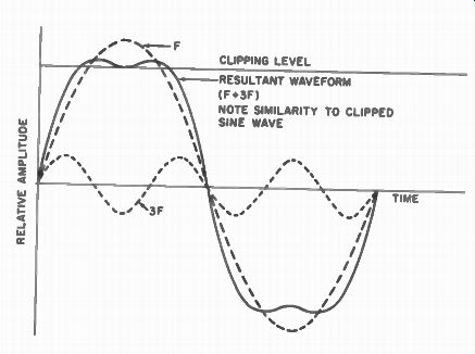
Fig. 5-2. If a Pure Tone (Sinusoidal Waveform) is Recorded at too High
a Level, the Peaks Will be Flattened or "Clipped". If We Add,
Point by Point, A Sine Wave of One Frequency (F) and a Sine Wave of Three
Times the Frequency of the Fundamental (3F), The Resultant Waveform is
Almost Identical to the Clipped Waveform Caused by Over-Recording.
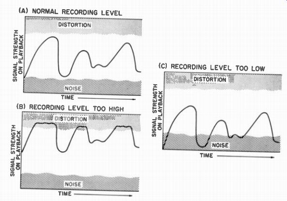
(A) NORMAL RECORDING LEVEL (B) RECORDING LEVEL TOO HIGH
Fig. 5-3. One Should Record at as High a Level as Possible Without Entering the Distortion Region; Otherwise, with a Weak Recording the Background Noise will be Excessive.
...be very weak. At other times it reaches very loud or electrically strong proportions as shown in Fig. 5-3A. When recording very strong passages, care must be exercised to avoid overloading the tape as illustrated in Fig. 5-3B. On the other hand, it is vital not to record with too low a level so that weak passages are swallowed up in noise during playback as in Fig. 5-3C. Therefore, it can clearly be seen that the recording level determines the signal-to-noise ratio and the distortion. The prime rule to follow is to record at as high a level as possible without entering into the tape's distortion region.
Present Day Recording Volume Indicators
To avoid the pitfall of entering a tape's distortion region, some type of volume indicator is required to permit adjustment of the recording volume or signal amplitude as it is being fed to the tape.
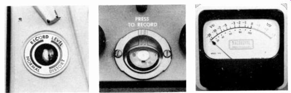
Fig. 5-4. Present Day Tape Recorders Employ Three Types of Recording
Indicators: (A) Neon -A Peak Indicating Device (B) Electron Eye-Also a
Peak Indicating Device (C) V-U Meter- An Average Indicating Device.
Over the years a number of different types of recording indicators have been tried. On present-day tape recorders there are three main types: the neon, a peak indicating device; the electron eye, again a peak indicating device; and the VU meter or an average indicating device. A photo of these three types of recording indicators is given in Fig. 5-4.
The Neon Volume Indicator
The neon volume indicator is the most common type of volume indicator used in home-type recorders. A neon bulb is used which will not light until its applied voltage reaches a certain point. Then, suddenly, it will ignite and glow. Thus, it can be used as a peak or volume indicator.
A peak is reached whenever the applied voltage exceeds the ignition or firing point of the neon bulb, causing it to light. Consequently, in the less expensive recorders using one neon bulb, the volume-level indicator will be adjusted so that when the signal reaches approximately 3% distortion (or generally a little less to provide a safety margin), it will light.
When recording, it is necessary to adjust the volume so that the bulb will only occasionally light. This means that during most recording the volume is adjusted well below the distortion point, with only the peaks entering the distortion region.
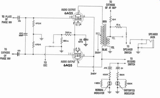
Fig. 5-5. A Typical Neon Bulb Volume-Indicating Circuit- Shown is the
TDC Model 130.
A further refinement of the neon bulb indicator is accomplished by using two neon bulbs. One neon bulb is set to fire when the recording signal reaches, say, 3% harmonic distortion, whereas the other bulb is set to fire at a point somewhat under 1%. Consequently, the latter bulb serves as a lower level volume indicator and the first bulb serves as a peak volume indicator. During recording one neon bulb is lit most of the time, indicating a normal recording level. When the second neon bulb fires, the peaks are entering the distortion region. The two-bulb system is a basic improvement and is now incorporated on several of the newer home-type recorders. A partial schematic of a typical recorder using two neon bulbs is given in Fig. 5-5.
The Electron-Eye Volume Indicator
The second volume-indicating device is the electron-eye tube. This tube has an electron beam that strikes a fluorescent surface, causing an iris-shaped image to appear. In the peak or fully modulated position, the electron-eye tube is as shown in Fig. 5-6. During recording, the two halves should be vibrating so that they never overlap in the manner shown in Fig. 5-7.
The electron-eye has an advantage over the neon bulb in that a visual indication of the recording level is provided, even during weak signals. By contrast, in the one-bulb neon system, weak signals are not indicated, making it impossible to judge their amplitude.
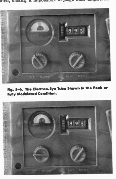
Fig. 5-6. The Electron-Eye Tube Shown In the Peak or Fully Modulated
Condition.
Fig. 5-7. During Recording, the Two Halves of the Electron-Eye Tube Should be Vibrating So That They Never Overlap in the Manner Shown Above.
Both the neon bulb and the electron-eye tube suffer from several disadvantages. The neon bulb will respond only to a given voltage, then will suddenly light, serving only as a peak indicating device. The electron-eye tube responds linearly to the applied voltage. That is, it does not follow our hearing characteristics which are logarithmic. In effect, this means that weak signals are completely lost or are barely indicated on the electron-eye. Relatively strong signals are required to get a volume indication.
To avoid these disadvantages, giving an exact logarithmic indication of both weak and strong signals, a third device is used on practically all professional recording systems. It is the VU meter.
The VU Meter
The VU meter is an electrical meter responding in a logarithmic manner to an applied voltage or current. The VU meter is also an average indicating device. A certain inertia is built into the needle so that on a varying signal input, it will respond in a damped manner which gives an average indication of the signal level.
All VU meters are carefully built to have the same damping factor . Consequently, a recordist accustomed to reading one particular VU meter may look at a VU meter on any other recorder and judge the correct reading volume.
Since "0" level on a VU meter is an average and is considerably below the peak amplitude of the recording signal, it is necessary to locate the "0" level somewhat below the distorted region of the tape. Generally, "0" level on the VU meter, or 0 - VU, is 8 db below 3% harmonic distortion. This 8 db margin gives ample protection for loud passages or loud peaks that are too rapid to show on the meter.
Tests for Proper Adjustment
A series of fairly simple tests will quickly determine whether or not the volume indicating device of a recorder is properly adjusted and is correctly functioning.
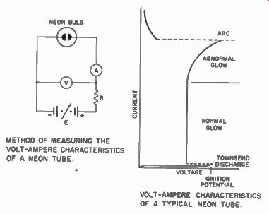
Fig. 5-8. Voltage Verses Current Curve For a Typical Neon Bulb. METHOD
OF MEASURING THE VOLT-AMPERE CHARACTERISTICS OF A NEON TUBE. VOLT-AMPERE CHARACTERISTICS
OF A TYPICAL NEON TUBE.
The neon bulb indicator is generally connected across the output of the recording amplifier, just before the signal is fed into the recording head. Its reference level is established by applying a current of DC voltage to it. For example, if the bulb is intended to fire whenever the signal's amplitude goes beyond 5 volts and the ignition point or light voltage required to light the tube is 60 volts, 55 volts of direct current should be applied to the tube. Then the signal will be superimposed on the direct current so that whenever the signal amplitude reached 5 volts the tube will fire. A voltage versus current curve for a typical neon bulb is given in Fig. 5-8.
All adjustments are generally fixed on most recorders. The resistances which determine the applied DC voltage are generally fixed values so that the neon bulb will light at a predetermined signal level. However, it can be checked with a distortion-measuring device. The neon bulb should fire at somewhere between 1% and 3% third harmonic distortion.

Fig. 5-9. Circuit Employing an Electron-Eye Tube as the Volume Indicator-
Shown is The Webster-Chicago Model 2010.
Slightly more complicated than the neon-bulb indicator, the electron-eye tube gives the voltage instantaneously as the audio signal fluctuates. Since the audio signal fluctuates so rapidly, one would normally expect to see just a blur. However, in order to make readings possible, generally a capacitor network is used to remove rapid fluctuations and pass only gradual voltage changes, tending to give an averaged value of output somewhat similar to a VU's damping effect. A partial schematic showing a typical electron-eye circuit is given in Fig. 5-9. However, the fact still remains that the electron-eye indicator is a linear function of applied voltage, whereas in the VU meter it is a logarithmic function.
The most common cause of trouble in a VU meter is that the needle becomes bent or the movement is actually burned out or damaged. Without exception, if the VU is damaged it should be sent to the factory for repair or replacement.
-------