A jack of three trades, the bias oscillator serves the all- important function of making linear and distortion-free low-noise recordings while erasing the tape. But unlike the proverbial jack of all trades who was master at none, the bias oscillator performs all three functions admirably.
Two General Bias Methods
There are two general bias methods employed in magnetic recording. One is direct-current bias; the other is alternating-current bias.
The early wire and steel band magnetic recorders of Valdemar Poulsen used direct-current bias. One of the chief limitations of the Poulsen magnetic recorder was the use of direct-current bias, which prevented the recorders from finding wide public acceptance. Despite Poulsen's brilliant design, the use of DC bias inevitably resulted in distorted recordings with considerable hiss and noise.
However, with the introduction of alternating-current bias in the middle twenties, magnetic recordings of high quality became possible for the first time. This discovery of W. L. Carlson and G. W. Carpenter of the U. S. Naval Research Laboratory opened up an entirely new vista for magnetic recording.
The purpose of alternating bias is to produce a linear recording characteristic. This means that if the signal is doubled, one will obtain twice the output from the tape during playback. If the recording characteristics were non-linear, and the signal were doubled, one might obtain either more or less than twice the output.
In the magnetic recording process, the recording characteristics must be linear. In magnetizing any iron or steel substance, a hysteresis curve is encountered. A typical hysteresis curve is shown in Fig. 6-1.
When an increasing magnetizing force is applied to the tape, and then removed, the tape will have a certain remanent flux. In magnetic recording, the remanent flux is the actual magnetic field that creates the signal during playback. Ideally, if the tape were ...
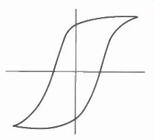
Fig. 6-1. Hysteresis Curve
of Typical Magnetic Re cording Material. The Horizontal Axes Indicates
the Strength of the Recording Signal. The Vertical Axis Gives the
Amount of Magnetic Field Left in the Tape.
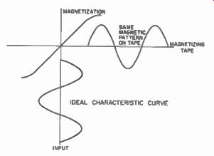
Fig. 6-2. Ideal Recording Characteristic- If We Had an Ideal Magnetic
Recording Medium a Given Amount of Recording Signal Would Produce a Magnetic
Field Exactly Proportional to It on the Tape.
...recorded linearly for a given magnetic force recording signal, an equal remanent flux would be obtained. (See Fig. 6-2.) If we were to double the recording signal, we would, theoretically, in turn double the remanent flux. However, from the curve shown in Fig. 6-3 it can be seen that the magnetic field on the tape is no longer proportional to the recording signal.
Theory of DC Bias
The first serious bias attempt was the DC bias method discovered and incorporated by Poulsen in his Telegraphone recorder. It is interesting to note how DC bias operated. In DC bias, the tape was completely magnetized by a permanent magnet, generally serving also as the tape eraser. Thus, when the tape met the recording head, it was in a completely magnetized condition. All the magnets were ...
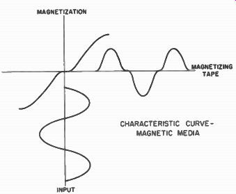
Fig. 6-3. Actual
Magnetic Recording Characteristic With No Bias- Notice the Magnetic
Field on the Tape is No Longer Proportional to the Recording Signal.
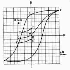
Fig. 6-4. DC Record Curve.
...oriented in one direction. Then, as a recording signal was applied, the recording signal surved to demagnetize the tape. The amount of demagnetization was determined by the strength of the signal. At the same time a certain amount of direct current was applied simultaneously to the head. The direct current was used to place the operating signal within a more or less linear region of the hysteresis curve.
When recording is to be accomplished by means of DC bias, the procedure involved is the following: The recording medium is, first of all, magnetically saturated in a certain direction with a DC erase head, as indicated by OAB in Fig. 6-4. Then in the record head, the function of the DC bias is to bring the medium to a point such as D. For no signal, on leaving the record head, the tape will be in the magnetized state D' . In the presence of a signal, the tape coming from the state B may reach the points DCE etc., and hence, have a recorded signal on it corresponding to C, D', E', and etc.
When employing DC bias very little of the potential magnetization of the tape was used, resulting in noisy recordings with a high hiss level. Unless elaborate precautions were taken to adjust the DC or permanent magnetic fields accurately, a large amount of distortion would also result.
The defects of the DC bias method led to the development of the alternating-current bias. AC bias is now used in all magnetic recording applications for audio work.
Frequency of the Bias Supply
It is obvious that an alternating current is needed to supply an AC bias system. The bias current is generally many times the strength of the recording current. Consequently, far more bias is needed in the record head than audio signal. The amount of bias may be as much as 10 times the strength of the audio signal although, generally, it is only several times as great.
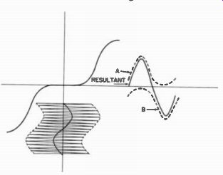
Fig. 6-5. Magnetic Characteristics With Bias. When a Bias Frequency is
Added to the Audio Signal the Resultant Magnetic Field is Made Proportional
to the Recording Signal.
Fig. 6-5 illustrates the action of AC biasing. A field which is a mixture of the AC bias and an audio signal is shown applied to the residual flux-density curve. In Fig. 6-5 the projection of the positive peaks on the residual flux curve at each instant of the audio signal produces curve A. The projection of the negative peaks forms curve B. The addition of curves A and B represents the effective flux signal that will be reproduced. Although some distortion is present in the resultant curve, it is a great improvement over reproduction without bias.
In order not to be heard, the bias must be at a higher frequency than the audio signal. The frequency of the bias, while not critical, must be well above a certain value. This point is generally five times the highest audio frequency to be reproduced. This is necessary in order to avoid beats or whistles in the audio frequencies being heard during the recording process. The harmonics of the audio signal that beat with the bias frequency cause a whistle or heterodyne.
When a whistle develops, two alternating currents of different frequencies are mixed together in a slightly non-linear recording system. For example, if an audio frequency of 10,000 cycles were recorded and a bias frequency of 35,000 cycles was used, the third harmonic of the audio frequency would be 30,000 cycles. Since the bias frequency was 35,000 cycles, a 5,000-cycle note intermittent whistle would be heard in the recording.
Generally the second and third harmonic components of an audio signal are the strongest. The fifth harmonic component is relatively weak, giving little trouble. Therefore, if the highest audio frequency to be recorded is 15,000 cycles, the bias frequency should be at least 60,000 cycles. Or, again, if the highest audio frequency to be recorded is, say, 7,500 cycles, the bias frequency should be at least 30,000 cycles. The trend of recent recorder design is toward higher and higher bias frequencies in order to avoid any chance of heterodyne.
In present-day professional recorder design, bias frequencies generally are in the region of 80 kc. Home recorders use bias frequencies in the region of 40 to 50 kc. A few home recorders still operate at bias frequencies as low as 30 kc.
Erasure
There is no limitation on how high a bias frequency can be used except for those limitations imposed by the bias and erase currents.
Since the bias supply serves as a supersonic oscillator, it forms a handy source of power for the erase head for use during erasure of the tape. The erase head requires considerable power to completely erase the tape. With the trend toward higher and higher bias frequencies, it is becoming increasingly difficult to apply sizable amounts of power to an erase head. Therefore, it is desirable from a design standpoint to use a relatively low bias frequency in order to have sufficient power to operate the erase. However , sound-wise it is best to have as high an audio frequency as practical.
Bias Strength
Another crucial aspect of bias is its strength. From the curve shown in Fig. 6-6, it can be seen that as the bias strength is increased, with more and more bias current applied to the record head, the low frequency signal output from the head will also become progressively stronger but will reach a peak, and then slowly taper off. In order to determine the proper bias strength or bias amplitude current to be fed to the recording head, it is necessary to know some of the properties of bias.
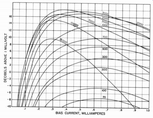
Fig. 6-6. Notice the Above Graph Shows the Self-Erasure Effect of Bias
in High Frequencies, As the Bias is Increased, the High Frequency Response
is Attenuated.
The point at which the bias current gives the greatest amount of output with a low frequency audio signal is known as peak bias. This term is somewhat misleading since peak bias would seem to indicate a stronger bias. However, the word peak refers only to the strength of the audio signal during playback of the tape.
Most machines operate in an over-bias condition. Over bias means that the bias is stronger than that required to obtain peak output which, in turn, reduces the output. If the bias is so strong that it will reduce the output by 2 db, the recorder is referred to as being 2 db over-biased.
If the bias is less than that required to give peak audio output, not only will the output suffer, but the signal -to -noise ratio will also be adversely affected, and severe distortion, together with poor uniformity, will set in (see Fig. 6-7). Even the nodules and imperfections on the tape surface itself will be accentuated with low bias.
However, the main disadvantage of low bias is the high distortion and low-signal output encountered.
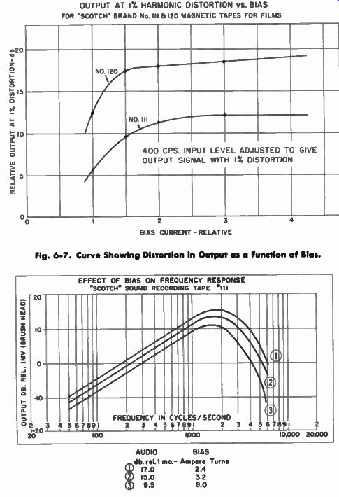
OUTPUT AT 1% HARMONIC DISTORTION VS. BIAS
Fig. 6-7. Curve Showing Distortion In Output os o Function of Bios.
Fig. 6-8. Curve Showing the Effect of Bios on the Output for a Constant Input Signal of Low Frequency.
In the case of over-bias, the distortion is generally somewhat reduced beyond the point of peak bias. In fact, as the bias is increased the distortion becomes progressively less. However, the signal output begins to drop, though slowly, causing a reduction in the signal -to-noise ratio.
The main disadvantage of over biasing is the marked loss of high frequencies (see Fig. 6-8). As the bias strength is increased, the bias actually serves as an erasing field for the tape, erasing the weaker high-frequency signals on the tape. Since high-frequency signals are more easily erased than low frequencies, the bias is actually erasing the high-frequency audio signals on the tape. By increasing the bias by one or two db over-bias, the high frequencies will begin to be attenuated, although they are not severely affected with this amount of over -bias. On an oscilloscope the surface uniformity will look better, and the distortion characteristics are generally improved.
Therefore, in summary, if the bias is too low, distortion will result. If the bias is too high, a loss of high frequencies will occur. The decision, then, is this: Should a recorder be operated at peak bias or slightly over peak bias? Operation at peak bias generally makes possible the best high frequency response since it is in a very ...
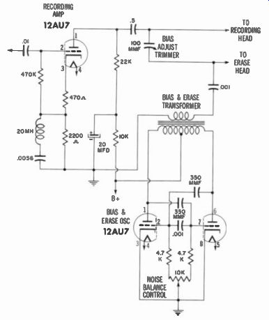
Fig. 6-9. Circuit of Ampex Model 600 Recorder Showing Variable Capacitor
In Series With Head Circuit Providing a Means to Adjust Bias Current.
... good region as far as distortion is concerned. If distortion is very low, peak bias generally will also give the best signal-to-noise ratio. The only disadvantage of peak bias is that the surface irregularities of magnetic tape have a tendency to be somewhat more pronounced. However, thanks to recent improvements in magnetic tape construction techniques, nodules and other surface irregularities are relatively unimportant as far as audio applications are concerned.
Adjustable and Fixed Bias
The philosophy of most machine manufacturers, if they do not incorporate an adjustable bias in their recorder, is to build machines fixed at somewhat over-bias. This technique, due to variation in production components, will allow a few machines to be biased at peak bias while a few machines will also be substantially over -biased. However, most machines will fall in a region of approximately 2 db over-bias. In general, the performance of most machines can be improved if an adjustable bias is incorporated in their design. Most professional recorders have an adjustable bias. The adjustable bias circuit used in the Ampex model 600 is shown in Fig. 6-9. Ampex requires operation at peak bias while several of the other professional manufacturers specify operation at 2 db over-bias. The trend in later years has definitely been toward the use of peak bias for all professional recording equipment.
Bias-Oscillator Design
The bias oscillator itself is generally a simple L-C circuit with either a tuned plate or a tuned-grid class-C oscillator employing a triode tube. In some of the professional recorders, dual triodes are used in push-pull, as shown in Fig. 6-10, in an effort to reduce second harmonic distortion.
A common cause of distortion arises from an improper bias waveform. In the bias signal wave, if one side of the wave has greater amplitude than the other, the tape will become magnetized and, as discussed earlier, second harmonic distortion will be introduced. Therefore, it is extremely important that the bias supply have good sinusoidal waveform. In an effort to do this, the professional manufacturer almost invariably will use push-pull oscillator tubes to eliminate any second harmonic component in the bias waveform that could possibly introduce second harmonic distortion in the tape recording itself.
While very little bias current is needed for the recording process, the bias oscillator is also called on to supply considerable current for the erase head. The current required for erasure is often as much as ten to thirty times as high as the current required for the recording process. Therefore, an oscillator must have substantial power to deliver the current for erasure. Most erase heads need almost 4 watts of power to do a complete job of erasure. This means that the oscillator must be capable of supplying up to 4
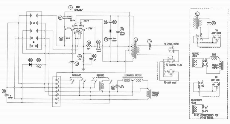
Fig. 6-10. In the Magnecord Model PT6 A Push-Pull Bias Oscillator Provides
a Bias Current Free of Second Harmonic Distortion.
... watts of power at a high frequency. In general, this is the frequency limitation imposed on the bias oscillator.
It is desirable, as we have seen earlier, to have the frequency as high as possible to avoid beats. However, it is difficult to design an oscillator to deliver considerable power at high frequencies without involving added expense. Therefore, the design of the bias oscillator represents a compromise between sufficient output for tape erasure and high enough frequency to avoid heterodynes in the recording signal.
The lower -priced home-type recorders generally use single tube class-C oscillators which, for most purposes, serve quite well. A few recorders use a tube operating as a low-power oscillator tube and use the output stage of the amplifier to amplify both the audio signal and the bias signal. This performs quite well if the output stage of the amplifier introduces no distortion in either the audio signal or the bias waveform. Generally, it is considered better practice to feed directly into the head.
Bias Feed
There are two types of bias feed to the record and erase head. One is series feed, shown schematically in Fig. 6-11, very prevalent ...
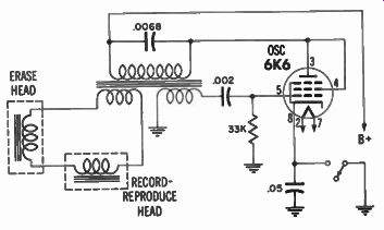
Fig. 6-11.
Method of Applying Bios to Record Head by Means of a Series Circuit.
... in early recorder designs. The second is shunt feed, most commonly known today. See Fig. 6-12. The bias frequency is actually added to the audio frequency. The audio frequency does not modulate the bias frequency as in the case of AM (amplitude modulated) radio waves. But rather a waveform is produced such as those shown in Fig. 6-13.
The series feed has the disadvantage that the bias is not easily controllable. If One adjusts the bias on the record head, either the erase current will be lowered or if the bias is shunted through the record head, a load will be placed on the audio signal. Therefore, the series feed method does not lend itself toward an adjustable bias control which has been the reason why this method of feed has been generally abandoned.
In shunt feed, it is possible to regulate both the erase current and the bias current. The most common type of bias feed in use today, shunt feed, requires a simpler head design and permits the use of high-impedance heads.
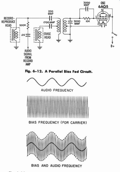
Fig. 6-12. A Parallel Bias Fed Circuit. AUDIO FREQUENCY BIAS FREQUENCY
(FOR CARRIER) BIAS AND AUDIO FREQUENCY
Fig. 6-13. Waveform Obtained When Audio and Bias Frequencies are Mixed (Added) Before Going to the Recording Head.
Trouble Hunting
If a recorder has severe distortion in the audio signal, one of the first places to look is in the bias oscillator. Is the bias oscillator tube functioning? Is it functioning well? If the oscillator tube becomes at all weak, both the erase will suffer and the bias will, of course, be reduced while the signal will become distorted.
If the tube is not faulty and the signal is still found to be weak, look for faulty components. The bias waveform should be checked with an oscilloscope to obtain a rough approximation of its shape. It can be easily seen if the output is a good sinusoidal wave. If the wave form is not sinusoidal, definitely something is wrong in the oscillator and should be corrected to obtain good, low distortion recording results.
-------