If a constant amplitude signal were fed into a magnetic recording head and then played back, one would expect to obtain a flat or uniform amplitude over the frequency band. In reality, the resulting curve is far from uniform and flat.
This can be seen by examining the graph in Fig. 7-1. It will be noted that even though a constant amplitude input was fed to the tape, the output curve is insufficient in both low and high frequencies. The reason for this is that in magnetic recording the voltage induced in the playback head is proportional not only to the strength of the magnetic fields recorded on the tape but also to their rate of change or frequency.
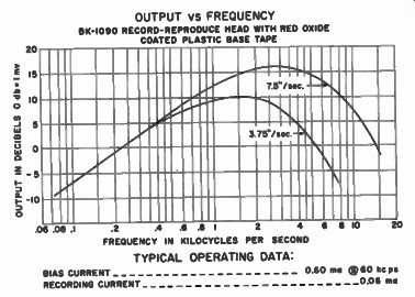
Fig. 7-1. Output From a Typical Magnetic Reproduce Head When Playing
a Tape Recorded With a Constant Current for All Frequencies.
Since a high-frequency signal has many more magnets and its field is changing faster than a low-frequency signal, it will produce a greater amplitude. In practice, a 200-cycle signal will give exactly
twice the output voltage of a 100-cycle signal. That is, if we double the frequency, we double the output in magnetic recording.
By a simple computation, we can see that by doubling the voltage, a 6 db increase in amplitude is obtained. Therefore, the magnetic recording characteristics rise at a rate of 6 db per octave. If the frequency is raised one octave or doubles, the output increases 6db.
This accounts for the falling off at the low frequencies. Around 1,000 to 2,000 cycles, the output reaches a peak and then tapers off at higher frequencies. This tapering off is due to losses in the head due to gap effects and the magnetic head core structure.
Need for Equalization
Losses at both the low and high frequencies means that to obtain good frequency response on a magnetic recorder, one must equalize or compensate for these losses at both the low and high end.
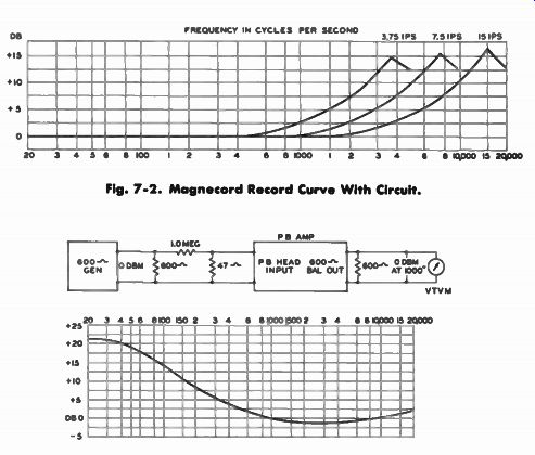
(top) Fig. 7-2. Magnecord Record Curve With Circuit. (above) Fig. 7-3.
Magnecord playback.
The equalization may be accomplished by a variety of methods. However, in professional recording equipment, generally the tape is recorded with a boost in the high frequencies as shown in Fig. 7-2 and played back with an amplifier that boosts the low frequencies as in Fig. 7-3. Thus, the low frequency loss is corrected in playback and high frequency loss is corrected in recording.
The reason for equalizing in this manner is to obtain the best possible signal-to-noise ratio without entering the distortion range. To obtain the best signal-to-noise ratio, it is desirable to put as strong a signal as possible on the tape regardless of frequency, without overloading at any frequency. This means that if the tape has a strong signal recorded on it, only a minimum of amplification will be required during playback.
The noise level in magnetic recording is generally due to tube hiss, microphonics, and hum created in the playback amplifier and does not result from the tape itself. In theory, tape has no surface noise, but has only modulation noise.
High-Frequency Equalization
If we should record with a "flat" record amplifier (gain constant at all frequencies), the high frequencies would be very weak when reproduced from the tape due to the losses at high frequencies, and we would need excessive gain to reproduce them at their normal level. However, if we should boost the high frequencies during the recording process, it would compensate for the losses and it would still be impossible to overload the tape. This is because sound waves as generated by the human voice or musical instruments have less strength at high frequencies and the tape overloads at essentially the same amplitude regardless of frequencies. Therefore, high-frequency equalization can be accomplished during the record process without entering into the distortion range.
Low-Frequency Equalization
Low-frequency equalization is another matter. The power centered in vocal and musical sound waves is located in the low frequency range. Consequently, low-frequency equalization must be accomplished during playback to avoid overloading or distorting the tape.
However, in less expensive recorders, low-frequency equalization is often accomplished both in the record and playback process.
While this does not give theoretically the best signal-to-noise ratio, in practice this method yields the best results on lower-priced machines. The reason for this is that in small, inexpensive home-type recorders components such as the motor, power transformer, and amplifier produce quite large hum fields. Without expensive shielding, the magnetic reproduce head tends to pick up from these fields an excessive amount of hum.
If the full low-frequency equalization is accomplished in playback, the hum will be greatly amplified. However, if part of the low-frequency equalization is accomplished during the record process, less amplification will be needed at low frequencies during playback, thereby helping eliminate the hum.
Still other recorders, in an effort to simplify the record-playback switch functions, use only one equalization circuit for both record and playback. Therefore, both low frequencies and high frequencies are equalized in recording and playback.
The method of equalization used in the record process is known as pre-equalization. The equalization used in the playback process is referred to as post-equalization.
Differences in Equalization
Due to differences in equalization between recorder manufacturers, tapes recorded on one machine will not necessarily sound good on another machine. For example, consider a tape recorded on a professional recorder with no low frequency pre-equalization but using the full high frequency pre-equalization. The recording will sound unduly sharp and harsh with shrill highs and very little bass when played on a home-type recorder designed to have both low-and high-frequency equalization take place in the record and playback process.
Equalization for Dual-Speed Recorders
From the graph, Fig. 7-4, it can be seen that if the tape speed is doubled, the region of peak output is raised one octave or 6 db. When designing an equalization system for a dual-speed recorder, compensation must be made for the 6 db per octave loss at the low...
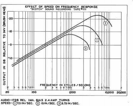
Fig. 7-4. Graph Showing the Effect of Speed on Frequency Response.
...frequencies and for magnetic head gap and core losses at the high frequencies. In dual-speed recorders, to obtain maximum performance it is imperative that an equalizer be designed for each speed. See Fig. 7-5.
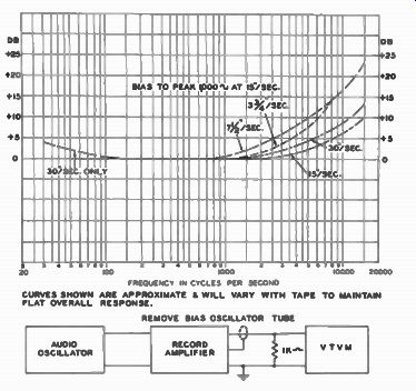
CURVES SHOWN ARE APPROXIMATE A WILL VARY WITH TAPE TO MAINTAIN ELAT OVERALL
RESPONSE. REMOVE BIAS OSCILLATOR TUBE
Fig. 7-5. Ampex Record-Amplifier Response.
On dual- speed professional machines, to accomplish peak performance, two separate equalizer networks are provided. Only the pre-equalization is changed in several professional recorders. The post-equalization or low-frequency equalization is the same for both 7 1/2 and 15- ips speeds. See Fig. 7-6. By changing only the high-frequency equalization, flat response is obtained at both speeds. In other dual-speed professional recorders both the high-and low- frequency equalization is changed to compensate for the change in speed.
In many home-type, dual-speed recorders, the amplifier circuits embody only one equalization circuit. This circuit may be designed in three ways: First, the equalization circuit may provide for optimum results at one speed only. In the case of most home recorders which operate at both 3 3/4 and 7 1/2 ips, the equalization circuit is designed for the higher speed or 7 1/2 ips. This means that at 7 1/2 ips, optimum performance is obtained from the machine.
However, when the speed is switched to 3 3/4 ips, not only is response lost through the decrease in speed but far from optimum results are obtained since the equalization circuit is not designed for the 3 3/4 ips speed. Consequently, when a tape is played at 3 3/4 ips on an equalization circuit designed to compensate for losses at 7 1/2 ips, the results can not help but be disappointing.
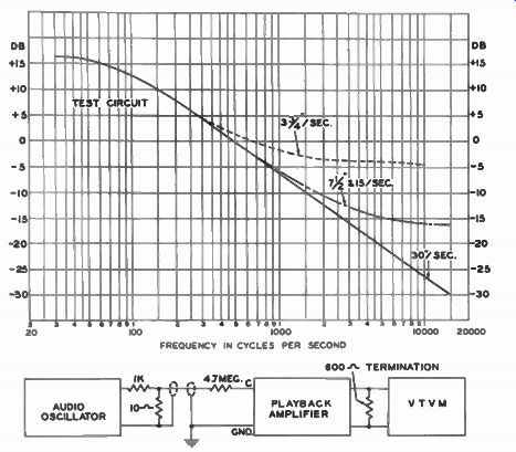
Fig. 7-6. Ampex Playback-Amplifier Response.
The second approach sometimes used in dual speed home-type recorder equalization circuits is to provide equalization for a non-existant intermediate speed. As an example, the equalization circuit may give optimum results at a speed of 5 ips. Therefore, when a machine is operating at either 3 3/4 or 7 1/2 ips, the results are naturally not as good as could be expected. True, the 7 1/2-ips speed will give better results than at 3 3/4 ips. However, neither speed will be entirely satisfactory. A frank compromise, this type of equalization circuit is designed to improve the 3 3/4-ips response while sacrificing some of the advantages obtained with a 7 1/2-ips speed response.
A third method of equalization of dual speed home-type recorders is finding increasing favor. This type of equalization recognizes the limitations in a short-cut, compromise approach and, instead, employs two different equalization circuits. See Fig. 7-7.
Those recorders that use two separate equalization circuits generally switch between the circuits with the same knob that controls the speed. For example, when switching to 7 1/2 ips, the equalization is automatically adjusted for that speed.
When purchasing a dual-speed machine, it is important to check the type of equalization circuits used and the method of switching, if any. There is little doubt that if optimum performance is expected from a recorder, the machine must change equalization for each speed.
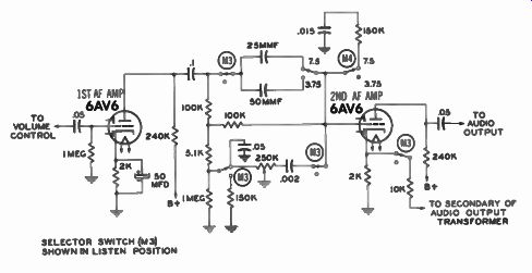
Fig. 7-7. Playback Equalization Circuit used in Ekotape Recorder.
Standardization of Playback Equalization
The National Association of Radio and Television Broadcasters has already adopted a standard professional playback equalization characteristic curve. Tapes are then to be recorded in such a manner that when played back with the standard playback characteristic, the output will be essentially flat.
However, in the home recorder field no such standardization yet exists. The lack of standardization represents a sizable roadblock in the path of the fast growing pre-recorded tape industry. In fact, even among professional recording machines, few follow the NARTB standard. However, in most professional machines the equalizations are sufficiently close that good results are obtained when tapes are recorded on one machine and played on another.
A standard is definitely needed among home recorder manufacturers. Up to the present time, each manufacturer has gone his own way in developing the equalization circuit that is best suited to his individual machine.
The Magnetic Recording Industry Association has formed an aggressive standardization committee to work out equalization circuits among all American recorder manufacturers early in the industry's growth. In addition, those foreign tape recorder manufacturers interested in importing their machines into the American market have also been invited to participate.
If tape is to compete on an even basis with present-day discs for the broad home-music market, standard playback curves must be established on home-type recorders so that pre-recorded music on tape will sound equally good on all machines. It is obviously an economic impossibility to expect dealers to stock a line of pre-recorded tapes, specially equalized for each of the major home-type recorders.
-------