The signal from the microphone is extremely weak, at the most only a few millivolts. Therefore, during recording an amplifier is needed to raise the feeble signal from the microphone to a relatively high level before feeding into the magnetic head. Adding still further complication during playback, the signal obtained from the magnetic reproduce head is also very weak, at the most approximately 8 millivolts. Again, an amplifier with very high gain is required to raise the signal strength sufficiently to drive a loudspeaker.
Because of the weak signal from both the microphone and magnetic reproduce head, it is easy to see that the record and playback amplifiers play a crucial role in the tape recording process. Both amplifiers operate from the same basic principles and have the same limitations. The only difference between the record and playback amplifier lies in the amount of gain required and the type of equalization used, a discussion of which is covered in another section.
Amplifier Characteristics
As the name implies, an amplifier is constructed to amplify or build a weak signal into a strong one. That is, the amplifier takes a very weak electrical signal, generally an electrical voltage, whether produced by a microphone or the signal from the magnetic reproduce head in the playback process, and raises this voltage many thousands of times. The signal is subsequently converted into current which is, in turn, used to drive a loudspeaker.
The amplifying process or the amount of amplification is technically known as the gain of the amplifier. There are two types of gain: voltage gain and power gain. Supplying voltage gain is the principal function of both the record and playback amplifiers, except for the output stage in the playback amplifier where voltage is converted to power.
To obtain gain a vacuum tube is employed. The vacuum tube, similar in function to a valve, enables a relatively weak voltage to control a large current or voltage. If the gain from one tube is insufficient, the tubes can be cascaded. In cascading, the output from the first tube is fed into a second, the output from the second is fed into a third. Then if each tube amplified, say, 10 times, two tubes would amplify 100 times, and three tubes 1,000 times.
In tape recorder applications, generally the gain of the first stage, which can be either a single pentode or a dual cascade triode may be several hundred. The following stage usually has a gain of between 10 and 60. So, therefore, in the first two stages of tubes in the cascade chain, there may be a gain of well over 2 or 3 thousand The gain of the amplifier is determined by three factors. First, the type of tube; second, the values of the circuit components -- and third, the mode of operation of the tube.
Type of Tube Required
In the early stages of a tape recorder's record-playback amplifier, a very high amplification is necessary to raise the weak signal to a satisfactory level while introducing as small an amount of noise as possible. In order to accomplish this objective, it is desirable to amplify the weak signal as rapidly as possible and then to amplify a relatively strong signal in the subsequent stages.
The pentode-type tube has an amplification of from 100 to 300 times. In this respect it is very desirable since it has high gain. However, it suffers from being more noisy than the triode" and introduces somewhat more distortion, although distortion is not a big problem in the early amplifier stages. A triode, while it has less gain, has far less noise and substantially less distortion. However, to duplicate the gain of the pentode, two triodes are necessary. The total results are often very similar, regardless whether amplification is obtained with two triodes or with one pentode. The number of circuit components is very nearly the same.
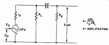
Fig. 8-1. Electrical Equivalent of a Triode Amplifier Stage and the Mathematical
Equivalent Showing its Amplification at Mid Frequencies.
Recent developments have led to the adoption of low noise tubes.Several excellent pentodes are now available, and the trend in recorder manufacture seems to be toward tubes like the 5879, which give a high amplification with little noise.
The amplification at mid-frequencies maybe easily determined by the following formula:
A = gm = R1 / r_p + R1
…where
gm = amplification factor of the tube
r_p = plate resistance of the tube
R1 = the load resistance, and the grid resistance of the following stage, in parallel. That is:
R1=
The vacuum tube, whether it be pentode or triode, can be represented as a generator whose output is the grid signal or the input voltage to the grid of the tube, times the amplification factor of the tube. In series with this generator is the plate resistance inherent in the tube. See Fig. 8-1.
By knowing these values, the circuit can be designed to give the desired gain while still possessing satisfactory frequency response.
Signal-To-Noise Ratio
It is obvious that the amplifier, while providing gain, should introduce as little noise as possible. In magnetic recording this is especially crucial because the signal -to-noise ratio of a tape recorder is primarily limited by the playback amplifier.
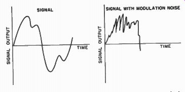
SIGNAL WITH MODULATION NOISE
Fig. 8-2. The Effect of Modulation Noise on a Recorded Signal.
Signal-to-noise ratio, simply stated, is the maximum signal obtainable from the amplifier before distortion sets in compared to the noise inherent in the system. In tape recording, the medium of magnetic tape introduces no surface noise. That is, if there is no signal recorded on the tape and, providing the tape is completely demagnetized, the tape will be completely noise free.
True, when the tape has a signal, as shown In Fig. 8-2, the output will vary and this is called modulation noise.
However, in determining the signal -to-noise ratio of the system, the maximum signal from the playback amplifier, generally 3% distortion, is compared to the completely erased tape. Since the tape, when completely erased will give no noise, the only noise present in the system is from the playback amplifier. Therefore, the signal-to- noise ratio of tape recorders is determined by the playback amplifier.
Noise-Reduction Techniques
Great care is taken in tape recorder design to reduce the noise inherent in the input stage of the amplifier. The reason why particular care is devoted to the input stage is that when the signal has been amplified to a sufficiently high level in the first stage, noise contributed by the second and third stages of the amplifier is relatively insignificant.
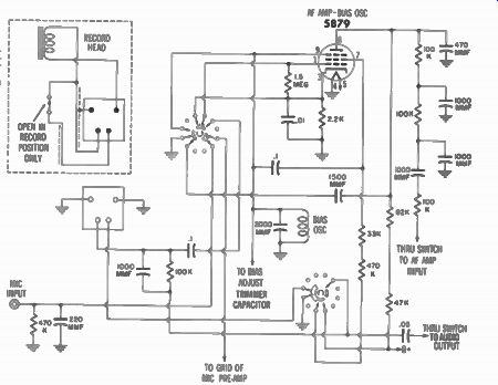
Fig. 8-3. The Input Circuit Used in the Wilcox-Gay Model 3C10 Recorder.
It is interesting to note that the more expensive the tape recorder, the more care has been given to the reduction of noise in the first stage of the playback amplifier. The technique most commonly used is to employ very low noise tubes. The 6SJ7, the 6J7,and the 1620 are all well-known, time-tested friends of the audio engineer. These tubes, all pentodes, possess high gain with low noise. More recently, the 5879, a miniature tube also possessing low noise, has been introduced on the market. This tube is finding wide acceptance in recent years in the design of home tape-recorder amplifiers. A typical circuit using a 5879 tube as a combined A F amp and bias oscillator is shown in Fig. 8-3.
In the field of triodes, the 12AY7, a very low noise tube, has been developed. Several home recorders use the 12AX7 which gives very high gain. See Fig. 8-4. It has a tendency, however, to be somewhat noisy.
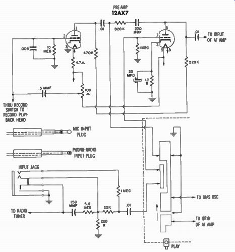
Fig. 8-4. Revere T-700 Input Circuit Using One-Half of a 12AX7 Tube.
Types of Noise The most common type of noise in a tube is hum. Hum is most often introduced from the alternating current used to light the filament of the tubes. In more expensive recorders, as shown in Fig. 8-5, direct current is used to light the filament of the input tube. This, of course, eliminates any possibility of hum being introduced from the tube's heater. However, in less expensive recorders alternating current is used on the filament. In this case it is very important that the filament supply be ground at a neutral point. The cathode also must be adequately bypassed to eliminate hum (see Fig. 8-6). Frequently hum in the input stages is due to the cathode-bypass capacitor losing its capacitance.
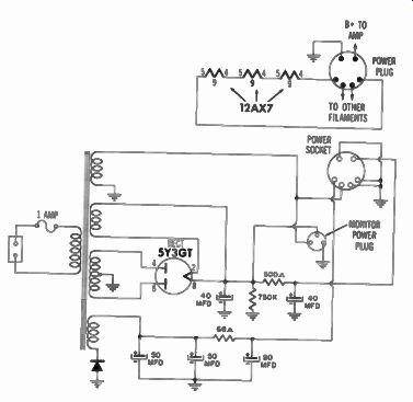
Fig. 8-5. Direct-Current Filament Supply Used in the Concertone Model
1401 Recorder.
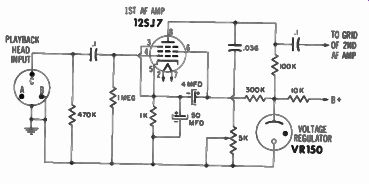
Fig. 8-6. Input Stage Showing Cathode - Bypass Capacitor and Plate Circuit
of the Ampex Model 300 Recorder.
Another common type of noise in a tube is shot noise. This is caused from the electrons leaving the cathodes in groups or clusters rather than in a continuous stream. Then, when they strike the plate, the shot noise sounds similar to the rush of a waterfall. Due to the irregularity of electrons striking the plate, low-noise tubes are especially designed to reduce this effect.
Still another type of noise common in input stages is thermo noise. That is, if a current flows through a resistance a certain type of noise is generated. It is also called white noise since it covers a wide band of frequencies at almost constant amplitude.
In designing input stages, the more expensive recorders use wire wound or carbon deposited resistors rather than the less expensive cast -type resistors to eliminate noise. Often by the simple replacement of the plate resistor and cathode resistor in a home recorder with a wire wound or carbon deposited resistor, a tremendous reduction of noise can be achieved in the input stage. While these resistors do not represent much money as a replacement item for a single recorder, cost makes their use prohibitive in mass production of home-type recorders. This is one trick, easy to perform, that will generally greatly improve the performance of the average home recorder.
Another type of noise common in the input stages of amplifiers is a microphonic condition. This type of noise can be caused by either microphonic tubes or microphonic parts such as a resistor. Microphonic means that a component is sensitive to vibration and will alter its electrical characteristics when vibrated, operating in a manner somewhat similar to a microphone. The worst microphonic offenders are tubes in the input stage. These can be readily detected by tapping the tube. Generally a loud ringing sound will result.
Microphonics are especially bothersome in compact, home-type recorders where the amplifier is mounted next to the motorboard. The motor, of course, creates considerable vibration which is readily picked up by any input tube that is microphonic. Also, since the speaker is mounted in the same case as the amplifier, the vibrations from the speaker will often feed back through the input tube causing an oscillation or howl to build up when the volume control is advanced.
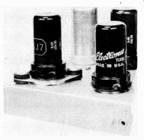
Fig. 8-7. Input Tube Mounted on Rubber Shock Mounts.
To eliminate this condition, low noise tubes are also designed to be non-microphonic as much as possible. However, often it is necessary to specially select tubes for low microphonics. In some cases, such as in the case of 12AX7 tubes, it is necessary to select perhaps one out of ten, or one out of 20 tubes, to get a really low microphonic tube. Practically all recorders mount the input tube on rubber mounts, as shown in Fig. 8-7, which isolate it as much as possible from any vibration. Some manufacturers even hang weights on the tube itself to give it inertia, helping damp out any transmitted vibration. All of these methods help reduce the bothersome microphonic problem.
Harmonic Distortion
While the primary job of both the record and playback amplifier is to amplify or provide gain, it must also give gain while introducing as little noise and distortion as possible.
There are, basically, three types of distortion: harmonic distortion, inter-modulation distortion, and cross-modulation distortion. Many audio engineers staunchly support the dictum that inter -modulation distortion is the only true test of an amplifier's performance. An equal number of engineers take the opposite stand, feeling that harmonic distortion is the only correct criteria of measurement. Actually, all three are mathematically related and should, under most conditions, give similar results even though the method of measurement is different. For purposes of this discussion, when we refer to distortion, we are referring to harmonic distortion.
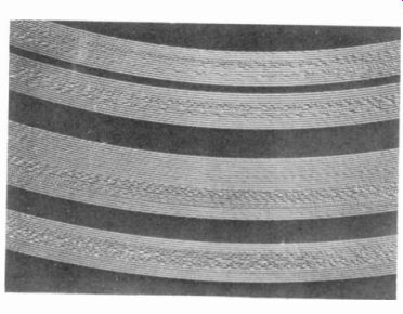
Fig. 8-8. Over-Cut Disc Grooves.
Harmonic distortion refers to the fact that when a frequency signal is recorded during playback, say a pure 400 cycle tone, not only is the 400 cycle tone received but also is reproduced an 800, a 1600, and a 3200 cycle tone, etc. These are the even order harmonics or even multiples of the fundamental frequency. Also reproduced from a 400 cycle tone will be a 1200 cycle tone, a 2000 cycle tone, a 2800 cycle tone, etc. These are the odd order harmonics or odd multiples of the fundamental frequency.
In magnetic recording it is theoretically impossible to get even or second harmonic distortion. If an even harmonic distortion condition exists its cause will originate in the amplifier or be due to magnetized tape. One of the outstanding characteristics of magnetic recording that has made it today's quality recording medium is the fact the process is inherently free of second harmonic distortion.
However, if we should put in a signal stronger than the tape can record, thereby overloading or saturating the tape, the tape reaches a point at which it can no longer be magnetized. Therefore, with additional increases in the signal strength there will be no increase in the tape output, causing an effect known as clipping. Clipping, in turn, results in third harmonic distortion.
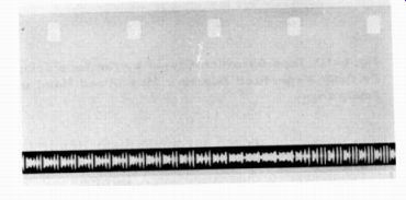
Fig. 8-9. Over-Modulated Optical Sound Track.
The clipping that results from tape overload is not as severe as in other recording methods. For example, in the disc recording process, if the disc is over-recorded, one actually cuts into the adjacent grooves of the recording, resulting in almost total ruin as shown in Fig. 8-8. In photographic recording, by over-recording, the peaks of the waves are chopped flatly off, causing a very harsh type of distortion as shown in Fig. 8-9. However, in magnetic recording, if one over -records there is a tendency to flatten the peaks of the curve in a gradual manner as shown in the graph in Fig. 8-10. This means that although third harmonic distortion is introduced, it is far more gradual compared to other mediums.
Using disc or photographic recording systems, the recording level must be carefully guarded at all times because of disastrous results if the recording were made at too high an amplitude. In contrast, using the magnetic recording medium, even if the amplitude is several times higher than the normal record level, the resulting distortion will often not be too objectionable.
Using a magnetic tape recorder, it is almost impossible for an inexperienced 12 -year old child to make a totally unacceptable recording. Understanding this inherent advantage, it is not difficult to realize why magnetic recording is so popular in the home.
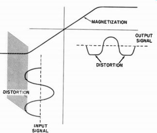
Fig. 8-10. Tape Distortion Caused by the Tape Being Partially Magnetized
Due to a Magnetized Head or Faulty Erase.
We have seen that second harmonic distortion is theoretically non-existent and third harmonic distortion is introduced only by overloading or over-recording the tape. However, if we measure recorders, we will see both second and third harmonic distortion in the output amplifiers. Second harmonic distortion is mainly introduced by faulty design in the amplifier circuits. The output stage of most recorders uses a single pentode tube which often introduces 5 or more percent of total harmonic distortion, a large amount of it being even or second harmonic distortion. The better recorders use large amounts of feedback together with push-pull output stages which tends to reduce this type of distortion, giving better performance.
Second harmonic distortion can be also introduced in the magnetic process if the tape recording condition is at all shifted from its symmetrical counterpoint That is, if the tape is at all magnetized during the recording process, severe second harmonic distortion is possible. (See Fig. 8-11.) The magnetization of the tape can be caused by any one of the magnetic heads becoming magnetized or from the erase system.
The preferred method of checking for magnetized heads is first to demagnetize the heads with a head demagnetizer to determine if the performance has improved. If the diagnosis was correct, there will be a drastic reduction in noise followed by a reduction in distortion.
Still another method is to move, during the recording process, a permanent magnet around the recorder to determine if the amount of noise or distortion is reduced. This will occur if a head is magnetized. The field of the permanent magnet will cancel the residual magnetic field of the head.
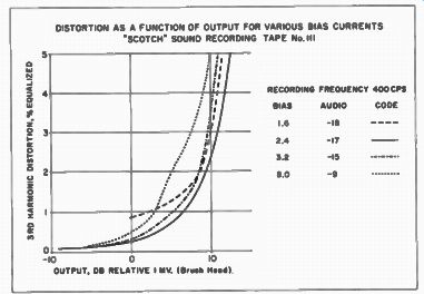
Fig. 8-11. Distortion as a Function of the Signal Level for a Typical
Magnetic Tape.
If the permanent magnet is found to result in lower noise or distortion, the source of magnetization such as a magnetized head should then be chased down and corrected.
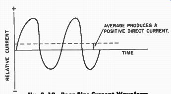
POOR BIAS CURRENT WAVEFORM. AVERAGE PRODUCES A POSITIVE DIRECT CURRENT.
TIME
Fig. 8-12. Poor Bias-Current Waveform.
Another cause of second harmonic distortion results from poor bias waveform as shown in Fig. 8-12. The amplitude of the waves in one direction are stronger than in another direction in the output of the bias oscillator. The bias waveform can often be checked on an oscilloscope to determine if the waveform is symmetrical about its center axis.
The distortion introduced in the amplifier itself is sometimes caused by faulty original design such as a pentode output stage with insufficient feedback. Other possibilities are improper bias on the tubes, caused by a resistor changing value in the cathode circuit of a tube or leaky coupling capacitors resulting in a positive voltage on the grid of the tube, thus changing the bias.
Frequency Response
In addition to amplification gain, low noise, and distortion, an amplifier must also have good frequency response. In the section devoted to equalization, it was explained that the type of equalization chosen primarily determines the over-all frequency response of the recorder. However, the amplifier circuits themselves must be designed to adequately pass the frequencies within the desired range The equalizer circuits, while still a part of the amplifier, are treated separately to facilitate better understanding of their operation.
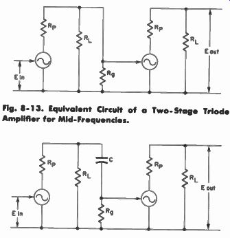
Fig. 8-13. Equivalent Circuit of a Two- Stage Triode Amplifier for Mid-Frequencies.
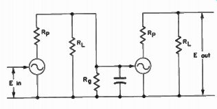
Fig. 8-14. Equivalent Circuit of a Two- Stage Triode Amplifier for Low
Frequencies.
In an equivalent circuit of an amplifier stage followed by another amplifier stage, Fig. 8-13 shows middle frequencies configuration.
At low frequencies, the amplifier circuit appears as shown in Fig 8-14 Note the series capacitor with the grid resistance of the following tube. This capacitor at low frequencies has a high resistance and serves to pass high frequencies and reject low frequencies.
To improve the low frequency response of an amplifier, the size of the coupling capacitors, therefore, should be increased. The larger the capacitor, however, the higher its cost. Because of cost considerations, most manufacturers generally use as small a capacitor as possible, settling for the minimum acceptable low-frequency response. Nevertheless, it should be remembered that there are other factors besides inefficient capacitors that limit the low-frequency response. These factors are covered in detail in the sections devoted to equalization and magnetic heads.

Fig. 8-15. Equivalent Circuit of a Two Stage Triode Amplifier for High
Frequencies.
The high frequency equivalent circuit appears in Fig. 8-15. Note that the equivalent input capacitance of the following stage then serves to limit the high frequencies. In other words, at low frequencies the capacitance is small compared to the grid resistance. This equivalent capacitance has no effect on the circuit. However, at higher frequencies this capacitance tends to short out the incoming signal and limit the high-frequency response. The equivalent capacitance of the following tube cannot be changed except by changing tube and circuit design, which generally does not substantially improve the situation. Therefore, it is necessary to lower the load resistance of the preceding tube. This, in effect, makes the reactance of the shunt equivalent capacitance small in respect to the load resistance of the preceding tubes. While this design will pass higher frequencies, the gain will be adversely affected.
Therefore, the value of load resistance in the tube circuit is a compromise between gain or amplification and high-frequency response. The lower the resistor, the less gain and the better the high-frequency response. Conversely, the higher the resistance, the more the amplification is boosted although the high-frequency response becomes more limited.