The magnetic recording head is the most critical and precision device in the entire recording mechanism. Built to a tolerance as close as a ten-thousandth of an inch, the magnetic head requires an exceptionally high degree of precision in its construction.
Good fidelity in recorder operation, at the present-day speed of 3 3/4 ips, has been achieved. This, in large measure, has been made possible through basic improvements in magnetic heads. Magnetic heads not only determine the low- and high-frequency response of a recorder but also help establish the signal-to-noise ratio.
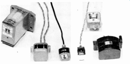
Fig. 9-1. Various Typical Magnetic Heads.
It is imperative to get the strongest signal possible out of the magnetic head since a strong signal means that less amplification is required to reproduce sound at an audible level. As we have seen, noise in magnetic recording mainly originates in the playback amplifier. Consequently, a head that gives a strong signal means that less amplification is needed and less noise will be introduced. The magnetic head is, therefore, the very heart of the magnetic recording process. Fig. 9-1 shows a sampling of some of the magnetic heads in use.
In most discussions it is common to speak of three magnetic heads. First, the erase head, which has the function of obliterating or "wiping" off any signal on the tape, leaving the tape in a completely demagnetized condition. Second, the record head which serves to place a signal in the form of magnetic impulses on the tape. And third, the reproduce or playback head which has the function of converting the stored magnetic impulses on the tape into electrical energy to be amplified for reproduction.
In respect to design, the record and reproduce heads are practically identical. In the majority of machines, especially home-type tape recorders, the same head is used for both record and playback functions. This is accomplished by merely switching the head from the output of the amplifier during the recording process to the input of the amplifier during the playback process. Therefore, we will discuss only the erase head and the record-reproduce head.
The Erase Head
As previously mentioned, the first function of the erase head is to completely obliterate any signal on the tape from the prior recording. The second function is to leave the tape in a completely neutral or demagnetized condition. To completely wipe off any previous signal from the tape is, of course, important since an echo or background of the previous recording would disturb the new recording. The tape must also be left in a completely neutral or demagnetized state in order to eliminate all distortion and noise.
To accomplish both objectives in tape erasure, a magnetic field is needed which is considerably stronger than the strongest signal on the tape. This field must be designed in such a manner that it will highly magnetize the tape in one direction obliterating the previous signal, and then demagnetize the tape, leaving it in a completely neutral state.
Permanent-Magnet Erase
Many early recorders and several present-day machines use what is known as permanent-magnet erase. This is a permanent mag net generally made out of "Alnico" material that is so constructed that one pole completely magnetizes the tape, saturating it to a state far more magnetized than the strongest previous signal. Thus, the permanent- magnet erase serves to obliterate any signal on the tape. Then, either a second magnet, a series of magnets or, still, a diagonal magnetic gap is used to demagnetize the tape and leave it in a neutral state. A typical permanent-magnet erase head is shown in Fig. 9-2.
The chief disadvantage of the permanent-magnet erase is that it must be mechanically operated. This is accomplished during playback by moving the erase head away from the tape by a mechanical linkage so as not to erase the tape. However, the head must be engaged during the recording process. This is somewhat more complicated than the electromagnetic erase head in which only an electrical circuit is opened and closed.
Another disadvantage of the permanent-magnet erase is that it is difficult to obtain a demagnetized tape that is in a completely neutral state Extreme care must be taken in adjusting the magnets so as to remove the saturated field. The Wilcox-Gay uses an ingenious system that involves a diagonal magnetic gap which does a very effective job of neutralizing the magnetic field of the tape.
Fig. 9-2. A Typical Permanent-Magnet Erase Head.
The permanent magnetic erase head, however, has several positive advantages. No strong high-frequency signal source is required, thus eliminating the major demand on the bias supply. (See the section on the bias oscillator.) This greatly simplifies the design of the bias oscillator, meaning that an amplifier can be built with a smaller power transformer. Since there is a smaller tube in t e bias oscillator, many economies result in the amplifier design.
High-Frequency Erase
The high-frequency erase head is a head with a rather wide gap that uses a very high frequency, generally the bias frequency, to erase the tape. The source for the current in this case is described in the section devoted to the bias oscillator. In the high-frequency erase process, as the tape passes over a wide gap (see Fig. 9-3), a series of reversals take place in the magnetic field on the tape. When the tape leaves the gap, it is in an essentially neutral or demagnetized condition.
The high-frequency erase head makes an ideal method of tape erasure. If the signal is strong enough and if the head is correctly designed, the high-frequency erase method will completely obliterate any previous signal, leaving the tape in a completely neutral condition.
It should be pointed out that if this head should become magnetized, which will result from suddenly turning the bias oscillator off, the tape will be left in a magnetized condition, introducing distortion and noise. Therefore, the erase head should be occasionally checked to be sure that it is demagnetized. A head demagnetizer is a useful tool for all magnetic recorders. The demagnetizer should be run slowly across the gap and gradually removed with the current still on as shown in Fig. 9-4. This effectively removes any residual magnetism in the magnetic head.
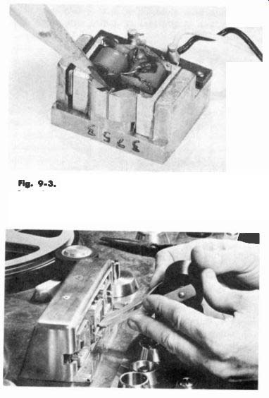
Fig. 9-3. A Typical Erase Head-Note the Long Gap Length Which Allows
a Number of Magnetic Alternations to Take Place on a Given Tope Area During
Erasure.
Fig. 9-4. Using a Head Demagnetizer (Degausser) to Remove Residual Magnetism From a Recorder Head.
Low-Frequency Erase
Still another method of erasing the tape is with a low frequency alternating current source such as that used in the Ampro recorder shown in Fig. 9-5. A 60-cycle field is applied perpendicular to the tape, using a gap that gradually decreases the magnetic field as the tape passes across the erase head. While in theory this method should perform satisfactorily, there is a tendency to leave a low- frequency 60-cycle note recorded on the tape. However, this note is not bothersome since few speakers provided with tape recorders are capable of reproducing this low a frequency. Nevertheless, the signal still remains on the tape, a potential source of trouble if ever a high quality external speaker system is used.
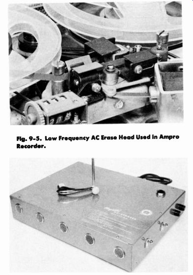
Fig. 9-5. Low Frequency AC Erase Head Used in Ampro Recorder.
Fig. 9-6. A Typical Bulk Eraser.
Bulk Erasure
The final method of tape erasure is accomplished with a bulk tape eraser such as shown in Fig. 9-6.
If a recorder's erase system is working right, it will completely erase any normal signal on present red oxide or dark green high output oxide tapes. However, if a tape is severely over-recorded, or if an old black oxide tape happens to be used, signals can be completely removed by use of a bulk eraser. Certain recorders have no erase system and thus require an external erasure of the tapes. It is for these reasons and the ease that an entire reel of tape may be completely and cleanly erased that a bulk eraser is used.
The tape is placed on a bulk eraser from which a large alternating current field, generally 60 cycles, radiates. The tape is slowly rotated in this field and then is gradually and uniformly withdrawn from the field. It is this gradual withdrawal which makes for a perfect bulk erasing job. It is obvious that if the bulk eraser were turned off while the tape was in its vicinity, there would be a good chance of leaving the tape highly magnetized which is undesirable. Therefore, the tape should be placed on the bulk eraser, the bulk eraser turned on, and e reel very slowly rotated to completely cycle all sections of the ...
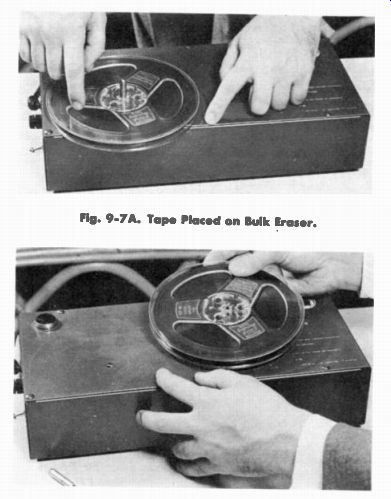
Fig. 9-7A. Tape Placed
on Bulk Eraser.
Fig. 9-7B. Tape Being Removed From Bulk Eraser.
...tape as shown in Fig. 9-7A. Then, as the tape is gradually withdrawn (see Fig. 9-7B), the tape will be first strongly magnetized in one direction and then in the other direction less strongly, then in the original direction still less strongly, eventually wiping off all magnetization.
The two chief errors in bulk tape erasure is that either the tape is rotated and withdrawn from the bulk eraser too quickly, or the bulk eraser is turned off with the tape in its proximity. The tape should be withdrawn at least two feet before turning off the bulk eraser to assure complete erasure of the tape. Since there is no need to erase virgin magnetic tape supplied from the manufacturer, the tape may be directly recorded.
The Record-Reproduce Head
Since the record- reproduce head is generally the same head in most machines, serving a dual function, this discussion will cover the general design of only one head.

Fig. 9-8. The Ring Head is a Closed Magnetic Circuit With a Gap at One
Point. Shown In the Construction of the Brush BK-1090 Head.
In general, the magnetic record- reproduce head is a closed magnetic circuit with a gap at one point. The physical configuration is the reason why it is sometimes called a ring head. (See Fig. 9-8.) On the ring is wound a coil to which the electrical signal is applied during record and during playback the signal is drawn from the same coil.
Frequency Response
During the playback operation, the high frequencies on the tape are generally limited in reproduction by the length of the gap. That is, as the recorded wave lengths on the tape approach the physical size of the head gap, the signal becomes greatly attenuated. In simpler terms, a 7,500 cycle signal wave recorded at 7 1/2 ips will occupy a space of a thousandth of an inch on the magnetic tape. However, from the discussion of the theory of magnetic recording, we saw that for one wave length there are two bar magnets laid on the tape facing each other. Thus, each magnet will be only 5 ten- thousandths of an inch long. Therefore, to properly reproduce a signal of the frequency of 7,500 cycles at 7 1/2 ips, the recording gap must not be any larger than 5 ten-thousandths of an inch or the signal will be greatly reduced.
Because of the present trend toward extending frequency response at lower speeds, it is not uncommon for several home-type recorders, as well as professional machines, to go up to 15,000 cycles at 7 1/2 ips. This means that the gap length must not be longer than 2.5 ten-thousandths of an inch long. It is obvious that extreme precision is required to make a gap of this narrow width.
One might logically reason: Why not make the gap as short as possible to record the highest frequency possible? The disadvantage of a short gap is that the available signal energy is reduced as the gap length is shortened. In other words, as the gap becomes smaller
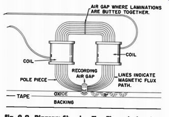
Fig. 9-9. Diagram Showing Flux Through the Ring.
and smaller, more and more of the magnetic flux lines flow across the gap instead of around the entire core length which encircles the coil Of course, the only signal produced is that generated by the flux that passes through the coil. See Fig. 9-9.
Therefore, it is desirable to have a wide gap for maximum signal. However, it is desirable to have a narrow gap for maximum high-frequency response. Generally, the gap length is made as narrow as possible to a point where the desired signal output is still obtained. Present gap lengths generally range between 2.5 to 5 ten-thousandths of an inch long.
The shape of the head at the gap is an important consideration. From the standpoint of wear, the gap should be as deep as possible. Thus, when the tape passes over the head, wearing it down as any sliding friction inevitably will, there should be a good depth of metal before the gap length becomes longer, ruining the high-frequency response. The effects of poor head contact are shown graphically in Fig. 9-10.
It is obvious that when the head has been worn down as shown in Fig. 9-11, the high frequency response will be greatly impaired. Therefore, it is desirable to have a deep gap to prolong head life. A deep gap, however, is undesirable from the standpoint of output. A deep gap has the same effect as a narrow gap in that it prevents all the flux from going through the coil, but rather shorts out the flux through the air gap. Again, a compromise is reached in head design between long wear and high output.
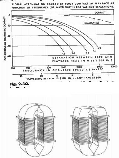
Fig. 9-10. Signal Attenuation Caused By Poor Contact In Playback as a
Function of Frequency for Various Separations Between Tape and Head.
Fig. 9-11. A Badly Worn Head Compared to a New Head. Note Severe Lengthening of the Gap When the Head Wears Beyond the Parallel-Gap Phase.
Magnetic Head Construction
There are generally three methods of magnetic head construction. One is the lamination method (see Fig. 9-12) such as used in the Brush Redhead, the Ampex Therca, and Presto heads, as well as most other professional recorder heads. In the lamination method, thin laminations are stamped to give the desired gap profile and core structure. The laminations are then stacked together to thus form a magnetic head.
If two windings are used on the head, and if the head is made small with symmetrical core structure, the hum field can be nearly balanced out. This is especially important in home-type recorders because close proximity of motors and power transformers produce strong magnetic fields which are picked up by the reproduce head. Thus, if a reproduce head can be correctly designed and adequately shielded so that it will pick up a minimum of hum, a far better signal - to-noise ratio can be obtained in the recording process.
The laminated head design is an excellent construction. Since the laminations are stamped out, any desired gap depth can be made. Thus, a head of very long life can be made by using the lamination method.
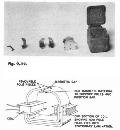
Fig. 9-12. The Lamination Stack Type Head. Shown is the Head Used in
the RCA RT1 IB Magnetic Tape Recorder. REMOVABLE POLE PIECES MAGNETIC
GAP NON-MAGNETIC MATERIAL TO SUPPORT POLES AND POSITION GAP. END SECTION OF
COIL SHOWING HOW POLE PIECE FITS INTO STATIONARY LAMINATION.
Fig. 9-13. Construction of a Head Using a Butted Single Lamination Gap.
The second common type of head construction is found in the Magnecord, the Webcor, the Pentron, and the DuKane recorders. In this type head construction, a single lamination is butted against the end of another lamination to form a gap. (See Fig. 9-13.) The laminations are ground down on the inner surface to provide the necessary gap profile. Then the laminations are in turn inserted between two U-shaped laminations, thus completing the pole structure. This type of construction provides a satisfactory head design.
It suffers, however, from two disadvantages. The magnetic flux path is rather narrow, thus restricting an easy travel through the core structure, resulting in generally lower output. Also, the point at which the gap occurs is rather thin, giving the head a relatively short life. However, one big advantage is that the pole pieces are removable and a new gap can be inserted as shown in Fig. 9-14 without necessitating the purchase of an entire new head and coil assembly. Thus, when the gap is worn and the high-frequency response is impaired, a new but relatively inexpensive pole piece can be inserted. This is generally a factory operation.
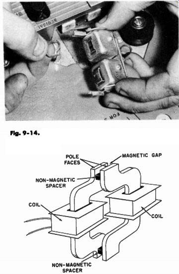
Fig. 9-14. In a Butted Lamination Head the Pole Pieces are Easily Removed
as Shown Here.
Fig. 9-15. Construction of a Head Using Two Laminations and a Spacer to Form the Gap.
Still a third type of head construction is used by Shure Brothers and the Maico Company in their magnatronics head. This type of construction uses a spacer between laminations to form the gap providing a long gap to assure an extended life and a very short gap for good high-frequency response. (See Fig. 9-15.) However, the main disadvantage of this head is the limited amount of tape contact with the head for satisfactory low-frequency response. In order to properly reproduce low frequencies the head surface should be sufficiently long and in close proximity to the tape. The long wave lengths such as those recorded below a hundred cycles at normal recording speeds must be allowed to encircle the gap through the magnetic ring of the head. See Fig. 9-16.
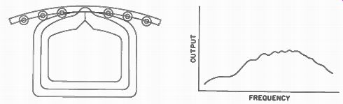
Fig. 9-16. As Long as the Recorded Fields are No Longer Than the Total
Length of the Pole Face on the Reproduce Head, They Will Satisfactorily
Intercept the Gap and Will Encircle the Flux Path. However, If the Recorded
Fields are Longer than the Pole Faces These Low Frequencies Will Be Attenuated
as Shown.
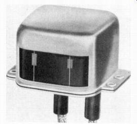
Fig. 9-17. The Shure Brothers TR-5 Erase-Record Head.
Note the Two Lamination Ends and Spacer Which Form the Magnetic Poles and Gap. The Erase Poles are the Wider Poles on the Left and the Record-Play Poles are on the Right.
If , as in the case of the Shure Brothers head, the gap is relatively short, it would, under ordinary circumstances, be difficult for the long wave lengths to encircle it, resulting generally in rather poor low- frequency response. However, the Shure Brothers head (see Fig. 9-17) employs an ingenious method of using a wider lamination on one side than on the other, providing for some increase in low- frequency response. While this increase still does not adequately provide for good low-frequency response, the head possesses excellent wear characteristics and good high-frequency response.
Frequency Response and Output
As we have already seen, in magnetic head construction the pole pieces should be long enough to reproduce low frequencies and the gap should be sufficiently short to reproduce high frequencies. In brief, this is the main criteria for frequency response in the magnetic head.
As mentioned earlier, to obtain a satisfactory output from the tape, the magnetic flux path should be large through the coil area and should be very small at the gap area. Thus, it is desirable that the flux travel through the coil very easily, yet jump over the gap with difficulty. Consequently, the major portion of the flux will pass through the coil rather than the gap. This provides for high output.
One might logically ask: Why cannot a great many turns be wound on a magnetic head to provide high output? Of course, the more turns that are wound on a magnetic head, the greater will be the output voltage. However, when one winds on more than a certain number of turns, the capacity in the winding will become so great as to restrict the high-frequency response.
In many head designs, the resonant point is at the top end of the audio frequency, now occurring near 15,000 cycles. Thus, if any more turns were added to the head, it would be impossible to reproduce the high frequencies since the resonant point would be lowered. Therefore, to obtain good high-frequency response, no more than a certain number of turns can be put on the head. To obtain good output, as many turns as possible are required.
Some heads serve as a low impedance device. Using a head with relatively few turns, the signal can be fed to a transformer which steps it up to a high impedance output. Fig. 9-18 shows a circuit using this method. However, the combined capacitance of the transformer and in the head yields nearly identical results to using a high impedance head. The high-frequency response, then, also limits the output of the head.
Several methods have been proposed to overcome this deficiency. One of the most novel methods still in the development stage is to design a head that feeds a transformer with two different turns ratios. That is, a head would feed a filter network which would separate the low and high frequencies. The low frequencies would be fed to the transformer, having a great turns ratio, providing high output at low frequencies. The high frequencies, however, would be fed to a lower turns ratio which would not suffer from capacitance. From the section on equalization, it can be seen that this technique gives the desired effect since the low frequencies are reproduced at far less amplitude than high frequencies. By properly designing this network, it would be possible to obtain all the equalization in the input stage and obtain high signal level. However, in most recorders, the conventional head feeds a very high gain amplifier with as low a noise as possible after which the equalization is applied.
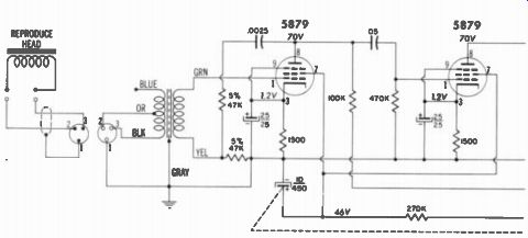
Fig. 9-18. The Mognecord Low-Impedance Input Circuit.
Magnetic Head Wear Magnetic head wear has long been considered a great problem by many people. It is true that in early recorder designs, head wear was a major problem. However, with the introduction of lubricated magnetic tape in 1949, the problem of head wear has been greatly reduced. Modern magnetic tape construction incorporates a lubricant which will generally last the life of the tape.
Many misconceptions surround the problem of head wear. Most people feel that head wear is due solely to the fact that the iron-oxide tape coating is extremely hard while mu-metal is soft. It is true the iron-oxide coating of magnetic tape is almost twice as hard as the mu-metal used in the recording head. The slipping friction of the coated iron oxide particles against the soft mu-metal head may seem at first glance to be abrasive. However, the contact of the hard tape against the soft head is analogous to the action of a bearing.
In bearing construction, the shaft is generally hard and the bearing material itself is soft. This means that the shaft rotating within the bearing runs smooth and free. The lubricating film between the shaft and the bearing provides good protection, assuring an almost indefinite life as long as the lubrication is there. However, it is the dirt that works into the bearing that causes wear, necessitating replacement. The same is true for magnetic tape. It is the dirt that collects on the tape which tends to scour and abrade the head far more than the iron-oxide coating.
The magnetic head, being considerable softer than iron oxide, serves the same function as the soft bearing. The hard iron-oxide tape coating can be compared to a steel shaft turning on the bearing.
Thus, it can be seen that a mu-metal head sliding against magnetic tape provides a reasonably good combination for long head life.
Many materials harder than soft mu-metal have been explored as a possible head replacement. Ferrite core heads have often been ...
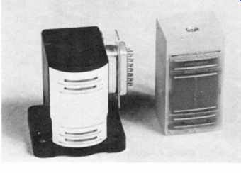
Fig. 9-19. An Experimental
Ferrite Core Multi-Track Head.
... suggested since ferrite is a very hard material, more than twice as hard as mu-metal (see Fig. 9-19). However, in practice, this means that ferrite has almost the same hardness as the iron-oxide coating of the tape. Just as in the case of a steel bearing turning in a steel shaft, the two will scour and abrade. Much the same action occurs the between oxide coating of magnetic tape and the ferrite head. At the present time, the mu-metal head would seem to possess the best all-around wear characteristics. Although ferrite does possess advantages at high frequencies, its wearing properties have so far prevented its widespread use. It is more than likely that in the near future a head material will be developed that is far harder than the iron-oxide coating on tape, solving the head wear problem.
In general practice, however, the average head will wear a thousand hours or more. If the head is of laminated construction, many thousands of additional hours can be expected. The laminated gap construction also provides many thousands of hours of trouble free performance, wearing as well as the laminated construction. However, if the head is of the single lamination construction, generally 500 hours is a reasonably good life expectancy.
Pressure Pads
Intimate head contact is essential in attaining high-frequency response. The professional recorders use a high tape back tension that figuratively stretches the tape across the head, holding it in contact by tension.
However, in home machines, where very little if any back tension is applied, pressure pads are used to hold the tape against the head. The pressure pad is generally a good device to assure intimate tape contact with the head. However, the pressure pad tends to wear the ...
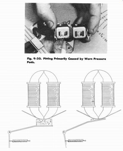
Fig. 9-20. Pitting Primarily
Caused by Worn Pressure Pads.
Fig. 9-21. A New Pressure Pad Compared with a Worn One.
... head somewhat unevenly, developing pits and craters in the head as shown in Fig. 9-20. This will eventually lead to poor tape conformity to the head and loss of high frequencies. Of course, pressure pads themselves are subject to wear and require occasional replacement as shown in Fig. 9-21.
Tape Guides
When tape passes across the head, it is essential that it is accurately guided, enabling it to pass over the head in a straight ...
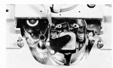
Fig. 9-22. The Tape Guides Employed in Revere Recorder.
... rather than a zigzag manner. The tape must be guided to close tolerances so it will attain the same path on each playback. For example, if the tape is poorly guided, it tends to weave back across the head. The head is then thrown out of alignment with respect to the tape, reducing the high frequencies or causing severe amplitude variations.
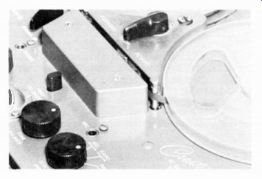
Fig. 9-23. The Pre-Positioning Tope Guides Used in the Crestwood Recorder.
Notice the Tope Fits Into an Accurately Machined Recess In the Guide Post.
A number of guiding systems are employed. Most of them have restricted guides on each edge of the tape placed before the record and reproduce head to guide the tape in a straight path as shown in Figs. 9-22 and 9-23. Several professional recorders employ glass tape guides.
Head Alignment
As we have seen, when the tape is poorly guided it is thrown out of correct azimuth alignment. In correct azimuth alignment, the gap in the head should be exactly perpendicular to the tape, assuring that tapes recorded on one machine will reproduce properly when played on another.
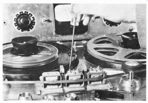
Fig. 9-24. Adjustment of The Ampex 300 Recorder Using a Standard Alignment
Tape.
It is true that when the same head is used for both record and playback, the- azimuth can be out of perpendicular alignment and the tape can still be reproduced satisfactorily since both heads will have the same angle. However, for interchangeability of tapes, it is vital that the azimuth be correctly set.
Excellent azimuth alignment tapes can be obtained from the L. S. Too good Company, the Dubbings Company, and others. These tapes have a high-frequency signal at short wave length recorded on the tape at a very precise 90-degree angle from the edge. The alignment tapes are accurate within several minutes of arc. When adjusting an alignment on a machine, the normal procedure is to play the tape, then adjust the reproduce head for maximum output as shown in Fig. 9-24. Care should be taken to reach the point of maximum output since a lesser peak in output will occur on each side of the maximum output position. The illustration in Fig. 9-25 shows the affect of head misalignment on the output.
When maximum output is obtained, the record head, if a separate record head is used, can be adjusted as shown in Fig. 9-26 by recording a high frequency tone on the tape of approximately one mil wave length where:
Wave length = Tape Speed Frequency
Then the azimuth of the record head can be adjusted until the maximum output from the reproduce head is obtained. Since the reproduce head has been previously set to an accurate azimuth, the record head will also be set accurately.
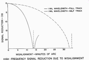
MISALIGNMENT-MINUTES OF ARC HIGH FREQUENCY SIGNAL REDUCTION DUE TO MISALIGNMENT
Fig. 9-25. This Illustration Graphically Shows the Importance of Head Alignment.
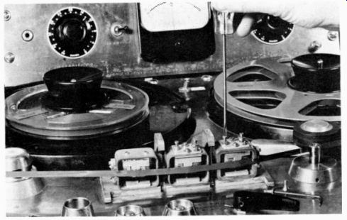
Fig. 9-26. Adjustment of The Record Head of the Ampex Model 300 Recorder.
Full vs. Half-Track Recording
The terms "full" and "half-track" recording are sometimes referred to as single and dual tracks. Dual track means, of course, that two tracks are not recorded but, rather, half of the tape width is used to record a single track instead of the full width of tape. A comparison of the heads used for full and half track recording is given in Fig. 9-27A and B.
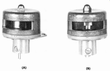
Fig. 9-27. The Presto Full Track Head (A)
Compared with the Half Track Head (B).
Much discussion has been devoted to the merits of full versus half-track recording. Considering the attention and controversy which has surrounded this subject, it is strange that misunderstandings still remain. A persistent folklore abounds which is unsubstantiated by facts.
In theory, a full-track recording should give twice the output voltage of a half-track recording. Or, it should give a 6 db better signal-to-noise ratio, assuming the noise occurs in the amplifier as it generally does.
However, when making a narrower width gap head required for half track, generally a better and more efficient head is obtained. Therefore, in practice, the difference in output between a half and full-track recording is usually only about 3 db. Consequently, one may expect approximately a 3 db better, signal-to-noise ratio using a full-track recording rather than a half track.
The saving in tape economy is, of course, obvious with a half track recording, obtaining twice the recording time on a single reel of tape. Also the half-track head, since its gap width is shorter, is not quite as critical in respect to azimuth adjustment as is the full track head which is still another feature in its favor.
The chief disadvantage of the half-track head recording system lies in the problem of physical tape distortion. If the tape has a long edge or has a wavy surface, use of the half-track head will affect performance more adversely than a full-track head. When the tape is physically distorted, the long edge of the tape will tend to lift away from the head. In recorders using a full-track head, this is often not likely to be serious. In the case of half-track recording, if the tape should lift up on one edge, and if this is the edge upon which the half track recording is being made, severe amplitude fluctuations will result.
Contrary to popular belief, the frequency response is no way affected by the track width. Only the output or signal-to-noise ratio is affected. As was previously explained, in theory a 6 db better output is obtained by using a full-track head as opposed to a half-track head. However, due to the more efficient construction made possible with half-track heads, a full-track head can generally reproduce only 3 db more signal than a half-track head. The frequency response in either case should be identical, assuming identical gap lengths and construction of the heads.
Head Replacement
Each recorder head requires a different amount of bias for maximum performance. Generally, at the time of manufacture of the recorder, the bias is either adjusted or permanently set to fall within a region of proper operation when used with a given head. In professional recorders with adjustable bias, when replacing a head on a machine, the bias should be always readjusted to give optimum performance.
As was noted in the section on bias oscillators, the bias must be adjusted properly for if it is too low, serious distortion will result. If it is too high, the high frequencies will be lost. Therefore, one generally should not put in a head of another manufacturer in a machine designed for a specific type of head since the bias requirements are likely to be different unless, of course, care is taken to properly adjust the bias for the new head.
Heads also vary as to the amount of equalization necessary, especially at high frequencies. Therefore, if changing heads to that of another manufacturer, not only the bias, but also the equalization often will need readjustment. However, on most home-type machines, the head can be replaced with the head of the same manufacturer without difficulty. The only precaution that must be observed is to be sure that the head is properly aligned in respect to azimuth.
Cleaning Heads
It is important to keep magnetic heads free from any deposits of dirt, oxide, or adhesive which may have oozed from poor splices. Generally, a soft cloth or pipe cleaner lightly moistened with carbon tetrachloride as shown in Fig. 9-28 is satisfactory. However, too
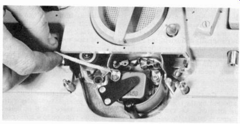
Fig. 9-28. Cleaning a Magnetic Head Using a Pipe Cleaner and Carbon Tetrachloride.
much carbon tetrachloride should be avoided since it tends to corrode the mu-metal head surface and in some cases even dissolves the lamination spacers. Often it is possible to remove any foreign material simply by wiping the head surface with a soft cloth.